1
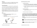
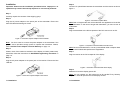
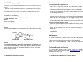
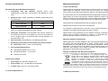
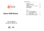
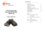
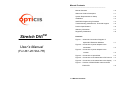
Manual Contents __________________________________________ Stretch DVITM Manual Contents 1-0 Welcome! Product Description 1-1 System Requirements for Setup 1-2 Installation 1-3 Self-EDID Programming Procedure 1-4 Troubleshooting, Maintenance, Technical Support 1-5 Product Specifications 1-6 Warranty Information 1-7 Regulatory Statements 1-8 Pictorials Figure 1 – Schematic Connection Diagram of Optical DVI Extension Modules User’s Manual (For M1-201DA-TR) 1-1 Figure 2 – Connection of power adapter to the transmitter 1-3 Figure 3 – Connection of power adapter to the receiver 1-3 Figure 4 – Connection of optical fiber 1-4 Figure 5 – Connection of the transmitter to DVI source 1-4 Figure 6 – Connection of the transmitter to the display 1-4 Figure 7 – Position of EDID-PRGM. button and Self EDID LED 1- 0 Manual Contents 1-5 Welcome! Congratulations on your purchase of the Stretch DVITM M1-201DA-TR Optical DVI (Digital Visual Interface) Extension Module. This manual contains information that will assist you in installing and operating the product. System Requirements for Setup Hardware requirements You have to have a DVI graphic controller or card having a DVI port in your PC, SUN or Mac systems. It should support the maximum graphic resolution feature of displays to be connected. No special requirements for memory size, CPU speed and chipsets, if you’ve already properly installed your DVI graphic controllers or cards. Product Description The M1-201DA-TR optical DVI module transmits four (4) optical data, Red, Green, Blue and clock and can be extended up to 1500 meters (4920ft) over two LC multi or single-mode fiber at WUXGA (1920x1200) at 60Hz vertical refresh rate. The EDID (Extended Display Identification Data) in a display can be read and restored by just plugging once transmitter to the display. This Software requirements Self-EDID programming feature makes the installation of M1-201DA-TR No special restrictions, if you’ve already properly installed your DVI graphic controller in your OS. more easy and flexile at any variable resolution display systems. For your convenience, UXGA EDID would have been done before shipment as a AC/DC Power Adapter Technical Advisory default. Shipping Group M1-201DA-TR Optical DVI Extension Module: One (1) pair DC power adapter: Two (2) units User’s Manual Option Product: Duplex LC Patch Cord (Single or Multi-mode fiber). The transmitter (Tx) module of M1-201DA-TR is designed for power protection circuit from conflict of power supply between the external DC power adapter and your graphic card through the DVI pin. It offers an option of whether to use an AC/DC power adapter depending on power supply capability of the graphic card through the +5V pin, you are using. However, the receiver (Rx) module should be supplied by an AC/DC power adapter. Note 1: In general, most of laptops or desktop PCs with PCI Express graphic card require using an AC/DC power adapter for the transmitter module. Note 2: If you use laptop or Desktop PC with PCI Express graphic card, we recommend using 5V power adapter for the transmitter. Figure 1 – Schematic Connection Diagram of Optical DVI Extension Modules 1-1 Welcome, Product Description 1-2 System Requirements for Setup Installation Step 5 Important: Please use the installation procedure below. Improper or no operation may result if the start-up sequence is not correctly followed. Connect LC optical fibers between the transmitter and the receiver as shown in figure 4. Step 1 Carefully unpack the contents of the shipping group. Step 2 Plug the 5V power adapter to the power jack of the transmitter. Ensure the blue LED ON after blinking two times. Figure 4 – Connection of optical fibers Note: Both of single-mode and multi-mode fiber are applicable to M1-201DA-TR up to 500meters. In the case of longer than 500meters, you have to use singlemode fibers. Step 6 Plug the transmitter to the DVI receptacle of the DVI source such as PC. Figure 2 – Connection of power adapter to the transmitter Note: You don’t need to connect the power adapter to the transmitter if the graphic source provides enough power to operate the transmitter. Please, refer to AC/DC Power Adapter Technical Advisory on page 1-2. Figure 5 – Connection of the transmitter to the DVI source Note: Be recommended NOT to use any intermediate cable or adapter between them to avoid undesirable performance degradation. Step 3 Please, check if the maximum resolution of the display is UXGA (1600x1200). Otherwise, follow the instructions for Self-EDID Programming Procedure on page 1-5. Step 7 Plug the receiver to the DVI receptacle of the display. Step 4 Plug the 5V power adapter to the power jack of the receiver. Ensure the blue LED ON. Figure 6 – Connection of the transmitter to the display Step 8 Make the PC and the display power ON. Figure 3 – Connection of power adapter to the receiver 1-3 Installation Note: You can replace any DVI cable into an M1-201DA-TR by following the Step1 to 7, while all powers of PC and display are ON. 1-4 Installation Self-EDID Programming Procedure Troubleshooting The graphic source equipment generally requires communication of display information (EDID). Display information (EDID) contains resolution and timing information for your display. The display displays only black screen. M1-201DA-TR supports Self-EDID programming. Self-EDID programming means that the EDID from the display is stored in the transmitter. You should use Self-EDID programming feature if the resolution of the display is not UXGA(1600x1200). Follow these steps to record the EDID of the display into the transmitter unit. Note1 : If you know that EDID is not required by the source, Self-EDID programming is not necessary. Note2 : The default EDID in factory ship-out is programmed in the VESA standard of UXGA (1600x1200) 60Hz. Step 1 - Ensure that all plugs and jacks used by external power supplies (both Opticis and others) are firmly connected. Ensure the blue LED ON. - Ensure that the DVI ports are firmly plugged in to the PC and display. - Ensure that the transmitter and receiver modules plugged correctly to the PC and display, respectively. - Check if the PC and display are powered on and properly booted. - Reset the system by de-plugging and re-plugging the transmitter DVI port or receiver DVI port, or by de-plugging and re-plugging the power cord plugs of transmitter and receiver modules. - Re-boot up the system while connecting the optical DVI extension module. Power on the display. Screen is distorted or displays noises. Step 2 Insert the included 5V DC power adapter into the transmitter. Step 3 Push the EDID PRGM. button of the transmitter with a narrow pin. After fourth time blinking of Self-EDID LED, it will be turned off. - Check if the graphic resolution is properly set. Go to the display properties of Windows and tap the settings. - Ensure that the resolution sets less than WUXGA (1920x1200) at 60Hz refresh ratio. - Reset the system. Disconnect and reconnect the optical DVI cables or 5V power adapters. Maintenance Self-EDID LED EDID-PRGM. button Figure 7 – Position of EDID-PRGM. button and Self-EDID LED Step 4 Connect the transmitter to the display while turned on, not to the PC. The LED on the transmitter will begin to blink rapidly. Blinking indicates reading the EDID. LED will be turned OFF after blinking for about 18~20 sec. The monitor EDID has been recorded. No special maintenance is required for the optical DVI module and power adapters. Ensure that the DVI modules and power adapters are stored or used in a benign environment free from liquid or dirt contamination. There are no user serviceable parts. Refer all service and repair issues to Opticis. Technical Support and Service Disconnect the transmitter from the display. Then, LED ON again. For commercial or general product support, contact your reseller. For technical service, contact Opticis by email [email protected] or visit its website at www.opticis.com 1-5 Self-EDID Programming Procedure 1-6 Troubleshooting, Maintenance, Technical Support Step 5 Warranty Information Product Specifications 1 (One) Year Warranty M1-201DA-TR Optical DVI Extension Modules Compliance with DVI standard: Supports DVI1.0, fully implemented by fiber-optic communication and DDC2B by virtual DDC. Extension limit: 1500m (4920feet) for WUXGA (1920x1200) at 60 Hz refresh rate. Fiber Type Extension Length at WUXGA Multi-mode Fiber 500m Single-mode Fiber 1500m Opticis warrants this optical DVI extension module to be free from defects in workmanship and materials, under normal use and service, for a period of one (1) year from the date of purchase from Opticis or its authorized resellers. If a product does not work as warranted during the applicable warranty period, Opticis shall, at its option and expense, repair the defective product or part, deliver to customer an equivalent product or part to replace the defective item, or refund to customer the purchase price paid for the defective product. All products that are replaced will become the property of Opticis. Replacement products may be new or reconditioned. Graphic transmission bandwidth: Supports up to WUXGA at 60Hz, or 1.65Gbps bandwidth per graphic channel. Any replaced or repaired product or part has a ninety (90) day warranty or the reminder of the initial warranty period, whichever is longer. Fiber-optic connection: The transmitter and receiver modules of M1-201DA-TR have two LC receptacles so as to be connected with one LC duplex single or multi-mode fibers, having 9(8)/125μm or 62.5(50)/125μm core. Opticis shall not be responsible for any software, firmware, information, or memory data of customer contained in, stored on, or integrated with any products returned to Opticis for repair under warranty or not. DDC connection: Virtual DDC by Auto EDID programming. Mechanical specifications of transmitter and receiver modules Operating temperature: 0°C to 70°C Opticis shall have no further obligation under the foregoing limited warranty if the product has been damaged due to abuse, misuse, neglect, accident, unusual physical or electrical stress, unauthorized modifications, tampering, alterations, or service other than by Opticis or its authorized agents, causes other than from ordinary use or failure to properly use the product in the application for which said product is intended. Storage temperature: - 10°C to 85°C Dispose of Old Electrical & Electronic Equipment Humidity: 5% to 85% Warranty Limitation and Exclusion Dimensions: 39mm / 15mm / 69mm (W/H/D) Environmental Specifications AC/DC Power Adapter Power Input: AC 100-240V, 50/60Hz 0.1A Power Output: +5 V, 1A SMPS DC-power Adapter Cord DC Jack: Core is 5 V and outer is GND. 1-7 Product Specifications (Applicable in the European Union and other European countries with separate systems) This symbol on the product or on its packaging indicates that this product shall not be treated as household waste. Instead it shall be handed over to the applicable collection point for the recycling of electrical and electronic equipment. By ensuring this product is disposed of correctly, you will help prevent potential negative consequences for the environment and human health, which could otherwise be caused by inappropriate waste handling of this product. The recycling of materials will help to conserve natural resources. For more detailed information about recycling of this product, please contact your local city office, your household waste disposal service or the shop where you purchased the product. 1-8 Warranty Information UL/IEC Statement This equipment has been tested and found to comply with the limits for medical devices in IEC 60601-1:1994. These limits are designed to provide reasonable protection against harmful interference in a typical medical installation. This equipment generates uses and can radiate radio frequency energy and, if not installed and used in accordance with the instructions, may cause harmful interference to other devices in the vicinity. However, there is no guarantee that interference will not occur in a particular installation. If this equipment does cause harmful interference to other devices, which can be determined by turning the equipment off and on, the user is encouraged to try to correct the interference by one or more of the following measures: y y y y y y y y y Reorient or relocate the receiving device. Increase the separation between the equipment. Connect the equipment into an outlet on a circuit different from that to which the other device(s) are connected. Consult the manufacturer or field service technician for help. Type of protection against electric shock: Class I equipment Degree of protection against electric shock: Not classified - no applied parts Classification according to the degree of protection against ingress of water as detailed in the current edition of IEC 529: IPX0, ordinary equipment This equipment is not suitable for use in the presence of flammable anesthetics or oxygen Mode of operation: continuous operation Certification of Eye Safety This laser product is inside implemented by using 1300/1550nm optical module, manufactured by Opticis Co., Ltd., which are all certified by IEC/EN60825-1 referred in Accession Number 07-1334-0217 as classified in Laser Class1. © 2009 Opticis Co., Ltd. All Rights Reserved Revision 1.1, .Nov. 26, 2009 Opticis Locations Headquarters Opticis Co., Ltd. #304, Byucksan Technopia, 434-6 Sangdaewon-Dong, Chungwon-Ku, Sungnam City, Kyungki-Do, 462-716 South Korea Tel: +82 (31) 737-8033~8 Fax:+82 (31) 737-8079 www.opticis.com North American Office Opticis USA LLC 649 Route 206 Unit 9 Suite 307 Hillsborough, NJ 08844 Tel: 908-837-9652 Fax: 908-837-9078 [email protected] For order support, please contact your Distributor or Reseller. For technical support, check with the Opticis web site www.opticis.com or contact [email protected] 1-9 Regulatory Statements