1
®
2N
BRI Enterprise
User manualVersion 2.0
www.2n.cz
Dear customer,
let us congratulate you on having purchased the 2N® BRI Enterprise system.
This new product has been developed and produced in order to provide the
maximum utility value, quality and reliability to the user. We hope you will be
fully satisfied with the 2N® BRI Enterprise for a long time.
The manufacturer constantly improves the software contained in the
product (the so-called firmware). The technology used therein helps
you download the latest firmware version to the 2N® BRI
Enterprise gateway using a common PC anytime. For the latest
firmware version see www.2n.cz. For necessary instructions refer
to Section 7.2 hereof. We recommend you to apply the latest
version to avoid problems that have already been eliminated.
Grey marked text of this User Guide specifies functions of the
gateway, which will be supported
in newer versions of firmware. You also find
the latest version of the User Manual at www.2n.cz
Check your delivery for completeness according
to the packing list and study this manual carefully before installing
this product. The manufacturer shall not be responsible for damage
caused by any use of this product in contradiction with the User
Manual. The warranty terms and conditions do not apply to damage
incurred as a result of gross handling and/or undue storing of the
product
or violation of the technical parameters included herein.
This manual is very much detailed and includes subsections that are
irrelevant for the basic installation purposes as well as subsections
referring to other BRI GSM gateway models.
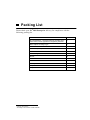
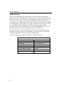
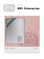
Packing List
Please check your 2N® BRI Enterprise delivery for compliance with the
following packing list.
Item
Pieces
®
*
**
2N BRI Enterprise – check the model type according to the
order number, see the type label on the gateway back side
1
Mains adapter according to type
1
USB cable
1
ISDN 4-wire (RJ-45) cable
2
Antenna
1-2
Wall mounting holder
1
Dowels
2
Screws
2
This manual
1
Warranty certificate
1
Compliance certificate
1
2N product CD
1
none for rack version
according to the number of GSM modules
*
**
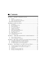
Contents
SECTION 1 – PRODUCT PRESENT ATION ................................................1
1.1. Purpose ...........................................................................................................2
1.2. How to Cut Telephone Costs ........................................................................2
1.3. Other Advantages and Applications .............................................................3
RF Radiation Safety Precautions.............................................................................4
SECTION 2 – INST ALL ATION .........................................................................5
2.1.
2.2.
2.3.
2.4.
2.5.
2.6.
2.7.
2.8.
2.9.
2.10.
2.11.
Get Started......................................................................................................6
Brief Installation Guide .................................................................................7
Proper Mounting ............................................................................................9
PC or LAN Connection ...............................................................................11
Antenna Connection ....................................................................................12
Gateway Power Supply ...............................................................................13
SIM Card Installation/Removal ..................................................................14
NT and TE Connection ...............................................................................14
Status Indicators...........................................................................................16
Lithium Battery Replacement .....................................................................19
Fuse Replacement ........................................................................................20
SECTION 3 – I SDN BRI EXTENSION C ONFIGURATION .............21
3.1.
3.2.
Point-to-Point Connection...........................................................................22
Point-to-Multipoint Connection..................................................................22
SECTION 2 – BRI GSM GATE WAY CONN ECTION OPTIONS .....23
4.1.
4.2.
4.3.
Connection of ISDN TE to 2N® BRI Enterprise .......................................24
2N® BRI Enterprise Point-to-Point Connection ........................................25
2N® BRI Enterprise as Pass-Through Router ............................................27
SECTION 5 – TELE PHONY VIA THE GS M GATE WAY ...................28
5.1.
5.2.
5.3.
5.4.
5.5.
Functions Supported by 2N® BRI Enterprise gateway .............................29
Call Routing Rules ???? Zkusím něco vymyslet :-) .................................29
LCR table .....................................................................................................30
Routing of Outgoing GSM Calls ................................................................30
Routing of Incoming GSM Calls ................................................................32
2N® BRI Enterprise
5.6.
DISA Message Recording...........................................................................33
SECTION 6 ETHERNET PORT CONFIGURATION ............................35
6.1.
6.2.
6.3.
6.4.
Default connection settings .........................................................................36
Installation of Ethernet port drivers............................................................36
Ethernet port configuration .........................................................................38
Default connection settings .........................................................................40
SECTION 6 INTRODUCTION OF CONF IGURATION PROGRAM 41
7.1.
7.2.
7.3.
7.4.
7.5.
2N® BRI config program Installation.........................................................42
Running of BRI config program.................................................................42
Configuration Program Basic Menu ..........................................................45
Button Bar ....................................................................................................54
Topic List and Alphabetical Glossary ........................................................54
SECTION 7 CONFIGUR ATION .....................................................................56
SECTION 9 – CONFIGUR ATION USING TERM INAL .......................81
SECTION 9 – TECHNICAL P AR AM ETERS ...........................................100
2N® BRI Enterprise
1
SECTION 1 –
Product Presentation
Here is a survey of what you will find in this section:
Purpose
How to Cut Telephone Costs
Other Advantages and Applications
RF Radiation Safety Precautions
1
2N® BRI Enterprise
1.1. Purpose
The 2N® BRI Enterprise helps interconnect the ISDN and GSM
networks. It can also be applied in direct ISDN PBX - GSM
connections, in combination with an ISDN telephone set,
analog telephone set or a coin-operated telephone connected
through a terminal adapter, etc.
The voice mode, i.e. an outgoing or incoming call, is the basic
function of the system. The gateway is equipped with all
functions necessary for such use and provides a very high
comfort in this mode.
In addition to voice transmission, 2N ® BRI Enterprise can
send and receive short text messages. This function along with
other additional functions enhances the utility value of the
product.
No extra equipment (an external GSM telephone, etc.) is
needed for normal operation. All programmable parameters are
default-preset in such a manner that you can commence your
telephone traffic the moment you connect the USB and supply
cables, antenna and SIM card and set the ISDN and GSM
parameters.
1.2. How to Cut Telephone Costs
Once your 2N® BRI Enterprise gateway has been connected
to your ISDN PBX, all calls going out to a mobile network are
made directly. This saves your PSTN - mobile network call
costs. All mobile telephone calls of your personnel in the field
are cheaper too.
You are advised to use the most advantageous rate of your
GSM provider for your GSM gateway because all gateway
user call accounts are added up for billing purposes.
You can block groups of numbers in your gateway. You shall
pay nothing for the calls you have barred.
2N® BRI Enterprise keeps detailed records on all calls. This
helps you to find out easily why your bill is higher than it
should be.
2
The Least Cost Router is flexible enough to help you set rules
for GSM calling at the lowest possible operation costs.
The intelligent CallBack function enables your personnel to call
at the cost of your GSM gateway SIM cards.
1.3. Other Advantages and Applications
2N® BRI Enterprise gateways integrates the best of their
respective communication technologies.
The Intelligent Routing of Incoming Calls function (also
including AUTO CLIP Routing function) accelerates
connecting of incoming calls and makes calling more
comfortable.
The DISA function with an easily recordable welcome message
is available.
Unlike mobile telephones, this system does not expose you
to the RF electromagnetic field while making calls.
Password for configuration of the gateway on all ports
CLIP and CLIR for incoming calls from GSM network
ENBLOC / OVERLAP mode of sending called number
to ISDN network
Sending of SMS messages in case of missed call on GSM
network side
Remote GSM control for easy controlling your GSM gateway*
*optional
3
2N® BRI Enterprise
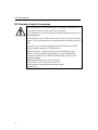
RF Radiation Safety Precautions
It is prohibited to use any transmitters, including GSM gateways, in
areas where explosives are used, such as quarries.
It is forbidden to use mobile phones and thus GSM gateways too at
refuelling points.
A GSM gateway may affect sensitive life-saving devices in medical
centres. So it is prohibited to use mobile phones and GSM gateways
here.
In general, any restriction regarding mobile phones based on RF
energy radiation applies to GSM gateways.
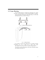
Where necessary, a GSM gateway may be installed at a safe
distance (in the neighbouring building, e.g.) and a BRI ISDN
connection cable may be carried from the GSM gateway to the
original building.
Although GSM gateways are not intended
for aircraft or cars, all relevant restrictions
and regulations regarding mobile phones apply
to them here.
4
2
SECTION 2 –
Installation
Here is a survey of what you will find in this section:
Get Started
Brief Installation Guide
Proper Mounting
PC or LAN Connection
Antenna Connection
5
2N® BRI Enterprise
Gateway Power Supply
SIM Card Installation/Removal
NT and TE Connection
Status Indicators
Lithium Battery Replacement1
Fuse Replacement
1
According to order number
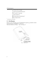
2.1. Get Started
Before you start installing your 2N® BRI Enterprise gateway, get familiar with its
physical structure, arrangement of connectors
and status indicators, see Fig. 1, Fig. 2, and Fig. 12.
Fig. 1 – Bottom View
6
Fig. 2 – Top View
2.2. Brief Installation Guide
Proper mounting – 2N® BRI Enterprise is designed for
suspension on a vertical surface. Fit the holder included in the
delivery on a wall and hang the gateway on it. For details on
the prescribed working position and other recommendations
refer to Subs. 2.3.
Cable connection – connect the gateway using ISDN cable
to your ISDN PBX (or any other ISDN terminals). For more
details on proper wiring refer to Subs. 2.4.
Antenna connection – connect an internal antenna or
an external antenna cable into the SMA antenna connector.
Place the external antenna on a place with a good GSM /
UMTS signal (refer to Subs. 2.5).
Gateway power supply – the delivery includes a mains
adapter. Plug in the adapter connector into the gateway and the
power adapter into a wall socket. The gateway turns
on immediately (see Subs.0).
7
2N® BRI Enterprise
SIM card insertion – SIM cards are inserted in holders
on the gateway top. The SIM card holder is of the push/pull
type, which means that all you have to do is insert a SIM card
and press the holder gently until it snaps into position (see
Subs.2.7). Secure the SIM card with a latch to avoid incidental
removal. !CAUTION! If you use SIM cards with active PIN
protection, first set an identical PIN code for all SIM cards
used in the GSM gateway, save it into the GSM gateway
configuration and only then insert the SIM cards in the GSM
gateway.
PC connection – the gateway parameters are normally set
using the configuration software available on the CD included
in the delivery. To interconnect your PC with the GSM ISDN
gateway use the USB cable included in the delivery*.
Configuration program installation - run the installation file
from the installation CD on a PC connected to the gateway
and install the configuration software (refer to Subs. 7.1).
Configuration program - run the configuration program
installed and select a installed and select a virtual COM port
for your PC - gateway connection. Establish communication
between your PC and the gateway (refer to Subs. 8.1).
2N® BRI Enterprise configuration - now use the
configuration software to set all necessary gateway parameters
- ISDN parameters, basic GSM parameters and tariff
metering/pricing parameters, routing, restrictions, rates, system
parameters, and input and switch properties. Having set the
required parameters, upload the configuration data to the
gateway via a USB. For more details on the configuration
software see Section 8.
*
according to the order number
8
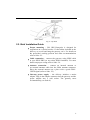
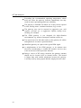
2.3. Proper Mounting
The 2N® BRI Enterprise is designed for mounting on a vertical
surface. For this purpose a wall- mounting holder is available.
Just fit the holder with dowels and screws (Fig. 3) to the wall
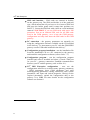
and hang the gateway as shown in Fig. 4.
Fig. 3 – Gateway Holder Wall-Mounting
Fig. 4 – Gateway Hanging
It is possible to operate the GSM gateway in another working
position (e.g. on a desk) for a short time only,
for example in servicing centres for quick testing purposes.
The allowed working temperature and relative humidity ranges
are included in Section 10.
9
2N® BRI Enterprise
Exceeding the recommended operating temperature values
need not affect the gateway function immediately but may
result in more rapid ageing and lower reliability.
The gateway is intended for indoor use. It may not be exposed
to rain, flowing water, condensed moisture, fog, or mist.
The gateway may not be exposed to aggressive gas, acid
vapours, solvents, etc. or aggressive liquids, during cover
cleaning, for example.
The GSM gateway is not designed for high-vibration
environments, e.g. means of transport, machine rooms, etc.
Free space has to be left under and over the gateway for cables
and agitated air to remove operational heat.
Install the gateway on a place with a good GSM signal.
A misplacement of the GSM gateway or its antenna near
television, broadcasting or similar RF-sensitive devices may
evoke an adverse effect upon their function.
Being a source of RF energy emission, the gateway antenna
should not be located close to human bodies. The hazard
is higher than with mobile telephones because the gateway
is usually used by many people and thus employed more often.
10
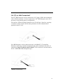
2.4. PC or LAN Connection1
The 2N® BRI Enterprise can be connected to a PC using a USB cable terminated
with a USB-B connector. A direct connection of 2N® BRI Enterprise and a PC is
necessary for the initial gateway configuration.
The gateway USB port default parameters are 921,600 bps, 8 data bits, no parity,
1 stop bit, no flow control. Set the same parameters for the communication
program on the PC side.
2N® BRI Enterprise can be connected to the 10/100BASE-T (Twisted Pair
Ethernet) LAN using a standard straight through cable terminated with a RJ-45
connector (Chyba! Nenalezen zdroj odkazů.). This connector is not included in
all 2N - ISDN BRI GSM Enterprise types.
1
depends on order number
11
2N® BRI Enterprise
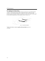
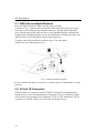
2.5. Antenna Connection
The BRI GSM gateway has one SMA antenna connector for each GSM module,
see Fig. 5. An external antenna cable is connected to these connectors. The
external antenna should be installed vertically on a place with a good GSM signal.
For the technical parameters of the antennas refer to Section 10.
Fig. 5 – Antenna Connection
Tighten the antenna connector gently with your hand, never use
a wrench!
12
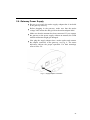
2.6. Gateway Power Supply
Be sure to use only the mains supply adapter that is included
in the gateway delivery.
Before plugging in the gateway, make sure that the mains
voltage value meets the data given on the mains adapter label.
Make sure that the antenna has been connected. If you connect
the gateway to the power supply without an antenna, the GSM
module transmitter might get damaged.
Now plug the supply adapter into a mains socket and connect
the adapter connector to the gateway, see Fig. 6. The status
indicators indicate the proper operation. For their meanings
refer to Subs. 2.9.
Fig. 6 – Supply Adapter Connection
13
2N® BRI Enterprise
2.7. SIM Card Installation/Removal
Insert the SIM card into the SIM card slots with your hand
as shown in Fig. 7. Please make sure that the SIM card contact plates are on the
side closer to the GSM gateway antenna connectors. Having inserted the SIM
card, push the card gently until you hear a click signalling that the card has been
snapped by the push/pull holders. Secure the SIM card by shifting the latch to the
right in order to avoid incidental removal of the SIM card.
To remove the SIM card take the opposite steps. You can replace
a SIM card even with the gateway on.
Fig. 7 – SIM Card Inserting Procedure
In case of SIM card replace is necessary to make restart of GSM module or whole
gateway.
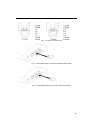
2.8. NT and TE Connection
ISDN terminals are connected to the NT and TE connectors depending on the
configuration of your telecommunication equipment. They are connected using a
4-wire passive bus through RJ-45 connectors. For NT or TE connections see Fig.
9 and Fig. 10. The RJ-45 pins for TE and NT are shown in Fig. 8.
14
Fig. 8 - TE and NT Connector Pins
Fig. 9 - ISDN GSM Gateway Connected as Network Terminal (NT)
Fig. 10 - ISDN GSM Gateway Connected as ISDN Terminal (TE)
15
2N® BRI Enterprise
ISDN equipmnet (TE)
Fig. 11 - Basic ISDN GSM Gateway Wiring Diagram
Choose the specific wiring as shown in Section 4.
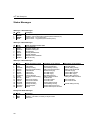
2.9. Status Indicators
There is a panel with five LEDs on the gateway upper cover for a quick GSM
gateway status detection (see Fig. 12). The Power LED signals that the gateway as
a whole is in operation. The BRI 1 and BRI 2 LEDs indicate the status of both the
B channels of the basic ISDN extension, and the GSM 1 and GSM 2 LEDs
indicate the status of the respective GSM modules.
CH1
CH2
Fig. 12 - Signalling LEDs
Basic diagnostic tests and gateway initialisation are performed automatically
whenever the gateway is connected to supply voltage. Each test step is signalled
by a specific colour combination of the LEDs. If a test step fails, the indicator
combination related to the failed test remains lighted.
This provides a convenient troubleshooting tool to the technical support
personnel.
16
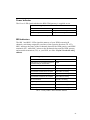
Power Indicator
The Power LED signals whether the BRI GSM gateway is supplied or not.
Power Indicator (green)
Power
LED colour/status
No light
The system is not working. / Blown fuse.
Continuous light
The system is working.
Tab. 1 – Survey of Power Indicator Statuses
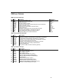
BRI Indicators
The BRI 1 and BRI 2 LEDs signal the statuses of your ISDN extension B
channels, each being assigned to two lines of the opposite direction (TE /NT).
BRI 1 indicates the status of the B channels between the GSM gateway and ISDN
terminals (NT), while BRI 2 relates to the B channels between the GSM gateway
and network termination (TE), or your PBX, see Subs. Chyba! Nenalezen zdroj
odkazů.
BRI 1 / BRI 2 (green)
BRI 1 / BRI 2
LED colour / status
Channels are not occupied and physical
and data link layers are activated
no light
TEI binded, link layer not activated
Orange / BRI 1 or BRI 2 are shining
1 B-channel towards TE is occupied
Green / BRI 1 is shining
2 B-channels towards TE are occupied
Green / BRI 1 is shining
1 B-channel towards NT is occupied
Green / BRI 2 is shining
2 B-channels towards NT are occupied
Green / BRI 2 is shining
TE not connected
Red / BRI 1 is shining
Physical layer activated
Red / BRI 1 or BRI 2 are blinking
NT (PBX) not connected
Red / BRI 2 is shining
Physical layer activated
Red / BRI 2 are blinking
Tab. 2 – Survey of BRI 1 / BRI 2 Indicator Statuses
17
2N® BRI Enterprise
GSM Indicators
The CH1 and CH2 indicators signal statuses of the respective GSM modules.
Whenever the 2N® BRI Enterprise is started, detection of the GSM modules and
SIM cards is carried out. This process is signalled by a red LED, which goes on a
few seconds after voltage is supplied. The GSM module detection takes a few
seconds. In case a GSM module or SIM card is absent, the red LED keeps shining.
If a GSM module is not supplied, the respective GSM LED is blinking red. After
a correct GSM module initialisation, the SIM card starts logging into the
provider's network, which is indicated by a quickly blinking green colour. If the
log-in has been successful, the LED goes out. If not, it shines red.
In normal operation, a slowly blinking green LED indicates establishing of an
incoming or outgoing call and a permanently green LED means a successfully
established connection within the respective GSM module.
A survey of GSM module status signalling is included in Tab. 3
GSM indicators
GSM 1 or GSM 2
LED colour / status
The module is ready and logged-in
No light
Call establishing
Green / blinking slowly 1:1
Currently made call
Green / shining
SIM card initialisation
Green / blinking quickly 1:1
SIM card initialisation in progress
Shining red
GSM module / SIM card absent
Red / shining
GSM module not supplied
Red / blinking quickly
Tab. 3 - Survey of GSM Module Status Signalling
18
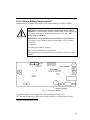
2.10. Lithium Battery Replacement2
Lithium battery contains only models with serial number 09-XXXX-XXXX!
WARNING! An incorrect battery replacement may result in
explosion. For replacement, batteries of the same or equivalent type
as recommended by the manufacturer may be used only. The
battery type is CR2032.
WARNING! Never use metal tools for battery replacement to
avoid short-circuit. Battery short-circuiting may result in battery
destruction
or explosion.
Keep the proper battery polarity.
Dispose of used batteries in accordance
with applicable waste regulations, for example in waste recycling
centres.
Fig. 13 – Motherboard Diagram
The lithium battery only supplies the real time internal clock in the
2N® Enterprise gateway in the event of power failure. It is unnecessary for the
2
depends on gateway order number.
19
2N® BRI Enterprise
gateway functionYou are recommended to replace it after three years for
preventive purposes or, at least, check the voltage with a voltmeter (the value
should not drop below 2.9 V).
A completely low battery results in the 2N® BRI Enterprise gateway losing the
time and date information - false data appear also in the service log buffer listing.
Replacing the lithium battery, first disconnect your 2N® BRI Enterprise gateway
from the mains and open the cover. Remove the old battery from the holder using
a suitable tool
and install a new one.
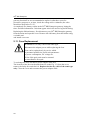
2.11. Fuse Replacement
WARNING! Use only a fuse of the same type.
Disconnect the adapter power while replacing the fuse.
Fuse can be replaced only by service which
is personnel qualified to check such parameters
as power consumption, DC voltage etc.
If fuse fails again, unit must be returned
to manufacturer for repair
To exchange the fuse disconnect power adapter cable first.
The location of the fuse on the main board is on the Fig. 13. Open the cover,
remove the faulty fuse and check it. Replace the fuse by a fuse of the same type
only. Close the cover and reconnect the power adapter cable.
20
3
SECTION 3 –
ISDN BRI Extension Configuration
To configure your 2N® BRI Enterprise properly, you have to know the type of
connection of your ISDN terminals. This section helps you install your GSM
gateway between already interconnected ISDN terminals.
For information on the ISDN type refer to your ISDN provider's registration form
or check with your telephone network administrator.
This section includes:
Point-to-Point Connection
Point-to-Multipoint Connection
21
2N® BRI Enterprise
3.1. Point-to-Point Connection
The Point-to-Point (EuroISDN with DDI) configuration interconnects directly one
ISDN terminal (TE) with a network terminal (NT) (see Fig. 14). This type is
applied mainly where PBXs are connected to the ISDN.
Fig. 14 - Point-to-Point Connection
3.2. Point-to-Multipoint Connection
Point-to-Multipoint (EuroISDN with MSN) is another type
of ISDN terminal interconnection. Here the network terminal (NT) is
interconnected with up to eight ISDN terminals through a 4-wire passive bus as
shown in Fig. 15.
Fig. 15 - Point-to-Multipoint Connection
22
4
SECTION 4 –
BRI GSM Gateway Connection Options
This section deals with the connection options of the 2N® BRI Enterprise to the
ISDN Basic Rate extension.
This section includes:
Connection of ISDN TE to
23
2N® BRI Enterprise
2N® BRI Enterprise Point-to-Point Connection
Chyba! Nenalezen zdroj odkazů.
2N® BRI Enterprise as Pass-Through Router
24
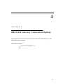
4.1. Connection of ISDN TE to 2N® BRI Enterprise
The connection in Fig. 16 provides communication via a GSM gateway without
PSTN connection. The ISDN telephone set
is connected to the NT port of the GSM gateway, while a mains adapter
simulating power supply from the public network
is connected to the TE port. The adapter is available under the part No. 5020001.
ISDN phone
ISDN power adapter
Fig. 16 - ISDN Telephone-Gateway Connection with Power Supply Simulation
25
2N® BRI Enterprise
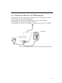
4.2. 2N® BRI Enterprise Point-to-Point Connection
This type of connection is especially suitable for direct calls
from an ISDN branch network to a GSM network.
Fig. 17 - ISDN BRI GSM Point-to-Point Connection as ISDN NT
26
Fig. 18 - ISDN BRI GSM Point-to-Point Connection as ISDN NT with Public ISDN
Synchronisation
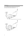
Fig. 19 - Multiple ISDN BRI GSM Gateway Connection
27
2N® BRI Enterprise
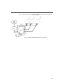
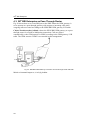
4.3. 2N® BRI Enterprise as Pass-Through Router
Fig. 20 shows how to save one BRI port to the PBX where the GSM gateway is
set to operate as a pass-through gateway with respect to incoming calls while
outgoing calls are routed according to the ISDN BRI GSM gateway LCR table.
Chyba! Nenalezen zdroj odkazů. shows the ISDN BRI GSM gateway as a passthrough router for a Point-to-Multipoint connection. Calls are routed
automatically to the GSM network or ISDN according to the GSM gateway LCR
table. The GSM gateway DTMF is not needed in this arrangement.
Fig. 20 - BRI ISDN GSM Gateway Connection as Pass-Through Router with PBX
Mrkni na komentář napravo, už tu byl předtím.
28
5
SECTION 5 –
Telephony via the GSM Gateway
This section contains information on routing calls through the GSM gateway.
Gateway configurations are described that help you make the most of the gateway
potential and minimise your telephone costs.
This section includes:
29
2N® BRI Enterprise
Functions Supported by
Call Routing Rules
LCR table
Routing of Outgoing GSM Calls
Routing of Incoming GSM Calls
DISA Message Recording
30
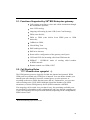
5.1. Functions Supported by 2N® BRI Enterprise gateway
Call routing according to time and called destination through
the destination's operator;
Auto CLIP routing;
Outgoing call routing by time LCR (Least Cost Routing);
DISA (tone dial-in);
DISA to GSM (tone dial-in from ISDN ports to GSM
networks);
CallBack to GSM;
Virtual Ring Tone
SMS sending/receiving;
SMS at no Answer;
Password for configuration of the gateway on all ports
CLIP and CLIR for incoming calls from GSM network
ENBLOC / OVERLAP mode of sending called number
to ISDN network
Remote control over GSM (CSD) 3
5.2. Call Routing Rules
???? Zkusím něco vymyslet :-)
The GSM gateway ports are logically divided into internal and external. While
GSM ports are external only, ISDN port is internal. You can define whether your
internal port calls should be routed to external ports, or to the operator, or
according to the active DISA function (tone dial-in). Furthermore, you can route
calls according to the CLIP, MSN (Multiple Subscriber Number) (for ISDN
extensions), or direct GSM gateway dial-in (ISDN extension with DDI).
If an outgoing call is routed via a port that is busy, the remaining available ports
are searched for (depending on the configuration) and if no allowed outgoing port
is free, the outgoing call is rejected with defined (depending on the configuration)
ISDN release cause.
3
Must be activated by proper licence code
31
2N® BRI Enterprise
The routing algorithm routes outgoing calls according to the outgoing call type,
current time rate, day in a week, and GSM provider's free minutes if any
(depending on the configuration).
5.3. LCR table
The LCR (Least Cost Routing) chart is the key telephone cost cutting factor. It
helps you set the call routing rules according to the CLIP, daytime and day in a
week. By entering public holidays into the LCR table you achieve even more
remarkable cuts.
To make call routing to external ports based on prefixes and the LCR table work
properly, enter the GSM provider prefix and the count of prefix-following digits
into the GSM destination table.
The ISDN GSM gateway also allows you to route outgoing GSM calls on the
basis of the SIM card position. In this case, outgoing calls are not routed
according to the GSM provider's number but through the defined GSM module.
In addition, the ISDN ports can work in the pass-through mode. This means that
all calls are routed to the respective complementary port without any check.
Namely, from TE to NT and vice versa.
.
5.4. Routing of Outgoing GSM Calls
If the GSM gateway is connected to your PBX internal line, enable the DISA
function to the GSM network to make your GSM gateway answer every call
routed to it by the PBX and wait for further dialling to GSM networks.
Routing of outgoing calls via the GSM gateway proceeds as follows:
The calling subscriber dials a number.
The GSM gateway waits for further digits to be dialled. This
timeout results in a certain delay between the subscriber's
dialling and the subsequent dialling by the GSM gateway.
Therefore, select the Default count of digits for called
destinations while configuring your GSM gateway. Then the
GSM gateway initiates the outgoing call processing algorithm
on receiving the last digit.
The dialling prefix is first checked with the prefixes included
on the first line of the LCR table + prefix list. If no match is
found, the following line is used for comparison.
32
If the prefix matches a LCR prefix, the call time is checked for
match with the routing rule on the line. Again, if no match
is found, the following LCR table line is searched.
In case the prefix and call time comply with the routing rules,
the call is routed according to the first routing rule included
in Groups and GSM outgoing callss to the module
corresponding to the particular GSM outgoing calls.
If the selected GSM module is busy or has an insufficient
credit, the preceding step is repeated for the following line
of the LCR table section. If there is no record, the next LCR
table line is searched.
In case the selected GSM module is free and has a sufficiently
high credit, the GSM gateway starts dialling a GSM number.
If the calling subscriber number has an unknown prefix, or all
routes are busy, the GSM gateway rejects the call request.
An outgoing call is not billed until the called party answers the
call.
The GSM network signals the off-hook and the GSM gateway
transfers this information to the PBX.
33
2N® BRI Enterprise
5.5. Routing of Incoming GSM Calls
Incoming calls from the GSM network are subject to the algorithm described in
Chyba! Nenalezen zdroj odkazů. and the following steps:
Incoming calls are processed according to the Mode parameter
in the GSM incoming calls chart. The following options are available:
Reject incoming calls – all incoming calls are rejected.
Ignore incoming calls – incoming calls are not routed
to extensions. The call request is either rejected or ignored
(the calling party hears the ringing tone) on the GSM network
side.
Report to PC – the information on an incoming call is sent to a
PC equipped with the management software. The calling
subscriber gets a voice message or check ringing tone.
The management software then completes the call routing
procedure.4
CallBack – this function helps establish connection on the
account of the SIM card inserted in the GSM gateway.
The incoming call is either ignored or rejected. After the
calling subscriber hangs up, the GSM gateway establishes
connection to the defined extension. When the extension
answers, the GSM gateway replays the CallBack message
to the extension while establishing a connection to the
previously calling subscriber in the GSM network. After the
CallBack message, the GSM gateway interconnects the call.
If neither of the above-mentioned options is selected, the
AutoCLIP routing table is checked. If the calling number
is found, the call is routed to the extension whose number
is assigned to the calling number in the table.
4
not available yet.
34
In case the calling number is not included in the AutoCLIP
routing chart, or the AutoCLIP routing function is disabled,
the gateway receives the incoming call and either replays
a voice message or transmits the dial tone to the calling party.
Then the gateway awaits the count of digits necessary for call
establishing. To define the minimum and maximum counts
of DTMF digits use the GSM incoming groups menu.
If the gateway does not receive the minimum required count
of digits and no other digit comes from the GSM network
within the timeout defined in DTMF dialling delay, the call
is rerouted to the operator as the case is when the extension
number dialled by the calling party is unknown.
If the call rerouting to the operator is inactive, the incoming
call is rejected.
5.6. DISA Message Recording
If the DISA function is enabled and a welcome message recorded, this voice
message is replayed to every incoming call whose number is not included in the
AutoCLIP routing table. After the message is replayed, the gateway waits for the
first DTMF digit for a timeout defined in the GSM incoming calls – Timeout while
inputing DTMF digits [s]: table. Having received the count of digits defined in
GSM incoming calls – Minimum digits in DTMF, the gateway activates the PBX
or telephone connection with the number received by the DTMF via the ISDN
port. For more details on the gateway configuration refer to Section 8.
To establish connection with a lower count of digits than defined in GSM
incoming calls – Maximum digits in DTMF, terminate the dialling with the '#'
character. When the DISA does not receive the pre-programmed count of digits or
the '#' character, the connection is not established. Therefore, enable the operator
service while activating the DISA function (in the router mode only, no '#' is
needed in the PBX mode).
There are three ways to program the DISA voice message into the gateway:
Record DISA using configuration program
Record the voice message from GSM telephone
Record DISA into your PC and save the wav file into your
gateway using the XMODEM protocol and defined AT
commands .
35
2N® BRI Enterprise
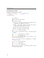
DISA Message Recording using terminal and GSM phone
Recording of DISA message
Open terminal window (see Subs 5).
Establish connection with your GSM phone using AT
command: at!sg0=phone_number_of_your_GSM_phone
Accept incoming call from your GSM gateway by GSM phone.
(CLIP of SIM card plugged in SIM card holder 1)
Enter AT command at!m=record in terminal window which
results in recording of DISA message (60 s max)
To stop recording of DISA message press ENTER
Finish the phone call by hanging up or entering of AT
command at!d
Erasing of DISA Message
To get an information on recorded DISA Message enter AT command
at!m=status. To erase DISA message enter AT command at!m=erase in terminal
window.
Recording of DISA Message using terminal and PC
Recording the voice message into your PC keep the maximum length of 65 s,
compression according to the ISDN A-law codec, mono, sampling frequency of
8 kHz. The voice message recording program is part of your GSM gateway
software delivery. Summary of parameters the file must meet is in table Tab. 4
below. Name the file Disa.wav and upload it to 2N® BRI Enterprise using a
terminal and the XMODEM transmission protocol.
DISA Voice File Parameters
Sound format
Sampling frequency
Count of channels
Codec
Wav
8 kHz
1 mono
ISDN A-law
Tab. 4 DISA Message File Parameters
36
6
SECTION 2
Ethernet port configuration *
This chapter focuses on installation and configuration of Ethernet port for
communication over 10/100BaseT computer network. This port is optional part of
the gateway. It is possible to skip this chapter if your gateway is not equipped
with this port.
This section includes:
Default connection settings
Installation of Ethernet port drivers
Ethernet port configuration
Default connection settings
*
This chapter is intended for BRI Enterprise Gateway with 10-BASE-T port (Twisted Pair Ethernet)
37
2N® BRI Enterprise
6.1. Default connection settings
Default gateway IP parameters:
IP address:
10.1.10.100
Port:
1001
Warning: There is no password protection! Before installation, please activate it
by configuration tool (section 3.3.3, page 47).
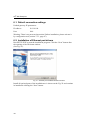
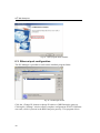
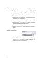
6.2. Installation of Ethernet port drivers
Run SETUP.EXE to start the installation program. Click the “Next” button after
the opening of the Welcome window.
(See Fig. 21).
Fig. 21 – Ethernet port installation Welcome window
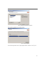
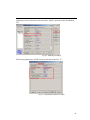
Install all optional parts of the installation as is shown on the Fig. 22 and continue
in installation clicking the “Next” button.
38
Fig. 22 – Selection of optional part of installation
Wait until the installation successfully finishes.
Fig. 23 – End of installation
In the following window check „Open program folder“ checkbox. (See Fig. 24).
39
2N® BRI Enterprise
Fig. 24 – Open program folder checkbox
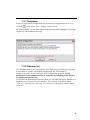
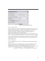
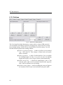
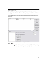
6.3. Ethernet port configuration
The DS Manager is possible to run from the installed program folder.
Fig. 25 - DS Manager window
Click the „Change IP“ button to change IP address of BRI Enterprise gateway.
Clicking the “Settings” window allows complete configuration of RS232-Ethernet
converter, which is present in the BRI Enterprise gateway. This program allows
40
uploading of new firmware to the converter, which is present on the installation
CD.
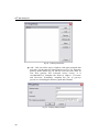
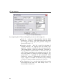
Fig. 26 – Ethernet port settings
Please keep parameters of RS232 port as shown on the Fig. 27.
Fig. 27 – Configuration of RS232 converter
41
2N® BRI Enterprise
6.4. Default connection settings
The gateway supports standart telnet protocol. For connection you can use any
terminal which supports Telnet protocol or configuration tool. Gateway supports
only one sesstion in one time!
42
7
SECTION 6
Introduction of Configuration Program
This section introduces the 2N® BRI Enterprise configuration software, which is
part of the installation CD supplied together with the gateway.
Here is what you will find in this section:
2N® BRI config program Installation
Running of BRI config program
43
2N® BRI Enterprise
When the installation has been completed, run the program by clicking on BRI
config program in your PC software menu, or clicking on the desktop icon, or
opening the BRI config program.exe file that you will find in the respective
location installed by you using any explorer or file browser.
Note: BRI config program is designed for 2N® BRI Enterprise and BRI lite GSM
gateway type. Type of connected gateway is detected automatically –
configurations windows are changed accordirg gateway type or by selecting right
template.
Templates
Configuration Program Basic Menu
Button Bar
Topic List and Alphabetical Glossary
7.1. 2N® BRI config program Installation
By inserting the installation CD in the CD-ROM drive you initiate installation
automatically. If you have not enabled the CD autorun function, initiate
installation by opening the setup.exe file of the BRI Enterprise software. Follow
the installer instructions and wait until the installation has been completed. The
guides and autoupdate program are installed together with the 2N® BRI Enterprise
software.
7.2. Running of BRI config program
When the installation has been completed, run the program by clicking on BRI
config program in your PC software menu, or clicking on the desktop icon, or
opening the BRI config program.exe file that you will find in the respective
location installed by you using any explorer or file browser.
Note: BRI config program is designed for 2N® BRI Enterprise and BRI lite GSM
gateway type. Type of connected gateway is detected automatically –
configurations windows are changed accordirg gateway type or by selecting right
template.
44
7.2.1. Templates
In case of not defined configuration file (first start of congiguration tool), or by
use icon
,or by menu “File> Default configurations.
By using template you can load default configuration (basic settings) for your type
of gateway and installation site type.
7.2.2. Gateway list
For administration of only one gateway is the following procedure not necessary.
It is possible to operate with default configuration file, which name is
unnamed.cfg and is saved in directory with configuration program. Saving
parameters to the configuration file is automatic by switching items in topic
or alphabetical glossary tag.
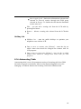
To facilitate the administration of more than one 2N® BRI Enterprise gateway it is
possible to use Gateway selection window. This window is located in menu
“Gateway – Gateway list” (see sub. 1.3). Selection of this opens window shown
at Fig. 28.
45
2N® BRI Enterprise
Fig. 28 – Gateway list Window
Add - click on Add to open a window with some essential data
necessary for the gateway identification (see Fig. 29). Enter the
gateway name chosen by you into the Gateway name item. In
case that gateway has activated secure access, it is
recommended to complete the Gateway address, Username
and Password. Eventually, complete the File of gateway
parameters including the directory path and filename.
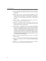
Fig. 29 – Gateway Editing Window
46
Edit – used for editing identification data on the gateway
entered. To edit the data, select the required gateway from the
list of used gateways and click on Edit.
Remove – used for removing a gateway from the list of
gateways.
Remove all – used for removing ALL gateways from the list.
Select! – click on this button to select a GSM gateway and
whose parameters can be set after Close is pressed.
Default – by clicking on this button you start working with the
default parameters.
Connect – used for closing the Gateway selection window and
opening the gateway configuration window.
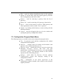
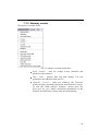
7.3. Configuration Program Basic Menu
The following items are available in the main configuration program menu:
File – for physical work with the configuration file, default
configuration and templates.
Gateway – contains items for connect and disconnect with
gateway. Also contains item Gateway list.
Gateway control – contains the Gateway operation monitoring
functions, Firmware, Licence, and Date and time
specifications, and functions for Gateway reset and uploading
of Factory settings. All functions located in this sections
requests on-line connected gateway!
Settings – menu items for Gateway selection, gateway
Communication settings and Language setting of the
configuration software.
Help – information on the About application of the
configuration software together with contacts to the technical
support personnel.
47
2N® BRI Enterprise
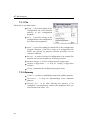
7.3.1. File
This menu is accessible under.
Load – is used for loading of the
configuration file of the selected
gateway to the configuration
program.
Save – is used for saving of the
configuration to the configuration
file of the selected gataway.
Load – is used for loading an external file to the configuration
program. Structure of this file is same as of configuration file
which was selected on gateway selection procedure, but he
content is different
Save as – is used for saving of configuration to an external file
than the one selected on gateway selection procedure.
Default settings- is used for loading default configuration
Default configurations – is used for loading configuration
template.
Closet - terminates the configuration program work.
7.3.2. Gateway
Connect – is used for establishing connection with the gateway
Disconnect – is used for disconnecting from connected
gateway.
Gateway list - is an item selecting the gateway to be
configured. An introductory window gets displayed after you
click on this item (Subs. 1.2).
48
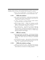
7.3.3. Gateway control
This menu is available under.
Fig. 30 – Gateway control Item of Main Menu
Login account – item for change access username and
password of the gateway.
Date / Time – gateway date and time settings. You can
synchronise the time data with your PC.
Firmware / Licence – offers two windows. The Firmware
window displays and helps upload the latest firmware version.
To find the GSM gateway firmware version press the
Load from the gate, which downloads information on the
firmware and bootware versions from the GSM gateway.
49
2N® BRI Enterprise
To upload firmware:
Establish communication with the gateway.
Click on the
button and find the firmware file in your PC
directory in the format of P2009-V-*.hex. Press Open to get the
file ready for uploading into the 2N- 2N® BRI Enterprise.
Click on
procedure.
to start the firmware uploading
The program starts uploading the firmware automatically. The
gateway is in the reset mode during the process. Do not
interrupt the firmware uploading process to avoid firmware
damage and gateway failure.
Should the firmware uploading process get interrupted, reset
the ISDN GSM gateway and try to upload the firmware again.
CAUTION! Make sure that what you are going to upload is the
original and undamaged file with the latest firmware version as
available at our websites (www.2n.cz).
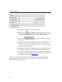
The License window helps to licence the GSM gateway. To identify the GSM
gateway status click on Load from the gate. If you require additional license,
please contact your sales person.
50
Enter the received licence into Enter license and press Enter license! button. Click
on Load from the gate! to know whether the license has been accepted
successfully.
CAUTION! By inserting an invalid license you may disable
the GSM gateway functionality.
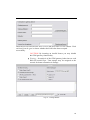
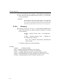
Tracing – for analysis of the GSM gateway behaviour on each
RM OSI model layer. Time stamps may be assigned to the
records for better orientation in listings.
Fig. 31 – Tracing Window
51
2N® BRI Enterprise
Terminal – the terminal window helps configuring the gateway
using AT commands.
Log file – downloads all log records from connected gateway.
Call data records – information on accomplished calls for
telephone bill control and telephone cost logging per party if
necessary.
Statistics – helps download statistic data concerning the count
of called minutes, incoming and outgoing calls, sent SMS, etc.
from the GSM gateway to the PC including saving into a file.
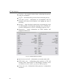
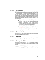
Diagnostics – shows information on GSM modules and
plugged-in SIM cards.
Fig. 32 – Modules diagnostics window
Info about actual calls – information on currently made calls.
CDR buffer state – informations about gateway’s CPU and
memory loads. Actual status of CDR memory is named: Count
of call data records: number_of_saved_CDR of capacity.
Connection state –informations about gateway’s configuration
interfaces.
52
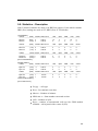
GSM monitor info – downloads actual GSM network
informations from selected GSM module (supported only
TC35i module).
Description of response parameters from TC35i module:.
Chann
Rs
ARFCN (Absolute Frequency Channel Number) of the
BCCH(THC) carrier. If chann is h BTS supports hopping
during a connection
RSSI (Received signal strength) of the BCCH carrier from
0 to 63. The indicated value is composed of the measured
value in dBm plus an offset. This is in accordance with a
formula specified in 3GPP TS05.08
dBm
PLMN
LAC
Receiving level of the BCCH carrier in dBm
PLMN ID code
Location area code (HEX)
Cell
NCC
BCC
PWR
Cell ID code (HEX)
PLMN color mode
Base station color mode
RXLev
C1
TS
timAdv
Q
Chmod
Maximal power level used on RACH channel in dBm or
current power level
Minimal receiving level (in dBm) to allow registration
Coecifient for base station selection
Timeslot number
Timing advance in bits
Receiving quality (0-7)
Channel mode (S_HR: Half rate, S_FR: full rate, S_EFR:
Enhanced full rate)
53
2N® BRI Enterprise
Test calls – for make test calls (for check voice qualitz or right
configuration). Test calls can be outgoing to GSM or ISDN
interface, or incoming). In case of proceeding call the gateway
automativally generates trace, which you can save for possible
check in case of problems.
Online commands – for sending AT command directly to
selected GSM module
Show dynamic CLIP routing table – downloads actual records
of Dynamic CLIP routing function.
Load parameters fro gateway – downloads configuration of the
gateway from the gateway to the configuration program.
Save parameters to the gateway – uploads configuration
parameters form the program to the gateway.
Gateway reset – resets the gateway.
Factory parameters reset – restarts the gateway with company
settings.
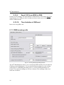
7.3.4. Setting
This menu is available under
Communication setting - helps set the type of communication
of the 2N® BRI Enterprise configuration software. By clicking
on this item you open a configuration window (see Fig. 33).
You can use a USB cable, or remote GSM (CSD) for
communication with the GSM gateway.
54
Fig. 33 – Communication Setting Window
Types of communication:
Serial communication - used for GSM gateway configuration from your PC using
a USB cable communicating via a virtual COM port at the rate of 921,600 bps,
which is selected in the Serial communication setting item. The serial
communication mode is suitable for the initial setup of the gateway. The
configuration program offers available COM ports.
Modem – used for GSM gateway configuration via GSM (CSD) modem. Be sure
to set the correct gateway dialled number and activates licence before configuring.
LAN – used for GSM gateway configuration via Ethernet / Telnet protocol.GSM
(CSD) modem. Be sure to set the correct gateway IP address, IP port and access
username+password.
LOG communication:
You can set whether and how the PC - GSM gateway communication should be
saved into a file.
Having selected the type of communication, you select the transmission rate by
clicking on Find out speed. Having found the transmission rate value, you
establish connection between the PC and GSM gateway by pressing Connect. The
Disconnect key cancels this connection. To confirm changes press OK.
Application language - sets the language used for tag names.
55
2N® BRI Enterprise
7.3.5. Help
This menu is available under (Alt + h).
About - opens a window providing information on the
configuration software version together with contacts to the
technical support personnel.
7.4. Button Bar
The button bar (
Fig. 34) displays the most frequently used commands that make the work with the
GSM gateway easier and quicker.
Exit
Terminal
Language selection
Save CFG to gateway
Load CFG from gateway
Disconnect gateway
Connect with gateway
Save CFG to file
Load CFG from file
Open templates list
Fig. 34 – BRI config program Button Bar
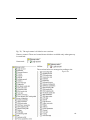
7.5. Topic List and Alphabetical Glossary
Select the more convenient of the two arrangements of configuration program
items (
56
Fig. 35). The topic menu is divided to two sections:
Gateway control: There are located items which are available only when gateway
is connected:
Connected Offilne The sections below are arranged according to the
Topic list.
57
2N® BRI Enterprise
Fig. 35 – Topic List (left) and Alphabetical Glossary (right)
8
SECTION 2
Configuration
This section describes the 2N® BRI Enterprise setting using the GSM
configuration software that is part of the installation CD supplied together with
the gateway.
This section includes:
2N® BRI Enterprise Gateway Communication Establishing
Firmware Version Identification
58
Gateway License
Load / Save Parameters
System Parameters
ISDN Parameters
ISDN port modes
8.1. ISDN port modes
Major route settings for GSM and ISDN BRI ports.
GSM parameters - General
59
2N® BRI Enterprise
GSM outgoing calls
GSM incoming calls
Prefixes
LCR table
Autorouting Table
8.2. 2N® BRI Enterprise Gateway Communication
Establishing
Select the gateway to be configured from the list of gateways available in the
Main menu, in the Gateway list tag.
Now select the type of GSM gateway connection in Setting – Communication
settings (refer to Subs.1.3.4) in the Main menu.
Having selected the communication type click on Connect gateway to establish
connection between the PC and GSM gateway.
With the GSM gateway communication type selected, connect the GSM gateway
by clicking on Connect gateway
in the Button bar.
8.3. Firmware Version Identification
If you have connected the GSM gateway for the first time, please identify the
current firmware version in the Functions – Other functions – Firmware/License
menu and compare it with the one available on our websites (www.2n.cz), or on
attached CD.
If your GSM gateway firmware version is older than that distributed by us, upload
the latest firmware version to your GSM gateway. Please follow the instructions
included in Gateway control in Subs.1.3.3. Please do not hesitate to contact out
technical support personnel in the case of troubles.
Since the product is subject to innovations please check the latest firmware
version on our websites regularly.
8.4. Gateway License
The operation of every new 2N® BRI Enterprisecan be limited to 850 hours*.
Every gateway reset reduces the remaining gateway operation time by one hour.
60
To identify the GSM gateway status use the Functions – Firmware/License menu,
for the gateway unlocking procedure refer to Functions in Subs.1.3.3.
If you require additional license, please contact your sales person.
*depends on gateway’s order number
8.5. Load / Save Parameters
Use task bar or configuration program basic menu To download configuration file
from the gateway. Upload of the configuration parameters to the gateway is
possible by similar way.
The Load from gate item (“Functions – Load parameters from gateway”)
helps download all configurable items from the gateway and save them into the
file designated during the gateway selection (refer to Subs. 1.2).
The Save to gate button (“Functions – Save parameters to gateway”) helps
upload all configurable items from the selected configuration file (refer to Subs.
1.2) to the gateway.
Load from file (“File – Load”) is used for loading an external file to the
configuration program. Structure of this file is same as of configuration file,
which was selected on gateway selection procedure, but he content is different
Save to file (“File – Save”) is used for saving of configuration to a file
designated during the gateway selection procedure.
8.6. System Parameters
Fig. 36 – System Parameter Editing Window
The System parameters card reveals settings for CDR (Call Detail Records), and
unit ID.
61
2N® BRI Enterprise
CDR mode – defines calls on which records should be made.
Data may be recorded on incoming, outgoing, successful or
unsuccessful calls, or the CDR mode can be disabled.
Unit ID – used for designation of the selected GSM gateway in
case there are more devices in the network that generate the
CDR.
System restarts – Enables automatics restarts of the GSM
gateway. For example: to prevent change PBX’s primary
synchronisation from PSTN to the GSM gateway (in cases of
PSTN 2N® BRI Enterprise restarts)
62
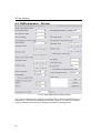
8.7. ISDN Parameters
Fig. 37 – ISDN Parameter Editing Window
The ISDN parameters card is used for setting all ISDN port parameters. To set the
gateway default values click on Default. Individual items are explained below
according to their respective groups in the editing window.
63
2N® BRI Enterprise
8.7.1. ISDN BRI port settings
Interface – adjusts the BRI interface of the gateway. This
port operates as a network termination with respect to the
other ISDN terminals on the given port. In addition to
monitoring and diagnostic functions, the GSM gateway
provides access to the D-channel and power supply to the
other ISDN terminals connected in this mode.
Port setting
Interface – NT (simulate PSTN NT) , TE (connection like
ISDN terminal)
Point-to-point – when the gateway is connected to one
device only (i.e. TE port of your PBX). It is possible to
choose fixed TEI (Terminal Endpoint Identifier)
assignment from range 0 to 63 (0 is mostly used for the
point-to-point configuration) or dynamic TEI assignment
TEI = 64 in case of point-to-point configuration. For
dynamic TEI assignment TEI is assigned from range 64
to 126. TEI = 127 is used for broadcast messages.
Point-to-multipoint – if the gateway is connected to more
terminals the dynamic TEI assignment must be selected.
DISA dial tone – Activated DISA DTMF dial tone for
second dial (used for connection on PBX extension line)
8.7.2. Tone signalling for calls to ISDN
Dial tone – with this function enabled, the GSM
gateway sends the dialtone to the NT port if the SETUP
message does not include the calling subscriber's
number..
Ring tone – selection of control ring tones which are to
be played to the caller from the ISDN network
8.7.3. Generating busy tone
To BRI for X sec – in case of activation this parameters,
busy tone will be played for X seconds after call to
GSM termination.
64
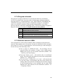
8.7.4. Progress elements
The purpose of progress elements is to describe the behaviour of terminals
involved in a connection. You can set here which progress elements should be
sent in the SETUP_ACKNOWLEDGE, CALL_PROCEEDING, PROGRESS and
ALERTING messages. Please keep the configuration settings of your PBX or
router to avoid false evaluation of the messages transmitted by your GSM
gateway and thus connection establishing errors. The decadic numbers assigned to
progress elements are included in Chyba! Nenalezen zdroj odkazů..
Number Meaning
1
The connection is not of the end-to-end ISDN type, further progress
messages will be sent in the voice band
2
The destination address is not of the ISDN type
3
The connection initiator address is not of the ISDN type
4
The connection returns to the ISDN
8
The communication of the interconnected systems led to a change of the
telecommunication service (for the end-to-end ISDN mode only)
10
Delay due to call interface failure
Tab. 5 –ISDN Cause Meanings
8.7.5. Release causes to ISDN
Cause messages are sent to those terminals whose connection request has been
rejected. They contain causes of rejection. For precise definitions of the messages
refer to the ITU-T Q.931 recommendation. You can set the type of the message to
be sent for any of the following events:
Lack of digits on OVERLAP mode – the incoming call was
rejected because the number of digits of the calling party's
dialling was too low for successful connection (default = 102
– Recovery on Timer Expiry).
Restricted number prefix – call rejection due to an unknown
prefix. The prefix does not match any item in the routing tables
(default = 21 – Call Rejected).
Selected module / GSM group is not ready – call rejection due
to the busy status of all modules that have been selected for
routing calls to the particular destination (the module assigned
to the B-channel group is not available) and no other GSM
modules have been selected for the destination (default = 41
– Temporary Failure).
65
2N® BRI Enterprise
No module / GSM group is ready – call rejection due to the
busy status of all modules that have been selected for routing
calls to the particular destination and alternative GSM modules
that have been selected routing calls to the particular
destination in case of congestion (default = 42 – Switching
Equipment Congestion).
Complete list of available release cause you find under button “?”.
8.7.6. Numbering plan settings
These parameters are for set „numbering plan“ values for Called party (CDN) and
calling party number (CGN). Please do not change it without detailed knowlodge
of ISDN DSS1 signaling.
8.7.7. Don’t send „Connect ACK“ to BRI2 – TE
Removal of the TE progress from corfirmation message in ISDN communication.
It is neccessary to use this parameter with some of Alcatel PBXes (e.g. Alcatel
4400).
8.7.8. Receive dial also from “Subaddress” element
Some ISDN terminal are sending letters “#” and “*” as Keypad facility dial mode.
With activate this parameter gateway will convert this dial to Called party
number.
66
8.8. ISDN port modes
Major route settings for GSM and ISDN BRI ports.
67
2N® BRI Enterprise
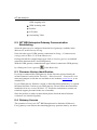
8.9. GSM parameters - General
Fig. 38 – Basic GSM Parameter Editing Window
This section contains basic settings for routing calls to the external GSM ports of
the gateway. The Default button sets the default values. The “Advanced” button
offers possibility of advanced GSM general parameters configuration.
68
8.9.1. Number of figits dialed from ISDN
Min. numbers from ISDN – minimal count of digits recieved on
ISDN inteface needed for establishing of the call to the GSM
network. If the count of digits is lower than the value in this
field the connection to the GSM network will not proceed.
Max. numbers from ISDN – maximal count of digits received
on ISDN interface that will be accepted for establishing of the
connection to the GSM network. If the count of digits is higher
than the value in this field the connection to the GSM network
will continue using first n digits, where n is the value in this
field.
Wait for next digit [s] – a timeout during which the GSM
gateway waits for another digit of the subscriber dialling. After
this timeout, if the count of received digits is sufficient, the
gateway tries to make connection.
8.9.2. SIM cards PIN code number
SIM cards PIN number – enter the PIN code to be entered
automatically for new SIM cards. The PIN codes of all inserted
SIM cards must be same.
8.9.3. GSM Module selection
There is possible to set the way of GSM modules to B-channels assignments for
outgoing calls in this section. Use the menu to choose one of the following
possibilities:
Cyclic – GSM modules alternate after each call
Locked – outgoing calls on B1 channel are routed through
GSM1 module and outgoing calls on B2 channel are routed
through GSM2 module.
Smart – calls are routed through the module that has less
called minutes in statistics.
69
2N® BRI Enterprise
8.9.4. Signalling tones for calls to GSM
Dialtone to NT interface on empty SETUP – this menu sets
the type of dialling tone generated to the NT interface by
GSM gateway on receiving SETUP message without called
party number field
Ring tone - in this menu is possible to select the type of
ringing tone generated by the GSM gateway when calling to
the GSM network
8.9.5. Relax delay
Time delay between two calls to the GSM network. Establishing
of new call to GSM network thru the same GSM module is
possible after expiry of this timeout. The GSM module clears the
call to GSM network during this time. The optimum value is
about 2 s.
8.9.6. DTMF Delay
Delay [1/100 s] – sensitivity of DTMF receiver from GSM network. Parameter
“delay” means 10*miliseconds which is added to default value 20ms. The total
time is minimal delay between two DTMF chars. Example: DTMF number=30
delay=30*10+20=320.
8.9.7. SIM card number
In this section is possible to define which SIM card number
should be used in the GSM gateway:
IMSI – International Mobile Subscriber Identity
SCID – SIM Card Identification Number**
8.9.8. Don’t send CLIP
By enabling this function you deactivate transfer of calling party number (CLIP)
from GSM to ISDN. In case, that this parameter will be switched off, CLIP from
GSM will be forwarded to ISDN.
**
supported by Siemens GSM modules only
70
8.9.9. Modules settings
This section is dedicated for adjusting of GSM/3G modules only:
|-> for audio signal from GSM/3G network amplification
->| for audio signal to GSM/3G network amplification
Allow Siemens tone – this function allows to send tones
generated by Siemens GSM module while establishing
connection to GSM network
Use networks – Select type of network which will be used after
start of GSM/3G module.
Searching priority – Select type of network which will module
looking for after start.
71
2N® BRI Enterprise
8.10. GSM outgoing calls
Fig. 39 - Editing Window of GSM outgoing parameters
The 2N® BRI Enterprise allows you to setup both GSM modules for call to the
GSM network independently. You can select different settings for each of them
with respect to establishing connections, count of called minutes and sent
72
messages within a period. To set the default parameters use Default. For advanced
settings use Advanced button. The meanings of the card items are as follows:
Same setting as GSM module 1- this checkbox sets the same
parameters for GSM module 2 as on the GSM module 1 fold
8.10.1.
GSM calls statistics
Max. number of called minutes – defines the maximum number
of minutes called within a moth through the given SIM card.
This parameter is ignored if 0 is selected.
“Minute” parameter- is used for setting up whether statistics
are counted in minutes or in number of calls.
SMS messages number – defines the maximum possible
number of SMS messages sent within a month from the given
SIM card. This parameter is ignored if 0 is selected.
Day of deleting stats. – sets the day in a month on which the
statistic data on Max. number of called minutes and SMS
messages number are deleted. This parameter is ignored if 0 is
selected. By setting this parameter to value „32“ enables dayly
deleting of statistics after midnight.
8.10.2.
SMS at no answer
Default delay before send SMS [s]: - time interval of timeout
for sending SMS when the called party in GSM network
doesn’t answer the call. Value “0” disables SMS at no answer
function. The timeout starts after receiving of ALERTING
message.
Text for SMS at no answer – enter text that will be send when
the called party in GSM network doesn’t answer the call. The
string “%N“ is replaced by the CLIP of SIM card.
8.10.3.
GSM calls statistics settings
Number of seconds after connect – the length of the first pulse
after which pulses are counted according to the value included
in the Number of seconds for next counting parameter.
73
2N® BRI Enterprise
Nr. of seconds for next counting – the number of seconds per
pulse after the timeout defined in the Number of seconds after
connect parameter.
Example:
If, from the viewpoint of the GSM provider, a call shorter than
60s is billed as a 60s call, set the Number of seconds after
connect at 60s. If the GSM provider bills calls in seconds after
the first 60s, set the Number of seconds for next counting at 1 s.
8.10.4.
Roaming
Roaming enabled for network – an international identification
code of the network for which roaming is enabled. It consists
of two numbers:
MCC – Mobile Country Code – Czech Republic 230)
MNC – Mobile Network Code – T-Mobile 01,
Telefónica 02, Oskar 03
Thus, the T-Mobile International Identification
Code is 23001.
To disable roaming leave this field blank.
Example:
- <empty>
...roaming restricted
- 2300 ...roaming restricted (minimum is five digits)
- 23002 ...roaming enabled only to network code 23002
- 230Xx ...roaming enabled to network codes from 23000 to 23099
- xX001...roaming enabled with codes which has last three digits = 001
- xXXxX...roaming enabled to ANY GSM/3G network code
74
8.10.5.
CLIR function
CLIR – This parameter defines whether or not the calling SIM
card telephone number shall be displayed to the called party. It
is not recommended to present the telephone number of the
SIM card inserted in the GSM module to the called party to
avoid problems with calling back. It is impossible for technical
reasons to transmit telephone numbers of ISDN terminals to a
GSM network. One of the following parameters can be set for
each GSM group:
Default – default settings of the GSM provider.
Disable (CLIP on) – the SIM card telephone
number is transmitted to the GSM network.
Contact your GSM provider for activation of this
service if it is not supported automatically.
Enable (CLIP off) – the SIM card telephone
number is not transmitted to the GSM network.
CAUTION! Some GSM providers do not support
this function, which might lead to rejection of an
outgoing call.
8.10.6.
Disconnect call
Disconnect call – the currently made call is disconnected in
cases included in the pull-down menu.
8.10.7.
Statistics
Day of deleting stats in group – defines the day on which
statistic data on disconnected calls are deleted.
8.10.8.
Messages to ISDN
Delay before send CONNECT [s] – a delay before sending
information on a connected call after reception from the GSM
network.
Delay for ALERTING [s] – timeout for generating of
ALERTING message by the GSM gateway in case the gateway
does not receive ALERTING message from GSM network
75
2N® BRI Enterprise
8.10.9.
Send CLIP from ISDN to GSM
Feature for forwarding CLIP from ISDN to GSM network. This feature MUST be
supported by your GSM provider! In otherwise there can be reject of outgoing
calls to GSM network!
8.10.10.
Time limitation of SIM card
Interval of using SIM card.
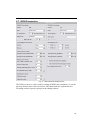
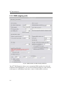
8.11. GSM incoming calls
Fig. 40 - Incoming GSM Group Editing Window
The 2N® BRI Enterprise allows you to setup both GSM modules for call from the
GSM network independently. You can select different settings for each of them
with respect to establishing incoming calls. To set the default parameters use
Default. For advanced settings use Advanced button. The meanings of the card
items are as follows:
76
Same setting as GSM module 1- this checkbox sets the same
parameters for GSM module 2 as on the GSM module 1 fold
8.11.1.
Mode
Set the way the GSM gateway shall process incoming calls from
the GSM network.
Reject incoming calls – all incoming calls from the GSM
network are rejected automatically.
Ignore incoming calls – all incoming calls from the GSM
network are ignored automatically. The calling subscriber
hears the ringing tone.
Receive incoming calls + voice message – incoming calls
from the GSM network are received and, if defined so,
the DTMF with a voice message is enabled for the
incoming call.
Receive incoming calls + dialtone – incoming GSM calls
are received incoming calls from the GSM network are
received and, if defined so, the DTMF with a simulated
dialtone is enabled for the incoming call.
CallBack after ring / Reject – in case the CLIP is
included in the CallBack table, a CallBack is made. The
GSM gateway rejects the incoming call and makes an
automatic CallBack.
CallBack after ring / Ignore – in case the CLIP is
included in the CallBack chart, a CallBack is made. The
incoming call is ignored. If the calling subscriber does
not hang up within the defined timeout (default = 10s),
the CallBack function is ignored and the call is processed
normally (refer to Subs. 1.5).
Report to PC + voice message – the GSM gateway sends
information on an incoming call to the PC equipped with
the call routing software. The DTMF with a voice
message may be enabled for the incoming call.
77
2N® BRI Enterprise
Report to PC + dialtone – the GSM gateway sends
information on an incoming call to the PC equipped with
the call routing software. The DTMF with a simulated
dialtone may be enabled for the incoming call.
8.11.2.
DISA DTMF digits
Minimum digits in DTMF - the minimum number of digits
required by the gateway in the DTMF.
Maximum digits in DTMF - the maximum number of digits
accepted by the gateway in the DTMF.
Timeout while inputing DTMF digitst [s] – a timeout during
which the GSM gateway waits for the first / another DTMF
digit. If 0 is selected, the incoming call is connected
automatically to the numbers included in the List of called
numbers.
8.11.3.
CLIP
Replace “+” by expression - the '+' character from the CLIP
is replaced with a sequence of digits included in this field.
Example:
Calling party identification (CLIP) is +420602123456
a)
“Replace „+“ by expression“: {empty}
CLIP sent to the PBX is: 420602123456
b)
“Replace „+“ by expression“: +
CLIP sent to the PBX is: +420602123456
c)
“Replace „+“ by expression“: 00
CLIP sent to the PBX is: 00420602123456
8.11.4.
List of called numbers
The list of called numbers, which will be called to ISDN
network in case that an incoming call from GSM network will
not contain correct called party number or the timeout Wait for
next digit [s] expires. Numbers are dialed down from top.
78
8.11.5.
Dynamic CLIP routing settings
Record validity [h]: - for time validity of record in dynamic
CLIP routing table. Value “0” disables this function.
Dynamic CLIP routing allows to route calls from GSM
network directly to the extension, which was the last time
connected with the GSM network user.
Create record for unconnected calls only – sets saving of
unconnected calls to the dynamic CLIP routing table. The
record will be added in case the call was is not connected
only
Erase record after using – setting of this parameter enables
deleting of the record from the dynamic CLIP routing table
after the call connection.
8.11.6.
Day of deleting statistics
Defines a day in a month on which statistical data on incoming
calls are deleted. By setting this parameter at 0 you disable this
function.
8.11.7.
Prefix before DISA
Prefix before DISA – a digital prefix to precede the DTMF
automatically.
8.11.8.
Looping of voice message
Voice message loop [min]: - DISA for incoming calls is
repeated for time interval filled in this field in minutes.
Value “0” for playback DISA record only once.
8.11.9.
Recognition CDN in CLIP
Specifics function for some GSM networks which support transfer of additional
informations about in CLIP field.
79
2N® BRI Enterprise
8.12. Prefixes
Fig. 41 - Network List Editing Window
The List of prefixes helps the gateway connect calls to various GSM networks.
You can define call routing by prefixes in eight groups. Default sets the current
list to default settings. Default all sets all prefixlists to default setting. You will
find the following items in the editing window:
Table of replaced prefixes – a table of prefixes to be replaced
(e.g. '+420' with '0'). This change is made before the prefix
table is checked.
Table of prefixes – a table of called prefixes. You can define
the dialling length too here. If you do not enter the dialling
length, the Default count of digits will be used automatically.
GSM network ID – a numerical identification code of the
selected prefix table used for internal identification purposes
only. It has no influence on call routing.
Default count of digits – used for defining the count of digits to
be considered if the count is not included in the prefix table.
80
8.13. LCR table
The LCR (Least Cost Routing) table helps define the call routing procedure
according to the called subscriber's number depending on the day time and day in
a week.
The LCR table setting using the GSM configuration software is discussed in this
subsection.
Fig. 42 – LCR table
LCR Table
Add – this button adds a record into the LCR table. By pressing
it you open the editing window (see Fig. 43).
81
2N® BRI Enterprise
Fig. 43 – LCR table Data Entering
By completing the LCR data adding table you set one call routing rule.
Prefix list – select one of the prefixlists from the “GSM
Parameters – Prefixes” in the pull-down menu to which
the routing rule should apply. The prefixlist settings are
discussed in Subs. 1.12.
Outgoing interface – this list is used for selecting of
outgoing interface. All outgoing calls are routed to the
respective interface according to the selected prefixlist.
The routing priority is from top to bottom. Therefore, if
the top parameter (GSM module 1) cannot be used, the
call is routed according to the parameter under the first
one (GSM module 2). Setting of routing according to Any
group/module is required if the parameter GSM
parameters – General – GSM module selection is set up to
Cyclic or Smart. Use ISDN TE interface to set up routing
of calls to TE port according to prefixes in Prefixlist.
Time limitation of use– sets the time limit for the routing
rule defined in this menu. The time validity From – To
may include weekends too.
82
Max. length of call – limits the call duration to the network
selected in Network number through the GSM group
selected in Groups. To disable the call duration limitation
set the value at 0.
Edit – you can edit a routing rule from the LCR table by
pressing this button.
Remove – deletes a routing rule selected from the LCR table
list.
Holiday List
Holidays list – enter the public holidays to optimise your
telephone costs with the LCR.
Date to move to summer time [dd:mm] – enter the day on
which winter time should be changed into summer time for
LCR purposes.
Date to move to winter time [dd:mm] – enter the day on which
summer time should be changed into winter time for LCR
purposes.
8.14. Autorouting Table
Autorouting table is a tool for permanent routing of incoming calls from GSM
network to respective extensions. Moreover the Autorouting table serves for
managing of Callback function for incoming CLIPs from GSM network.
83
2N® BRI Enterprise
Add – this button is intended for adding of new record to the
autorouting table. The window shown on the opens by clicking
this button.
GSM number (CLIP) – field for the GSM number, for which
will be autodial or autocallback function applied. CLIP must be
entered in the same format as is presented by GSM network
(the same as is for incoming calls shown on GSM phone
display).
Dial (to ISDN) – incoming GSM calls will be routed to the
ISDN extension number filled in this field
Autodial – selecting this item all incoming calls with CLIP
filled in GSM number (CLIP) will be routed to the extension
number filled in Dial (to ISDN) field.
Autocallback – selecting of this item activates Autocallback
function. The autocallback routine is activated after the calling
party in the GSM network hangs up. If the field Dial (to ISDN)
is filled in, the BRI Enterprise establishes connection to the
extension in the ISDN network while establishing of the call to
the GSM network. If the Dial (to ISDN) field is empty, the BRI
Enterprise establishes connection back to the GSM and after
the accepting of the call plays back the dial tone or voice
message and awaits DTMF digits.
Limit – setup the maximum length of call. Value “0” disables
this function.
Edit – for editing of autorouting table records. Clicking this
button opens the window shown on Chyba! Nenalezen zdroj
odkazů..
Remove – for removing of autorouting table records. Clicking
this button removes selected record from the table.
84
9
SECTION 3 –
Configuration Using Terminal
It is possible to communicate with the 2N® BRI Enterprise through a USB. The
connection allows for a uniform way of gateway configuration using AT
commands.
This section includes:
USB Communication Settings
LAN Communication Settings
Transmission rate:
Data bits:
8
Parity:
none
Stop bits:
1
Flow control:
none
921600 bps
9.1. LAN Communication Settings
To communicate with the 2N® BRI Enterprise gateway through the LAN, set the
LAN IP address first. To do this you need a direct USB PC connection. You can
use such programs as HyperTerminal, Putty, etc. for communication.
IP address:
gateway address set by you
85
2N® BRI Enterprise
Port:
23
The gateway requires username „USER“ and password „PASSWORD“ for login.
The gateway responses with “OK” message after the entering of correct
identification data.
Terminal Communication
List of Terminal AT Commands
9.2. USB Communication Settings
You can, e.g., use the HyperTerminal communication software for communication
using a USB port connected as a virtual COM port. To set communication select
the following parameters:
Transmission rate:
921600 bps
Data bits:
8
Parity:
none
Stop bits:
1
Flow control:
none
9.3. LAN Communication Settings
To communicate with the 2N® BRI Enterprise gateway through the LAN, set the
LAN IP address first. To do this you need a direct USB PC connection. You can
use such programs as HyperTerminal, Putty, etc. for communication.
IP address:
gateway address set by you
Port:
23
The gateway requires username „USER“ and password „PASSWORD“ for login.
The gateway responses with “OK” message after the entering of correct
identification data.
9.4. Terminal Communication
The terminal is also part of the GSM configuration software. To start the terminal
use Functions – Other functions – Terminal from the main menu. Be sure to
configure the GSM program properly for communication (refer to Subs. 1.3,
Functions).
86
9.5. GSM Gateway Behaviour
The gateway behaves like an ANSI terminal with an echo. The commands are
entered in the text format and the X-modem protocol is used for file transfer. The
gateway responses with the “OK” message after the login to the gateway. If not,
type: at and press <ENTER> key. In case the gateway is correctly connected, the
gateway responses by the „OK“ message. There is possible to set username and
password to ensure better security of the gateway. The gateway responses with the
message shown in the Fig. 44 if the login name is required. After entering of your
login name press <ENTER> and after that enter the password.
Fig. 44 – Login message
9.6. List of Terminal AT Commands
All commands start with AT by default. (Note: Some of the below mentioned AT
commands may not be available in the current firmware versions.)
Note: AT commands are same as for BRI Enterprise gateway. Commands which
contains BRI1 (Pxx) settings are not used in 2N® BRI Enterprise gateway. 2N®
BRI Enterprise gateways has only BRI2 (Exx) interface.
Basic AT Commands
A/
I3
...repeat last command (without AT)
...copyright & firmware
I4
&FRES
...serial number
...factory defaults & reset
&V
&VI
...view active parameters (system)
...view active parameters (isdn)
&V0
&V#
...view active parameters (common)
...view active parameters (modules 1..2)
&V9
&VALL
...view active parameters (inc. groups)
...view all group parameters
&P
&N#
...view pseudo params
...view network params (net 1..8)
&NALL
&A
...view all network params
...view autorouting table <SPACE...continue>
87
2N® BRI Enterprise
&R
&T
...view lcr-routing table <SPACE...continue>
...view bris + modules totals
&TMOD
&G##=atcommand
...view all modules totals
...send at command to module 0..1 (ended by OK from gsm)
&G##=xtcommand
&G##=cmd
...send at command to module 0..1 (ended by <CR> from user)
...cmd for module 0..1 (RESET,BLOCK,OFF,DOWN,ON), (ATBAUD)
&GALL=cmd
&S
...cmd for module 0..1 (RESET,BLOCK,OFF,DOWN,ON)
...view aux, bris, modules status
&S##
&S=info
...view aux, bris, one module status (ax,px,ex,0..1)
...view all modules selected info (by at&S##)
&Q##
&QALL
...view signal quality on module 0..1
...view signal quality on all modules
&L
&C
...view logfile from recent <SPACE...continue>
...view buffer (calls) from recent <SPACE...continue>
&CR
&BSYS=cmd
...read buffer from the oldest <#...erase & continue>
...cmd for system (RESET)
&XG
(&XG##
...view conn table/gsm (call states)
...view call details for gsm channel)
&M0
&M1
...disable ansi colors
...enable ansi colors
&M9
&U
...start matrix
...view logged users
&I##
...view gsm moninfo (dBm = siganl level whn registering with BTS,
RxLEV = minimum signal level required by BTS for registering of GSM module)
Configuration AT Commands
System Settings
%S85=sms
%S90=mode
...no answer sms text (max 63 chars)
...operating mode of GSM module allocation
(0=cyclic mode, 1=locked mode, 2=smart mode - according to already called minutes)
%S91=buf,id
(for 0 and 2 set LCR group = 3 (any))
...cdr mode (b0=outg, b1=inc, b2=failed, b3=moninfo)
%S92=rep
unit id (0=off, 1..255)
...report mode (b0=states, b1=tstamp, b2=smp,
%S98=pin
b3=lay2, b4=select)
...sim pin (max 7 digits)
%S99=dd.mm.yy.w/hh:mm:ss
%X10=tsec
...set date/time (w=1..7 day of week)
...external routing tout in sec/10 (5..60,255)
%X20=mmdd,mmdd
...date of hour+1,hour-1 time change (0=off,0101..1231)
88
%X22=hh:mm
%X80=login/pass
%X40=GSM,BRI1,BRI2,0
...0:01..23:59 - time of reset of GSM gateway, 0:00 - no reset
...login name / password (max 15 chars all)
… basic port routing:
GSM=0 incomming GSM call rejected
GSM=1 incomming GSM calls will be routed to BRI1
GSM=2 incomming GSM calls will be routed to BRI2
BRI1=0 all calls from BRI1 will be rejected
BRI1=2 all calls will be routed to BRI2
BRI1=G routing to GSM by LCR table
BRI1=A routing to GSM by LCR table, then BRI2
BRI2=0 all calls from BRI1 will be rejected
BRI2=1 all calls will be routed to BRI1
BRI2=G routing to GSM by LCR table
BRI2=B routing to GSM by LCR table, then BRI1
System Control
AT&Gxx=RESET
Reset of GSM module No xx
AT&Gxx=BLOCK
Block of GSM module No xx
AT&Gxx=DOWN
Transfer of GSM module into the sleep mode
AT&Gxx=ON
Transfer of GSM module into the idle mode
ISDN Settings
%I00=xxx
...BRI protocol mode
= NT : as Network termination mode
= NT/S : Network termination mode with activated external synchronisation on TE
mode
= NT/O : Netwrok termination mode with activated internal ISDN clock generator
= TE/E : as TE mode with DTMF receiving (extension)
= TE/T : as TE mode without DTMF receiving (trunk)
%I01=tei,mtp
tei,mtp = 0..63,0 ….fixed tei,ptp
tei,mtp = 64,0 ….dynamic tei,ptp
%I05=c1,c2,c3,c4
tei,mtp = 64,1
....fixed tei,mtp
...cause codes for failed calls
c1=dial timeout (TIMEOUT=120)
c2=dis.prefix (REJECT=21)
c3=req.mod/grp not ready (TEMPFAIL=41)
c4=pref grps not ready (CONGEST=42)
89
2N® BRI Enterprise
%I06=sack,proc,prog,ale
%I07=opx/npx,...
%I08=dial,ring,disc
%I09=day,bits,enb
...prog.elem (0=off,1..8) for isdn message
...list of old/new prefixes (max 47 chars)
...dial (0 = off,1..255) dialtone to NT on empty SETUP, ring (0=off,1 ..255) ringtone
to NT if no PROGRESS from PSTN
- 1=EU (dial = constantly 425Hz,
ring = 1000+4000msec 425Hz)
- 2=CZ (dial = 300/300/600/1200msec 425Hz, ring = 1000+4000msec 425Hz)
- 3=HU (dial = constantly 425Hz,
ring = 1000+4000msec 425Hz)
- 4=GB (dial = constantly 425Hz,
ring = 400+200+400+2000msec 400+450Hz)
disc(0=off,1..255) busytone to NT interface on DISCONNEECT
...day (0=off,1..31) of clearing bri stat
ctrl bits (b0=not defined, b1=not defined ,b2=subaddr-recv, b4=don't send
CONNECT_ACK in TE mode)
enblock digits (0=overlap,1..20)
%I127=msn
...MSN number for TE mode
GSM / Groups settings
%G02=mode,atms,afms
...tc35 mode (2,4)
atms/afms gain (+5dB=3,+2.5dB=1,0dB=0,-2.5dB=2,-5dB=4)
%G05=delay
...dtmf space delay (1..99 sec/100)
...holiday list (0101=1st jan, 1231=31st dec)
%G06=mmdd,..mmdd
%G07=mmdd,..mmdd
%G08=delay,min,max,tout
...holiday list2
...gsm call delay (0..10 sec), dial min/max (0..20)
%G09=bits,dial,ring
dial tout (0..20 sec)
...bit0=sim card number (0=imsi,1=scid)
bit1=siemens connecting tone,
bit2=don't send CLIP for calls BRI<-GSM
bit3=send AoC for calls BRI->GSM (functionless for FW>2.03.14 and lower)
dial (0=off,1..255) dialtone to GSM, ring(0=off,1..255) ringtone to GSM if no
PROGRESS from PBX
- 1=EU (dial = constantly 425Hz,
ring = 1000+4000msec 425Hz)
- 2=CZ (dial = 300/300/600/1200msec 425Hz, ring = 1000+4000msec 425Hz)
- 3=HU (dial = constantly 425Hz,
ring = 1000+4000msec 425Hz)
- 4=GB (dial = constantly 425Hz,
ring = 400+200+400+2000msec 400+450Hz)
%G101=old/new,...
...gsm causes change table (0..8 causes)
%G#1=netid,clir,min,sms,day,sec,sec2,pseudo
...out.module 1..2, sim 1 params
netid (7 chars), clir (0=netw,1=on,2=off)
min (0=0ff,1..65535 minutes), sms (0=off,1..65535)
day (0=off,1..31,32=everyday), sec/2 (1..250)
pseudo (0=off,1..8)
%G#9=ale,conn,disc,day,bits,nasms
90
...alerting tout (0=off,1=send ALERTING on recieveng +CIEV form GSM network,
2..20sec after recieving PROCEEDING)
conn delay (0..20sec),
forced disc (bit0=sim limit, bit1=time limit, bit2=noale)
day (0=off,1..31) of clearing group stat,
bits 0..255, b0=(notused), b1=min-->calls, b2=(notused)
b3=(notused),
nasms tout (0=off, 1..20sec)
%G9#=mode,min,max,tout,day,dial,clip
...inc.module 1..2 params
mode (0=reject,1=ignore,2=ok-message,3=ok-tone)
mode (4..7=0..3 + autocallback, 6..7= + ext.callback)
min(0..20), max(0..20) tout (0..20 sec) dtmf dial-in
day (0=off,1..31) of clearing inc.group stat
dial prefix (max 15 ch), clip prefix (max 7 ch)
%G9#=xxx,xxx,...xxx
%G99=exp,bits
...auto dials (max 63 chars) #=5..8 for inc.groups 1..4
...dynamic clip expire (0=off,1..240 hours)
%G19#=mess
bit0=add.conn, bit1=rem.answ
...params #=1..4 for inc.groups 1..4
mess duration (0=once, 1..99=repeated) minutes
Pseudo paramaters
%P01=uuu/HH:MM,...
...pseudo tarif 6x cents/until (cents=1..9999)
(until=00:00...first item is all weekend)
(until=24:00...last mandatory item)
%P02=uuu/HH:MM,...
%P03=uuu/HH:MM,...
%P04=uuu/HH:MM,...
%P05=uuu/HH:MM,...
%P06=uuu/HH:MM,...
%P07=uuu/HH:MM,...
%P09=mode,sec
...pseudo tarif extension
...pseudo tarif extension
...pseudo tarif extension
...pseudo tarif extension
...pseudo tarif extension
...pseudo tarif extension
...pseudo mode (0=off,1=cdr,2=cdr+isdn), isdn.sec (1..250)
Networklist Parameters
%N#0=opx/npx,...
%N#1=pref/dig,...
%N#2=pref/dig,...
%N#3=pref/dig,...
%N#4=pref/dig,...
%N#5=pref/dig,...
%N#6=pref/dig,...
...list of old/new main-prefixes (max 47 chars)
...list of prefixes/digits-to-end (max 63 chars)
...pref. list extension (max 63 chars)
...pref. list extension (max 63 chars)
...pref. list extension (max 63 chars)
...pref. list extension (max 63 chars)
...pref. list extension (max 63 chars)
91
2N® BRI Enterprise
%N#7=pref/dig,...
%N#9=netid,max
92
...pref. list extension (max 63 chars)
...network id (7 chars), default max digits (0..20)
Routing Paramaters
%A##=clip,dial,limit
...set autorouting item (ix 0..95)
clip (20), dial(20), limit(0=off,1..99 minutes)
%R##=net,hh:mm/hh:mm/w+-,groups,lim ...set lcr-routing item (ix 0..63)
net (1..8), groups = (max 7 chars=1..3,9), 3=any module, 9=bri2
call limit (0=off, 1..99min)
last LCR table line must be empty
; totals
; first m,c,s
; second m,c,s
; ri,ro
%TB#=m,c,m,c
%TBALL=m,c,m,c
%TG#=m,c,ri,ro
%TGALL=m,c,ri,ro
%TI#=m,c
%TIALL=m,c
%T##=1,m,c,s,m,c,s
%TALL=1,m,c,s,m,c,s
...inc. minutes,calls,smses
...out. minutes,calls,smses
...redirected inc,out calls
...init minutes,calls in bri # (0..65535)
...init minutes,calls in all bris (0..65535)
...init minutes,calls,rin,rout in group # (0..65535)
...init minutes,calls,rin,rout in all groups (0..65535)
...init minutes,calls in inc.group # (0..65535)
...init minutes,calls in all inc.groups (0..65535)
...init minutes,calls,sms in mod ##, sim 1 (0..65535)
...init minutes,calls,sms in all mods, sim 1 (0..65535)
Tracing commands
AT!RE
Start tracing of error messages active interface.
AT!Lx
AT!RR
Start tracing of LAN & Telnet on layer x
x=2 – Layers IP,TCP,Telnet
x=3 – Layers TCP, Telnet
x=4 – Layer Telnet
Start tracing of ISDN BRI & GSM on layer x
x=1 – Layers 1,2,3,4
x=2 – Layers 2,3,4
x=3 – Layers 3,4
x=4 – Layer 4
Start tracing (AT!R2) to COM interface
AT!RX
Stop tracing (AT!R2) to COM interface
AT!Rx
93
2N® BRI Enterprise
Work with SMS
SMS sending and receiving commands
AT!G=A6
AT!G=55
Start low-level controlling for SMS (can run only on one port)
Stop low-level controlling on used port
Control SMS
…(sms listing) request to list all SMS messages and status confirmations
saved on SIM card. Possible answers:: *smserr (busy,list) or *smsinc
(ix=1..255) for each saved SMS or status SMS messages, end of list or empty
SIM card - *smsinc (ix=0).
…(sms read) request to read SMS or status SMS saved in SIM card. Possible
AT^SR=ch,ix
answers: *smserr (busy,read) or *smspdu
…(sms delete) request to delete SMS message (or status SMS message).
AT^SD=ch,ix
Possible answers: *smserr (busy,delete) or *smsdel
AT^SM=ch,len,pdu,csum …(sms to module) request to send message via GSM module 0..31 or via any
GSM module (ch=32). Possible answers: *smserr (busy,write) or *smsout
AT^SG=grp,len,pdu,csum …(sms to group) request to send SMS message via GSM group 1..8.
Possible answers: *smserr (busy,write) or *smsout
AT^SX=ch
Messages from BRI ISDN Gateway
*smsinc: ch,ix,sts
*smsrep: ch,ix
*smsout: ch,ix,ref
*smspdu:
ch,ix,sts,len,pdu,csum
*smsdel: ch,ix
*smserr: ch,ix,req,err
94
… SMS message was received and saved into SIM card:
Ch
…GSM module number 0..31
Ix
…index number of saved SMS 0..255
Sts
…SMS status
…SMS status confirmation was received and saved to SIM card (this
message is only for GSM modules TC35 and GM47)
…SMS message was sent and was not saved into SIM card:
Ref
…reference number of sent SMS 0..255 (will be used in SMS status
confirmation message)
…content of SMS message or status confirmation:
Len
…SMS length (number of bytes in PDU)
Pdu
…message content in PDU format
Csum …Checksum of all PDU bytes (2 hexa digits) calculated without
carry
SMS message or status confirmation was deleted from position ix
response to error command:
Req
…required GSM module or GSM group
Err
…error code (6=busy, 40=write, 41=read, 42=delete, 43=list)
95
2N® BRI Enterprise
Status Messages
ISDN Layer 1 Status Messages
ID
0
1
2
3
Name
DEACT
ACTIVE
SIGNAL
SYNC
Description
Deactivation – no signal received
Activation – full synchronisation achieved (frame,multiframe,crc)
Signal received – no synchronisation
Signal received – only partial synchronisation (frame)
ISDN Layer 2 Status Messages
ID
0
1
2
3
4
5
6
7
Name
NOTEI
AWTEI
AWTEST
OKTEI
AWEST
AWREL
OKEST
TIMREC
Name according to ITU-T Q.921
TEI Unassigned
Assigned Awaiting TEI
Establish Awaiting TEI
TEI Assigned
Awaiting Establishment
Awaiting Release
Multiple Frame Established
Timer Recovery
ISDN Layer 3 Status Messages
ID
0
1
2
3
4
6
7
8
9
10
11
12
19
25
61
62
Name
NULL
CINIT
OVSEND
OPROC
CDELIV
CPRES
CRECV
CONREQ
IPROC
ACTIVE
DISREQ
DISIND
RELREQ
OVRECV
RSTREQ
RSTART
Name according to Q.931
Null
Call Initiated
Overlap Sending
Outgoing Call Proceeding
Call Delivered
Call Present
Call Received
Connect Request
Incoming Call Proceeding
Active
Disconnect Request
Disconnect Indication
Release Request
Overlap Receiving
Restart Request
Restart
Description on NT interface
Rest status, ready for call
Call from BRI indicated
Gradual dialling receiving
Dialling from BRI terminated
Call from BRI ringing
Call to BRI started
Call to BRI ringing
Call to BRI answered
Dialling to BRI terminated
Connected call
End of call from BRI
End of call to BRI
Channel release request
Gradual dialling sending
Channel restart request sent
Channel restart request received
Management Status Messages
ID
0
1
2
96
Name
INIT
IDLE
DISC
Description
Initialisation upon BRI reset
Activation – rest status, necessary for layers 2 and 3
Deactivation
Description on TE interface
Call to BRI started
Gradual dialling sending
Dialling to BRI terminated
Call to BRI ringing
Call from BRI indicated
Call from BRI ringing
Call from BRI answered
Dialling from BRI terminated
End of call to BRI
End of call from BRI
Gradual dialling receiving
GSM Layer Statuses
GSM Layer 2 Status Messages
ID
0
1
2
3
4
5
6
7
8
9
10
13
Name
INIT
SIM0
PINREQ
PINSET
BLOCK
SETUP
SLEEP
NWAIT
IDLE
CALL
CMD
INFO
Description
GSM module initialisation start
Module switch to internal SIM card
Module PIN request
PIN value sending to module
Module blocked temporarily or permanently (see Layer 2 information)
Module configuration running
Module sleep running (transition to BLOCK status)
Awaiting GSM log-in
Rest status, can start/receive call, execute AT&G command
Call running (call establishing, connected call, call end)
Communicating with module upon AT&G command
Information loading from module and SIM card
Followed by
PINREQ
INIT
PINSET
INFO
INIT
IDLE
BLOCK
SETUP
CALL/CMD
IDLE
IDLE
NWAIT
GSM Layer BLOCK Status Messages
ID
41
42
43
44
45
46
47
48
Name
(block)
Netw-reg
Clir-err
Mod-err
Pin-err
Sim-err
Log-out
Puk-req
(undef)
Description
Blocked by AT&G command, terminated by module, board or system reset
GSM log-in refused (not activated SIM), next attempt in 5..60 minutes
CLIR activation request refused, next attempt in 2..10 minutes
Defective or not connected GSM module, next attempt in 2 minutes
Wrong PIN, permanently in BLOCK status
Defective or not inserted SIM card, next attempt in 2 minutes
Temporarily logged-out according to parameter X00
SIM card requires PUK
This position of SIM card wasn’t checked by gateway
GSM Layer 3 Status Messages
ID
0
1
3
4
6
7
9
10
11
12
19
25
38
Name
NULL
CINIT
OPROC
CDELIV
CPRES
CRECV
IPROC
ACTIVE
DISREQ
DISIND
RELREQ
OVRECV
RELIND
Description
Rest status, ready for call
Call request to GSM (from Layer 4)
Call to GSM is connected
Call to GSM is ringing
Call indication from GSM (from Layer 2)
Call from GSM is ringing on ISDN interface
Call from GSM is processed by ISDN interface
Connected call
Disconnection request (to Layer 2)
Indication of disconnection (from Layer 2)
Module release for another call (to Layer 2)
Reading of DTMF dialling from GSM (from Layer 2)
Indication of module release (from Layer2)
97
2N® BRI Enterprise
Layer 4 Status Messages
ID
0
1
2
3
4
5
98
Name
NULL
MORE
SETUP
PROC
ACTIVE
DISC
Description
Rest status, ready for call
Call request received from GSM or ISDN, awaiting further dialling or timeout
Call request sent to opposite interface
Call request confirmed, awaiting call answer
Connected call
Call disconnection in progress
Command Shell Statuses
Command Line Status Messages
ID
0
1
2
3
4
5
6
7
8
9
10
11
Name
IDLE
REQUEST
REPORT
LOGFILE
CALLFILE
CALLREAD
AUTOFILE
QUERY
SCREEN
MATRIX
FUNCFILE
LCRFILE
Description
Rest status, awaiting AT commands
Communication with GSM module upon AT&G command is displayed
Active tracing
Content of log file is being written out
Content of call file is being written out
Call file records are read
Content of incoming call autorouting chart is being written out
(not used so far)
(not used so far)
Active matrix screensaver
Content of debug file is being written out
(not used so far)
Telnet Status Messages
ID
0
1
2
3
Name
LOGOUT
LOGIN
PASSW
IDLE
Description
User logged-out
User is entering name
User is entering password
User logged-in
Records of Events and Calls
Records on Events and Calls
ID
0
1
3
8
9
10
12
13
14
Name
POWER
INIT
SYSERR
L1-ERR
L2-ERR
L3-ERR
G2-ERR
G3-ERR
C4-ERR
Description
System power on, power off or reset
Initialisation of EEPROM (configuration) or flash (upgrade)
System error (memory error, etc.)
BRI port layer 1 error (ISDN1)
BRI port layer 2 error (ISDN2)
BRI port layer 3 error (ISDN3)
GSM module layer 2 error (gate2)
GSM module layer 3 error (gate3)
Link layer error (call4)
Types of Records in Call Record File
ID
0
1
8
9
Name
I-FD
I-OK
O-FD
O-OK
Description
Not connected incoming call attempt
Connected incoming call
Not connected outgoing call attempt
Connected outgoing call
99
2N® BRI Enterprise
9.7. Records on Operation (LOG)
Type
POWER
INIT
Text
[Power on]
[Power off]
[Warm boot]
[Watchdog]
[BKPT code]
[Stack error]
[Divided by zero]
[RETI code]
[NMI intr]
[VOID intr]
[Upgrade reset]
[Software reset]
Eeprom
Flash
HW-ERR
SYSERR
BRDIN
BRDOUT
BRDRES
Duart #####,RD/WR
User stack error!
#08 TYP STS
#08 TYP STS
#08 TYP STS
ALL GSM RESET CMD
SYSTEM RESET CMD
L1-ERR
L2-ERR
L3-ERR
100
A: unsol.RX(F)
B: unsol.DM(F)
C: unsol.UA(F)
D: unsol.UA(-)
E: unsol.DM(-)
F: peer re-est
G: repeated SABME
H: repeated DM
I: failed (TIMREC)
J: N(R) error
K: recv.FRMR
L: undef.frame
M: (I field)
N: frame size
O: N201 error
tout sts # (p##)
Description
System switched on
System switched off
Restart of system, unknown cause
Restart of system by watchdog
CPU error: break code detected
CPU error: stock integrity failure
CPU error: dividing by zero
CPU error: illegal using of instruction reti
CPU error: wrong interrupt
CPU error: wrong interrupt
Start of upgrade firmware procedure
Reset by AT commands (at&fres…)
Initialisation of eeprom (configuration)
Initialisation of flash memory (firmware)
(##…address of chip, RD…read value/WR…expected value)
Error in initialisation of serial controller on GSM board
SW error: stock integrity failure
the board inserted (number of gsm board, type, status)
the board disconnected
Reset the board by AT command
Reset of all GSM boards by AT command
Reset of system by command at&bsys
(reserved)
Error of 2. ISDN layer by Q.921
Received packed RR,RNR,REJ with unexpected bit F=1
Received packed DM with unexpected bit F=1
Received packed UA with unexpected bit F=1
Received packed UA with unexpected bit F=0
Received packed DM with unexpected bit F=0
Received packed SABME in status OKEST
Repeated unsuccessful send of packet SABME
Repeated unsuccessful send of packet DM
Unsuccessful breaking-up of status TIMREC
Received wrong value N(R) – numbering of packets
Received packed FRMR (information about error)
Received unknown type packed
Received wrong I-packet (numbered packet)
Received packed with wrong length
Value N201 was exceeded (max. length of packet)
Error of isdn layer 3: timeout in status # on channel p##
Type
G2-ERR
Text
ATD/ERROR init (g##)
GSM Cause 150 (g##)
G3-ERR
C4-ERR
tout sts # (g##)
tout sts # (p##/g##)
Description
Error of isdn layer 2: restart of module g## after rejected
command ATD by GSM network
Error of isdn layer 2: restart of module g## after cause 150 was
received (call barred by GSM network)
Error of isdn layer 3: timeout in status # on module g##
Error of connecting layer 4: timeout in status # on call between
channel p## and GSM module g##
101
2N® BRI Enterprise
9.8. Records on Calls
Example of a successfully connected call:
** 06.12.05/15:44:57 O-OK
000:12
00000.00
1/230030102122930
CAU-016 p01/g01 GRP-3
737111074
112
0:18
1st column: **
2nd column: call start date/time
3rd column: call type
call I-FD : Unconnected incoming call attempt (will be
implemented in a higher firmware version)
I-OK : Successfully connected incoming call (will be
implemented in a higher firmware version)
O-FD : Unconnected outgoing call attempt
O-OK : Successfully connected outgoing
4th column: CAUSE sent to ISDN
5th column: used B-channel number / used GSM module
number
6th column: used GSM group (C= CallBack)
7th column: call establishing time
8th column: call duration mmm:ss (max. 255:59) or
cause for unconnected calls
error
9th column: call cost (will be implemented in a higher
firmware version)
9th column : gateway id (optional)
10th column: called number
11th column: caller's MSN number
12th column: slot number / used SIM card IMSI or SCID
(Siemens modules only)
102
9.9. Statistics – Description
Note: Format of statistics are same as in BRI Lite gateway. Lines which contains
BRI1 (Pxx) settings are used as NT, BRI2 (Exx) as TE interface
[ Total statistics ]
network
(reset) minutes hhhh:mm:ss
calls
reject
failed
c.offs
errors
-----------------------------------------------------------------------------------------------------------------------------------#bri1 inc
(0.00) 2
0:02:21
10
4
4
18
0
#bri2 inc
( 0.00) 0
0:00:00
0
0
0
3
0
network
(reset) minutes hhhh:mm:ss
calls
reject
failed
red.in
redout
------------------------------------------------------------------------------------------------------------------------------------#bri1 out
( 1.12) 0
0:00:07
3
0
0
0
0
#bri2 out
( 1.12) 0
0:00:00
0
4
0
0
0
module
(reset) minutes hhhh:mm:ss
calls
reject
failed
c.offs
smses
------------------------------------------------------------------------------------------------------------------------------------#mods inc
( 0.00) 0
0:00:07
3
0
0
1
0
#mods out
( 0.00) 2
0:02:32
11
0
4
9
0
[ End of Total statistics ]
[ Module statistics ]
module
(reset) minutes hhhh:mm:ss
calls
reject
failed
c.offs
smses
-----------------------------------------------------------------------------------------------------------------------------------#g00 i nc
( 0.00)
0
0:00:07
3
0
0
1
0
#g01 inc
( 0.00)
0
0:00:00
0
0
0
0
0
module
(reset) minutes hhhh:mm:ss
calls
reject
failed
c.offs
smses
----------------------------------------------------------------------------------------------------------------------------------#g00 out
( 0.00) 1
0:01:24
6
0
0
4
0
#g01 out
( 0.00) 1
0:01:08
5
0
4
5
0
End of Module statistics ]
[ End of stats record ]
Pri/grp - call type
Reset - Last statistic reset date
Minutes - Number of minutes
Hhhh:mm:ss - Same number converted to time
Calls - Number of calls
Reject - number of unconnected calls (no free GSM module
available - call rejected with a cause 41(42))
103
2N® BRI Enterprise
Failed - number of unconnected calls (rejected by the GSM
network)
C.offs - number of unconnected calls (terminated by the calling
party)
Errors - number of unconnected calls (wrong requests - dialled
prefix, etc.)
Red.in - number of connected calls (re-routed to this GSM
group)
Redout - number of connected calls (re-routed to another GSM
group)
smses - Number of sent SMS messages
104
10
SECTION 4 –
Technical Parameters
GSM:
SIM card
Transmission power
GSM 850/900/1800/1900MHz , UMTS/3G
– according to the GSM/3G module used
plug-in 3 V ("small")
Up to 2 W
Receiver sensitivity
-104 dBm
Mobile network type
Antennas:
Impedance
Maximum output power
850/900/1800/1900/2100 MHz depending on the gateway
type
50
2W
Antenna connector type
Number of antennas
SMA (male)
1 or 2 (according to the gateway type)
Cable length
3-10 m or without cable
Frequency
105
2N® BRI Enterprise
Power Supply:
Adapter
DC power supply
110 - 230 V, 50/60 Hz / 12V DC
12 V DC / 1 A
Supply connector
Lithium battery
DC jack, 2.1 mm
CR2032 (only models with serial number XX-XXXX-XXXX)
ISDN:
ISDN protocol
Type ISDN connector
So, point to multipoint
So, point to point
So, point to multipoint
So, point to point
EuroISDN, DSS – 1
2x RJ 45
NT interface supply
from an external adapter or ISDN
Communication Interface:
Type
USB
Type of BRI ISDN NT connection
Type ofBRI ISDN TE connection
Connector
B type
USB 1.1
Optional:
Type
Ethernet 10/100BaseT
Connector
Interface
RJ45
Telnet protocol
Others:
Dimensions (w/o connectors)
250 x 150 x 55 mm
Operational temperature
Relative humidity
0 C to 45 C
5 to 95%
106
2N TELEKOMUNIKACE a.s.
Modřanská 621, 143 01 Praha 4, Czech Republic
tel.: 261 301 111, fax: 261 301 999,
e-mail: [email protected]
www.2n.cz
PR 1272 v2.0
107