Download 1 - EasyGates Manuals & Guides
Transcript
027908
D811682 00100_01 16-07-09
8
351258
ISTRUZIONI D’USO E DI INSTALLAZIONE
INSTALLATION AND USER’S MANUAL
INSTRUCTIONS D’UTILISATION ET D’INSTALLATION
INSTALLATIONS-UND GEBRAUCHSANLEITUNG
INSTRUCCIONES DE USO Y DE INSTALACION
INSTALLATIEVOORSCHRIFTEN
PASSY
PASSY
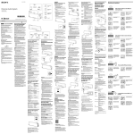
ANTENNA OMNIDIREZIONALE / MONODIREZIONALE
OMNIDIRECTIONAL/UNIDIRECTIONAL ANTENNA
ANTENNE OMNIDIRECTIONNELLE / UNIDIRECTIONNELLE
OMNIREKTIONALE/ MONODIREKTIONALE ANTENNE
ANTENA OMNIDIRECCIONAL / MONODIRECCIONAL
OMNIDIRECTIONELE/MONODIRECTIONELE ANTENNE
Attenzione! Leggere attentamente le “Avvertenze” all’interno! Caution! Read “Warnings” inside carefully! Attention! Veuillez lire attentivement les Avertissements qui se trouvent à l’intérieur! Achtung! Bitte lesen Sie
aufmerksam die „Hinweise“ im Inneren! ¡Atención¡ Leer atentamente las “Advertencias” en el interior! Let op! Lees de “Waarschuwingen” aan de binnenkant zorgvuldig!
2-
PASSY
D811682 00100_01
B
ENGLISH
50 mm
*
2
1
3
mm
*Non in dotazione /
Not supplied /
Ne sont pas fournis /
Nicht im lieferumfang /
No asignadas en el equipamiento base/
Niet meegeleverd.
C
Ø5
*
D1
FRANÇAIS
M4
5
4
R1
Ø4
6
R2
Ø4
D1
R1
R2
V1
4
V1
D
OMNIDIREZIONALE, OMNIDIRECTIONAL, OMNIDIRECTIONNELLE
OMNIDIREKTIONAL, OMNIDIRECCIONAL, OMNIDIRECTIONEEL
MONODIREZIONALE, UNIDIRECTIONAL, UNIDIRECTIONNELLE,
MONODIREKTIONAL, MONODIRECCIONAL, MONODIRECTIONEEL
DEUTSCH
10
Lb= min.1m, max10m
Lb=mini 1m, maxi 10m
Lb= mín.1m, máx. 10m
Lm= min.1m, max.20m
Lm=mini 1m, maxi 20m
Lm= mín.1m, máx. 20m
7m
Lb
ESPAÑOL
POWER SIGNAL
LED 3
..
(2x0,5 mm2)
14/28 Volt
~
PASSY -
3
NEDERLANDS
~
2-3m
LED 4
7m
Lm
2-4m
(2x0,5 mm2)
14/28 Volt
Lb
POWER SIGNAL
SW2
SW1
LED 2
LED 1
SW2
SW1
LED 2
LED 1
..
LED 3
7m
D811682 00100_01
A
mm
130 mm
4
15
ITALIANO
INSTALLAZIONE VELOCE-QUICK INSTALLATION-INSTALLATION RAPIDE
SCHNELLINSTALLATION-INSTALACIÓN RÁPIDA - SNELLE INSTALLATIE
D811682 00100_01
LEGENDA - KEY - LÉGENDE - LEGENDE - LEYENDA - LEGENDA
Fisso
Steadily lit
Fixe
Ununterbrochen an
Fijo
Continu
Spento
Unlit
Eteint
Aus
Apagado
Uitgeschakeld
lampeggio bassa frequenza
Low speed flashing
Clignotement basse fréquence
Langsam blinkend
Parpadeo baja frecuencia
Knipperen met lage frequentie
Lampeggio alta frequenza
High speed flashing
Clignotement haute fréquence
Schnell blinkend
Parpadeo alta frecuencia
Knipperen met hoge frequentie
La pressione del tasto sul TRANSPONDER. trasmette: / When the key on the TRANSPONDER is pressed, it transmits:
En appuyant sur la touche du TRANSPONDEUR on transmet: / Beim Drücken der Taste am TRANSPONDER wird gesendet:
La presión de la tecla en el TRANSPONDER transmite: / Met een druk op de toets op de TRANSPONDER wordt uitgezonden:
-sul canale dell’illuminatore solo entro il raggio d’azione dell’illuminatore
-on the illuminator's channel within the range of the illuminator only
-sur le canal de l’éclaireur uniquement dans le rayon d’action de l’éclaireur
-auf dem Kanal der Beleuchtungsvorrichtung nur innerhalb ihres Wirkungsbereiches
-en el canal del iluminador sólo dentro del radio de acción del iluminador
-op het kanaal van de belichter, alleen binnen de actieradius van de belichter
CH1-2-3-4
-su canale CH1 fuori dal raggio d’azione dell’illuminatore
-on channel CH1 out of range of the illuminator
-sur le canal de l’éclaireur uniquement dans le rayon d’action de l’éclaireur
-auf dem Kanal CH1 außerhalb des Wirkungsbereiches der Beleuchtungsvorrichtung
- en el canal CH1 fuera del radio de acción del iluminador
-op het kanaal CH1, buiten de actieradius van de belichter
CH1
E
MEMORIZZAZIONE DEI TRANSPONDER SU RICEVENTE CON ILLUMINATORE IMPOSTATO SU CANALE 1 (IMPOSTAZIONE DI FABBRICA)
MEMORIZING TRANSPONDERS ON RECEIVER WITH ILLUMINATOR SET ON CHANNEL 1 (FACTORY SETTING)
MÉMORISATION DES TRANSPONDEURS SUR LE RÉCEPTEUR AVEC ÉCLAIREUR CONFIGURÉ SUR LE CANAL 1 (CONFIGURATION D’USINE)
ABSPEICHERUNG DER TRANSPONDER IM EMPFÄNGER MIT AUF KANAL 1 EINSTELLTER BELEUCHTUNGSVORRICHTUNG (WERKSEINSTELLUNG)
MEMORIZACIÓN DE LOS TRANSPONDER EN RECEPTOR CON ILUMINADOR CONFIGURADO EN CANAL 1 (CONFIGURACIÓN DE FÁBRICA)
GEHEUGENOPSLAG VAN DE TRANSPONDERS OP ONTVANGER MET BELICHTER INGESTELD OP KANAAL 1 (FABRIEKSINSTELLING)
1
Centrali con display / Control units with display
Centrales avec afficheur / Steuergeräte mit Display
Centrales con pantalla / Centrales met display
4
5
Timeout/Délai/Interrupción 10 s.
5s
Riceventi/Receivers/Récepteurs/Empfänger/Receptores/Ontvangers
Attenersi alle istruzioni della
ricevente/centrale utilzzata!
Comply with the instructions relating
to the receiver/control unit used!
1s
Se conformer aux instructions du
récepteur ou de la centrale utilisée!
2
CH1=OK
Beachten Sie die Anweisungen des
verwendeten Empfängers/Steuergeräts!
Seguir las instrucciones del
receptor/central utilizada!
U aan de gebruiksaanwijzingvan de
gebruikte ontvanger/centrale houden!
1
CH
3
Timeout/Délai
Interrupción 1 min.
4-
PASSY
6A
6B
SW1
LED1 LED2
LED3
1
LED1 LED2
SW1
= CH1
2x
= CH2
3x
= CH3
4x
= CH4
2
SW1
SW1
SW2
1x
SW1
SW1
4
LED1 LED2
LED3
LED1 LED2
3
SW1
SW1
SW2
SW2
MEMORIZZAZIONE DEI TRANSPONDER SU RICEVENTE CON ILLUMINATORE IMPOSTATO SU CANALE 2-3-4
MEMORIZING TRANSPONDERS ON RECEIVER WITH ILLUMINATOR SET ON CHANNELS 2-3-4
MÉMORISATION DES TRANSPONDEURS SUR LE RÉCEPTEUR AVEC ÉCLAIREUR CONFIGURÉ SUR LES CANAUX 2-3-4
ABSPEICHERUNG DER TRANSPONDER IM EMPFÄNGER MIT AUF DIE KANÄLE 2-3-4 EINGESTELLTER BELEUCHTUNGSVORRICHTUNG
MEMORIZACIÓN DE LOS TRANSPONDER EN RECEPTOR CON ILUMINADOR CONFIGURADO EN CANAL 2-3-4
GEHEUGENOPSLAG VAN DE TRANSPONDERS OP ONTVANGER MET BELICHTER INGESTELD OP KANAlen 2-3-4
10
CH2
...0s ...
CH3
G
s
1
CH4
D811682 00100_01
F
IMPOSTAZIONE DEI CANALI SULL’ILLUMINATORE, SETTING CHANNELS ON THE ILLUMINATOR,
CONFIGURATION DES CANAUX SUR L'ÉCLAIREUR, EINSTELLUNG DER KANÄLE AAN DER BELEUCHTUNGSVORRICHTUNG,
CONFIGURACIÓN DE LOS CANALES EN EL ILUMINADOR, INSTELLING VAN DE KANALEN OP DE BELICHTER
10 s
Centrali con display / Control units with display / Centrales avec afficheur
Steuergeräte mit Display / Centrales con pantalla / Centrales met display
2
3
...5s ...
...10s
4
TIMEOUT 5min.
5
6
Timeout/Délai/Interrupción :10 s.
Riceventi / Receivers / Récepteurs/Empfänger / Receptores /Ontvangers
Attenersi alle istruzioni della ricevente/centrale utilzzata!
Comply with the instructions relating to the receiver/control unit used!
Se conformer aux instructions du récepteur ou de la centrale utilisée!
Beachten Sie die Anweisungen des verwendeten Empfängers/Steuergeräts!
Seguir las instrucciones del receptor/central utilizada!
U aan de gebruiksaanwijzing van de gebruikte ontvanger/centrale houden!
CH 2,3,4=OK
1s
PASSY -
5
2
LED1 LED2
LED3
1
LED 3
3
x 10 sec.
SW1 SW2
SW2
SW1
LED 2
LED 1
CH3
H1
CH1
CH2
CH3
CH4
LED1 LED2
LED3
SW1 SW2
OK
KO
KO
KO
LED1 LED2
Vedi nota nel testo.
See note in text.
Cf. remarque dans le texte.
Siehe Anmerkung im Text.
Véase nota en el texto.
Zie opmerking in de tekst.
PROCEDURA DI ASSOCIAZIONE MANUALE DELL’ILLUMINATORE PER OGNI SINGOLO TRANSPONDER
PROCEDURE FOR ASSOCIATING THE ILLUMINATOR MANUALLY FOR EACH INDIVIDUAL TRANSPONDER
PROCÉDURE D’ASSOCIATION MANUELLE DE L’ÉCLAIREUR POUR CHAQUE TRANSPONDEUR
VERFAHRENS FÜR DIE MANUELLE ZUORDNUNG DER BELEUCHTUNGSVORRICHTUNG FÜR JEDEN EINZELNEN TRANSPONDER
PROCEDIMIENTO DE ASOCIACIÓN MANUAL DEL ILUMINADOR PARA CADA UNO DE LOS TRANSPONDER
HANDMATIGE KOPPELINGSPROCEDURE VAN DE BELICHTER VOOR IEDERE AFZONDERLIJKE TRANSPONDER
LED1 LED2
x 1 sec.
3
s
Vedi nota nel testo.
See note in text.
Cf. remarque dans le texte.
Siehe Anmerkung im Text.
Véase nota en el texto.
Zie opmerking in de tekst.
...0s ...
...5s ...
...10s
10 s
TIMEOUT 5min.
4
5
CH1
CH2
CH3
CH4
OK
KO
KO
KO
USCITA DALLA PROCEDURA DI ASSOCIAZIONE MANUALE DELL’ILLUMINATORE PER OGNI SINGOLO TRANSPONDER
HOW TO EXIT THE PROCEDURE FOR ASSOCIATING THE ILLUMINATOR MANUALLY FOR EACH INDIVIDUAL TRANSPONDER
SORTIE DE LA PROCÉDURE D’ASSOCIATION MANUELLE DE L’ÉCLAIREUR POUR CHAQUE TRANSPONDEUR
VERLASSEN DES VERFAHRENS FÜR DIE MANUELLE ZUORDNUNG DER BELEUCHTUNGSVORRICHTUNG FÜR JEDEN EINZELNEN TRANSPONDER
SALIDA DEL PROCEDIMIENTO DE ASOCIACIÓN MANUAL DEL ILUMINADOR PARA CADA UNO DE LOS TRANSPONDER
HANDMATIGE KOPPELINGSPROCEDURE VAN DE BELICHTER VOOR IEDERE AFZONDERLIJKE TRANSPONDER VERLATEN
LED1 LED2
LED3
LED1 LED2
SW1 SW2
SW1 SW2
SW1 SW2
PASSY
LED3
LED1 LED2
LED3
6-
x 1 sec.
2
SW1 SW2
10
LED3
LED 3
SW1 SW2
SW1 SW2
SW2
SW1
LED 2
LED 1
CH3
LED1 LED2
LED3
LED1 LED2
LED3
1
H2
D811682 00100_01
PROCEDURA DI ASSOCIAZIONE AUTOMATICA DELL’ILLUMINATORE CON CANALE IMPOSTATO AL TRANSPONDER
PROCEDURE FOR ASSOCIATING THE ILLUMINATOR AUTOMATICALLY WITH THE CHANNEL SET ON THE TRANSPONDER
PROCÉDURE D’ASSOCIATION AUTOMATIQUE DE L’ÉCLAIREUR AVEC LE CANAL CONFIGURÉ SUR LE TRANSPONDEUR
VERFAHREN FÜR DIE AUTOMATISCHE ZUORDNUNG DER BELEUCHTUNGSVORRICHTUNG ZU DEM AUF DEM TRANSPONDER EINGESTELLTEN KANAL
PROCEDIMIENTO DE ASOCIACIÓN AUTOMÁTICA DEL ILUMINADOR CON CANAL CONFIGURADO AL TRANSPONDER
PROCEDURE VOOR AUTOMATISCHE KOPPELING VAN DE BELICHTER MET OP DE TRANSPONDER INGESTELD KANAAL
SW1 SW2
SW1 SW2
x10s
LED4
LED4
LED1 LED2
LED3
x5
3
LED1 LED2
2
LED3
LED1 LED2
LED3
1
x5
x5
4
x5
D811682 00100_01
I
PROCEDURA DI CANCELLAZIONE TRANSPONDER / TRANSPONDER DELETION PROCEDURE
PROCÉDURE DE SUPPRESSION DES TRANSPONDEURS / VERFAHREN FÜR DAS LÖSCHEN DER TRANSPONDER
PROCEDIMIENTO DE BORRADO TRANSPONDER / PROCEDURE VOOR HET WISSEN VAN TRANSPONDERS
5
SW1 SW2
LED4
COLLEGAMENTO GESTIONE PROGRAMMATORE PALMARE UNIVERSALE/ UNIVERSAL HANDHELD PROGRAMMER MANAGEMENT CONNECTION
CONNEXION GESTION DU PROGRAMMATEUR PALMAIRE UNIVERSLE / ANSCHLUSS UNIVERSAL-HANDPROGRAMMIERGERÄT
CONEXIÓN GESTIÓN PROGRAMADOR PORTÁTIL UNIVERSAL / AANSLUITING BEHEER UNIVERSELE PROGRAMMEERBARE PALMTOP
J
OK
OK
KO
PASSY -
7
LED1 LED2
LED3
3
1
SW1 SW2
x10s
LED4
LED1 LED2
LED3
2
SW1 SW2
LED4
TIMEOUT 5 min.
USCITA DALLA FUNZIONE TRACER, HOW TO EXIT THE TRACER FUNCTION, SORTIE DE LA FONCTION TRACER
VERLASSEN DER FUNKTION TRACER, SALIDA DE LA FUNCIÓN TRACER, TRACER-FUNCTIE VERLATEN
LED1 LED2
LED3
1
SW1 SW2
LED4
LED1 LED2
LED3
2
SW1 SW2
x10s
LED4
LED1 LED2
LED3
SW1 SW2
LED4
8-
PASSY
K
3
D811682 00100_01
ATTIVAZIONE DELLA FUNZIONE TRACER, ACTIVATING THE TRACER FUNCTION
ACTIVATION DE LA FONCTION TRACEUR, AKTIVIERUNG DER FUNKTION TRACER
ACTIVACIÓN DE LA FUNCIÓN TRACER, ACTIVERING VAN DE FUNCTIE TRACER
1
5s
2
3
5s
4
xxxx.x.01
5
6
xxxx.x.100
7
+/-
+/-
OK
aut.
TIMEOUT 60s
Aggiungi
add
adjouter
zufugen
anadir
- +
man.
xxxx.x.01
- +
FINE
Blocco
group
bloc
block
bloque
out-ausi
salida
1 . .4
primo trasm.
first tras.
premier em.
erster send.
primer trans.
OK
tasto nascosto
hidden button
touche cachee
verst.taste
tecla escond.
tasto desid.
desired button
touche desiree
gevue taste
tecla deseada
tasto nascosto
hidden button
touche cachee
verst.taste
tecla escond.
ultimo trasm.
last tras.
dernier em.
letzter send.
- +
tutte-all-tous
todas-alle
xxxx.x.100
ultimo trasm.
last tras.
dernier em.
letzter send.
tasto desid.
desired button
touche desiree
gevue taste
tecla deseada
tasto nascosto
hidden button
touche cachee
verst.taste
tecla escond.
OK
0001
OK
0100
PROGRAMMAZIONE A BLOCCHI SU RTD ILLUMINATORE CANALI 2-3-4 / BLOCK PROGRAMMING ON ILLUMINATOR RTD CHANNELS 2-3-4
PROGRAMMATION PAR BLOCS SUR RTD ÉCLAIREUR CANAUX 2-3-4/BLOCK-PROGRAMMIERUNG AN RTD BELEUCHTUNGSVORRICHTUNG KANÄLE 2-3-4
PROGRAMACIÓN EN BLOQUES EN RTD ILUMINADOR CANALES 2-3-4/BLOKKENPROGRAMMERING OP RTD BELICHTER KANALEN 2-3-4
10
10
s
s
1
2
...0s ...
3
...5s ...
4
5
...10s
...0s ...
TIMEOUT 5min.
10 s
6
7
...5s ...
...10s
TIMEOUT 5min.
10 s
xxxx.x.01
8
xxxx.x.100
9
+/-
+/FINE
Aggiungi
add
adjouter
zufugen
anadir
OK
aut.
- +
man.
TIMEOUT 5m
D811682 00100_01
L
PROGRAMMAZIONE A BLOCCHI SU RTD ILLUMINATORE CANALE 1 / BLOCK PROGRAMMING ON ILLUMINATOR RTD CHANNEL 1
PROGRAMMATION PAR BLOCS SUR RTD ÉCLAIREUR CANAL 1 / BLOCK-PROGRAMMIERUNG AN RTD BELEUCHTUNGSVORRICHTUNG KANAL 1
PROGRAMACIÓN EN BLOQUES EN RTD ILUMINADOR CANAL 1 / BLOKKENPROGRAMMERING OP RTD BELICHTER KANAAL 1
xxxx.x.01
- +
Blocco
group
bloc
block
bloque
out-ausi
salida
1 . .4
OK
primo trasm.
first tras.
premier em.
erster send.
primer trans.
tasto nascosto
hidden button
touche cachee
verst.taste
tecla escond.
tasto desid.
desired button
touche desiree
gevue taste
tecla deseada
ultimo trasm.
last tras.
dernier em.
letzter send.
tasto nascosto
hidden button
touche cachee
verst.taste
tecla escond.
- +
tutte-all-tous
todas-alle
xxxx.x.100
ultimo trasm.
last tras.
dernier em.
letzter send.
tasto nascosto
hidden button
touche cachee
verst.taste
tecla escond.
tasto desid.
desired button
touche desiree
gevue taste
tecla deseada
OK
0001
OK
0100
PASSY -
9
WARNING! Important safety instructions. Carefully read and comply with the
Warnings booklet and Instruction booklet that come with the product as incorrect
installation can cause injury to people and animals and damage to property. They
contain important information regarding safety, installation, use and maintenance.
Keep hold of instructions so that you can attach them to the technical file and
keep them handy for future reference.
1) GENERAL SAFETY
WARNING! An incorrect installation or improper use of the product can
cause damage to persons, animals or things.
- The units making up the machine and its installation must meet the requirements
of the following European Directives: 99/05/EEC and later amendments. For all
countries outside the EEC, it is advisable to comply with the above-mentioned
standards, in addition to any national standards in force, to achieve a good
level of safety.
- The Firm disclaims all responsibility resulting from improper use or any use
other than that for which the product has been designed, as indicated herein, as well as for failure to apply Good Practice in the construction of entry
systems (doors, gates, etc.) and for deformation that could occur during use.
- Make sure the stated temperature range is compatible with the site in which
the automated system is due to be installed.
- Do not install the product in an explosive atmosphere.
- Disconnect the electricity supply before performing any work on the system.
Also disconnect buffer batteries, if any are connected.
- Apply all safety devices (photocells, safety edges, etc.) required to keep the
area free of crushing, dragging and shearing hazards.
- Only use original spare parts for any maintenance or repair work. The Firm
disclaims all responsibility for the correct operation and safety of the automated system if parts from other manufacturers are used.
- Do not make any modifications to the automated system’s components unless explicitly authorized by the Firm.
- Dispose of packaging materials (plastic, cardboard, polystyrene, etc.) in accordance with the provisions of the laws in force. Keep nylon bags and polystyrene out of reach of children.
- Anything which is not expressly provided for in the present instructions, is not
allowed.
- The maximum permissible length for the DATA LINE is 20 metres.
- Do not run cables on the board through the area between the connectors and
keys as this results in malfunctioning.
- Make sure that cable polarity is as indicated on the board.
- Make sure that your motor vehicle is not fitted with shielded glass, otherwise
you will need to position the TRANSPONDER according to the instructions in
the car’s handbook, which should identify a suitable point for installation.
WARNING: extremely low safety voltage cables must be phisically
separated from low voltage cables.
Access to the electrical compartment or to limit switches must be allowed
to skilled personnel only.
Compliance with current safety rules with regard to people, animals and property
must be assured at all times and, more specifically, measures must be taken to avoid
risks of injury due to crushing, in the area where the pinion and rack mesh, and
any other mechanical hazards. All critical points must be protected by safety
devices in accordance with the provisions of the regulations in force.
SCRAPPING
Materials must be disposed of in conformity with the current regulations.
In case of scrapping, the automation devices do not entail any particular risks
or danger. In case of recovered materials, these should be sorted out by type
(electrical components, copper, aluminium, plastic etc.).
DISMANTLING
When the automation system is disassembled to be reassembled on another
site, proceed as follows:
- Disconnect the power supply and the entire electrical installation.
- Remove the actuator from its fixing base.
- Disassemble all the installation components.
- In the case where some of the components cannot be removed or are damaged, they must be replaced.
Correct controller operation is only ensured when the data contained in the
present manual are observed. The Company is not to be held responsible
for any damage resulting from failure to observe the installation standards
and the instructions contained in the present manual.
The descriptions and illustrations contained in the present manual are
not binding. The Company reserves the right to make any alterations
deemed appropriate for the technical, manufacturing and commercial
improvement of the product, while leaving the essential product features
unchanged, at any time and without undertaking to update the present
publication.
PASSY
D811682 00100_01
GENERAL WARNINGS
D811682 00100_01
ITALIANO
INSTALLATION MANUAL
1) FOREWORD
The PASSY system comprises an illuminator that “activates” the TRANSPONDERS,
which in turn transmit a code on 433.92 MHz.
2) TECHNICAL SPECIFICATIONS
Power supply
14-28 V
Current demand
TYP 3W MAX 6W
; 14-28 V~ 50-60 Hz
Band
2400-2483 MHz
Power
Max. average 100mW EIRP
IP rating
IP55
Operating temperature
range
Illuminator: -20°C +70°C
Transponder: -10°C + 60°C
ENGLISH
Typical consumption:
Supply voltage
Consumption [mA]
14
180
14 ~
210
24
90
24 ~
140
The illuminator can activate just 1 channel. When working with a number of
receivers, set a different channel on each illuminator: 1 for each receiver.
3) DIMENSIONS FIG.A
4) INSTALLATION FIG.B-C
- Knocking out holes in boxes Fig. B
- Wall mounting of box Fig. C
5) UNIDIRECTIONAL AND OMNIDIRECTIONAL ANTENNA FIG. D
Make sure you keep the area around the antenna completely clear. Any obstacle
between the antenna and TRANSPONDER can reduce the system’s performance.
Even plants, especially when watered, can interfere with operation.
POWER SIGNAL (Fig.D): adjusts the power of the signal emitted by the antenna.
6) MEMORIZING TRANSPONDERS ON RECEIVER WITH ILLUMINATOR SET ON
CHANNEL 1 (FACTORY SETTING) FIG.E
WARNING! It is advisable to:
- register TRANSPONDERS on the 2nd radio channel and activate the OPEN
input, where available, with the receiver’s 2nd radio channel terminal.
Or:
- enable the following logic: TCA, block pulses opening, block pulses TCA,
and 3-step logic where available.
Pressing the TRANSPONDER’s key causes the code to be transmitted on channel 1.
The illuminator is factory set by default to channel 1.
7) SETTING CHANNELS ON THE ILLUMINATOR FIG.F
Set the channel from 1 to 4 on the illuminator
Each illuminator transmits on one channel only.
8) MEMORIZING TRANSPONDERS ON RECEIVER WITH ILLUMINATOR SET ON
CHANNELS 2-3-4 FIG.G
When the key on the TRANSPONDER is pressed, it transmits:
- on the illuminator’s channel within the range of the illuminator only.
- on channel CH1 if out of range of the illuminator.
9) PROCEDURE FOR ASSOCIATING THE ILLUMINATOR AUTOMATICALLY WITH
THE CHANNEL SET ON THE TRANSPONDER FIG.H1
The TRANSPONDER is activated in the area by registered illuminators only. Up to 50
illuminators can be registered for each TRANSPONDER.
This operation serves to associate the illuminator with TRANSPONDERS that
are within range of the illuminator. Consequently, you must make sure
that the illuminator’s range is free of any TRANSPONDERS that you do not
want to register the illuminator on.
PROCEDURE FOR ASSOCIATING THE ILLUMINATOR MANUALLY FOR EACH
INDIVIDUAL TRANSPONDER FIG.H2
This operation consists in associating the individual illuminators on the
TRANSPONDER, which will subsequently only transmit the signal if it is
within range of a previously associated illuminator.
10) TRANSPONDER DELETION PROCEDURE FIG. I
All associations of all illuminators registered in the transponders can be
deleted via this procedure.
Consequently, you must make sure that the illuminator’s range is
free of any TRANSPONDERS with which you do not want to delete the
illuminators’ association.
11) UNIVERSAL HANDHELD PROGRAMMER MANAGEMENT CONNECTION FIG. J
Make sure that the universal handheld programmer version is compatible with
the TRANSPONDERS.
12) ACTIVATING THE TRACER FUNCTION FIG.K
This function can be used to trace the range of the illuminator through the flashing
of the transponder’s LED. When a transponder is within range of the illuminator
on which the TRACER function has been activated, the LED flashes, but no RADIO
code is transmitted.
13) FIG. L:
BLOCK PROGRAMMING ON ILLUMINATOR RTD CHANNEL 1
BLOCK PROGRAMMING ON ILLUMINATOR RTD CHANNELS 2-3-4
PASSY -
13


