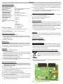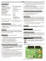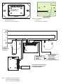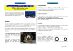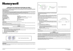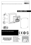
1
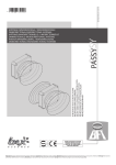
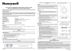
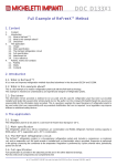
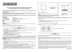
FC410RIM
MODULO RELÈ
RELAY INTERFACE MODULE
FC AUSGANGSELEMENT, NICHT ÜBERWACHT
LEAFLET 120.415.969
ISTISBL3FC410RIM 0.3 260809
FireClass
DEUTSCH
Best.-Nr. 568.800.703
ANWENDUNG
Das FC Ausgangselement FC410RIM stellt einen potentialfreien
Relaisausgang (Umschalter 24 V DC, 2 A) zur Verfügung.
Es kann mit FireClass 500 Console auf zwei Betriebsarten eingestellt
werden:
Ø Türsteuerung
Ø Steuerung
TECHNISCHE DATEN
System-Kompatibilität:
Adressierbares FC Brandmeldesystem
Elementtyp (Kennung):
161
Spannungsversorgung aus der
Ringleitung:
20 bis 40 V
Stromaufnahme
im Bereitschaftsbetrieb:
0,3 mA
im Alarmzustand (mit roter LED): 3 mA
Relais-Schaltleistung:
30 V/2 A
Umgebungstemperatur im Betrieb: -25 bis 70 °C
Luftfeuchte:
max.95 % (ohne Betauung)
Gehäuseabmessungen (B x H x T): 140 x 120 x 70 mm
Gewicht:
260 g
ADRESSEINSTELLUNG
Per Auslieferungszustand ist die Adresse standardmäßig auf 255 gesetzt.
Zum Einstellen der individuellen Systemadresse kann das
Handprogrammiergerät FC490ST am Programmierstecker angeschlossen
werden (siehe Abb.2).
EINBAU INS FC470CV ANCILLRY GEHÄUSE
FC470CV Gehäuse-Orberteil ist extra zu bestellen
Best.Nr: FC470CV
1) Befestigen Sie di FC410RIM an der Montageplatte von FC470CV,
benutzen Sie dafür die gelieferte vier Schrauben und Scheiben.
2) Bauen Sie den Deckel auf den doppelten Untergehäuse.
VERKABELUNG
An die Anschlussklemmen können Kabel mit Drahtquerschnitten bis zu 1,5
mm2 angeschlossen werden.
Es werden geschirmte Brandmeldekabel des Typs J-Y(ST)Y nx2x0,8
empfohlen.
ANSCHLIEßEN
1) Am FC410RIM müssen keine DIP-Schalter- oder Steckbrücken-Einstellungen
vorgenommen werden.
2) Alle Leiter müssen erdfrei sein.
3) Stellen Sie die korrekte Polung der Verkabelung sicher, bevor Sie das
FC410RIM an die Ringleitungsspannung anschließen.
4) Abbildung 4 zeigt eine typische Verkabelung des FC410RIM.
0832
BENTEL SECURITY s.r.l.
Via Gabbiano, 22 - Zona Ind. S. Scolastica
64013 Corropoli (TE) - ITALY
09
0832-CPD-1228
EN 54-18
Input/output device for fire detection and fire alarm systems
for buildings
FC410RIM
Abb. 1: FC Ausgangselement, nicht überwacht - FC410RIM
ENGLISH
TECHNICAL SPECIFICATION
6) For dry contact switching, connect the external circuit to the COM and N/O
Type Identification Value:
161
System Compatibility:
Use only with FC Fire Alarm Controllers
Environment:
Indoor Application only
o
Operating Temperature:
-25 to +70 C
o
Storage Temperature:
-40 to +80 C
Operating Humidity:
Up to 95% non-condensing
Dimensions (HxWxD):
87 x 148 x 14 mm
Mounting Requirements:
One FC backbox surface mount
Battery Requirements:
Standby Current:
0.46mA max
Alarm Current:
4.5mA max
Addressable Device Conditions:
– Normal
– Active
– Output Stuck
– Device Type Invalid
– Device No Response
Relay Contact Rating:
DC – 2A @ 24V dc
+ Note: The module must not be used to switch mains voltages
Recommended Wire Size:
or N/C terminals for normally open or normally closed operation as required.
7) Verify that relay wiring is correct for the FC410RIM before connecting to
the addressable loop circuit.
8) For connection to an HVR800 High Voltage Relay Module, refer to Installation Sheet 17A-03-HVR or 120-415-528.
INSTALLATION TO FC470CV DOUBLE GANG COVER
1) Assemble the FC410RIM to FC470CV Double Gang cover, using the
four screws and washers provided.
2) Snap on the ancillary housing PCB cover.
3) Fit cover onto FC backbox.
ADDRESS SETTINGS
The FC410RIM has a default factory set address of 255, this must be set to
the loop address of the device using the FC490ST Loop Service Tool. The
FC410RIM may be programmed with the address prior to being installed by
using the internal programming port (see Fig.2) or after being installed by
using the programming port on the front cover (see Fig.3).
+ Note: once the address has been programmed, take note of the device
location and address number, to include on site drawings.
Min. 1.5 mm2 Max. 2.5 mm2
Electromagnetic Compatibility
The FC410RIM complies with the following:
Ø product family standard EN50130-4 in respect of Conducted Disturbances, Radiated Immunity, Electrostatic Discharge, Fast Transients
and Slow High Energy;
Ø EN50081-1 for emissions.
INTRODUCTION
The FC410RIM Relay Interface Module provides one volt-free relay changeover contact on a latching relay. The relay is controlled by a command sent
from the FC fire controller via the addressable loop. The relay state (activated, deactivated or stuck) is returned to the controller.
FEATURES
FC410RIM features include the following:
Ø Addressable functionality.
The control panel sends a command to operate the relay, then reports an
activated or deactivated state back to the panel through the use of a set of
contacts dedicated to monitor the state of the relay.
Ø One volt-free dry contact relay output.
Ø Output to drive a high voltage relay HVR800.
Ø LED status indicator which is normally off. When the FC410RIM receives
a command to activate, the LED lights.
CABLING
The maximum section of the cable that can be connected at any one terminal is 2.5mm2. The section is calculated based on the characteristics of the
cable and the load.
ORDERING INFORMATION
FC410RIM: Relay Input Module:
FC470CV: Double-Gang cover
RECYCLING INFORMATION
Customers are recommended to dispose of their used equipments (panels,
detectors, sirens, and other devices) in an environmentally sound manner.
Potential methods include reuse of parts or whole products and recycling of
products, components, and/or materials.
WASTE ELECTRICAL AND ELECTRONIC EQUIPMENT (WEEE)
DIRECTIVE
In the European Union, this label indicates that this product
should NOT be disposed of with household waste. It should be
deposited at an appropriate facility to enable recovery and recycling.
The manufacturer reserves the right to change the technical specifications
of this product without prior notice.
WIRING & INSTALLATION NOTES
! CAUTION:THE O+ AND O- TERMINALS MUST NOT BE USED.FOR
CONNECTING THE FC410RIM TO AN HVR800, SEE PUBLICATION
17A-03-HVR OR 120-415-528.
The following notes apply:
1) There are no user-required settings (switches, headers) on the
FC410RIM. All wiring must be free of earths.
2) All wiring must conform to the applicable standards.
3) See Figure 4 for FC410RIM Simplified Wiring Diagram.
4) For 24V dc powered applications, only use a regulated supply suitable
for fire protective signalling service.
5) For powered circuit operation, route the positive conductor through the
FC410RIM to the external device, while connecting the common (neutral) conductor to the external circuit.
FIG. 1
FC410RIM Relay Interface Module
ITALIANO
SPECIFICHE TECNICHE
Valore Identificativo:
Compatibilità:
Caratteristiche ambientali:
Temperatura di funzionamento:
Temperatura di stoccaggio:
Umidità relativa:
Dimensioni (HxLxP):
Requisiti di montaggio:
Corrente assorbita:
Corrente a riposo:
Corrente in allarme:
Stati del dispositivo indirizzabile:
Caratteristiche del contatto relè:
6) Per la commutazione dello scambio libero collegare il circuito esterno ai
161
usare solo con Centrali serie FC
Solo per applicazioni interne
o
da -25 a +70 C
o
da -40 a +80 C
fino a 95% (senza condensa)
87 x 148 x 14 mm
A parete su scatola FC
Min. 1,5 mm2 Max. 2,5 mm2
Compatibilità Elettromagnetica
Il modulo FC410RIM è conforme a quanto segue:
Ø famiglia di prodotto standard EN50130-4 rispetto alle Perturbazioni
Dirette, Immunità Irradiata, Scarica Elettrostatica, Transitorie Rapide e
Alta Energia Lenta;
Ø EN50081-1 per le emissioni.
INTRODUZIONE
Il modulo relè FC410RIM fornisce uno scambio libero da tensione su un aggancio del relè. Il relè è controllato tramite un comando inviato dalla Centrale FireClass attraverso il loop indirizzabile. Lo stato del relè (attivo, non
attivo o collegato) è inviato alla Centrale.
CARATTERISTICHE
Il modulo FC410RIM include le seguenti caratteristiche:
Ø Funzione Indirizzabile
La Centrale trasmette un comando operativo al relè, il quale segnala lo
stato di attivazione o disattivazione alla Centrale che utilizza un insieme
di contatti dedicati al controllo dello stato del relè.
Ø Uscita relè con uno scambio libero da tensione.
Ø Uscita per il controllo di un relè alta tensione HVR800.
Ø Il LED che indica lo stato è normalmente in OFF .
Quando il modulo FC410RIM riceve un comando di attivazione, il LED si illumina.
NOTE PER IL COLLEGAMENTO E L'INSTALLAZIONE
! ATTENZIONE: I TERMINALI
INSTALLAZIONE NEL COPERCHIO FC470CV DOUBLE-GANG
1) Assemblare l'FC410RIM con il coperchio per scatole americane Double-Gang FC470CV,usando le quattro viti e le rondelle fornite.
0,46 mA
4,5 mA
– Normale
– Attivo
– Uscita bloccata
– Dispositivo non valido
– Dispositivo non risponde
CC - 2A @ 24 Vcc
+ Nota: Il modulo non deve essere usato per commutare la tensione di rete
Sezione cavi consigliata:
morsetti COM e N/O o N/C per il funzionamento normalmente aperto o
normalmente chiuso come necessario.
7) Verificare la corretta polarità dei collegamenti prima di connettere il modulo FC410RIM al circuito loop indirizzabile.
8) Per il collegamento ad un modulo relè ad alta tensione HVR800, consultare il documento d'installazione 17A-03-HVR oppure 120-415-528.
O+ E O- NON DEVONO ESSERE
UTILIZZATI. PER IL COLLEGAMENTO DEL MODULO FC410RIM AL
RELÈ ALTA TENSIONE HVR800, CONSULTARE IL DOCUMENTO
17A-03-HVR OPPURE 120-415-528.
Osservare le seguenti note:
1) Sul modulo FC410RIM non ci sono regolazioni da effettuare (interruttori
o altro). Tutti i conduttori devono essere senza terra.
2) Tutti i collegamenti devono essere conformi alle norme applicabili.
3) Vedere figura 4 per lo schema di collegamento del modulo FC410RIM.
4) Per l'alimentazione delle applicazioni 24 Vcc usare soltanto un alimentatore
supplementare per la protezione del servizio di segnalazione incendio.
5) Per il funzionamento alimentato del circuito, portare il conduttore positivo del modulo FC410RIM al dispositivo esterno ed il conduttore comune
(neutro) al circuito esterno.
2) Bloccare il PCB sull'alloggiamento del coperchio.
3) Fissare il coperchio sulla scatola FC.
PROGRAMMAZIONE
L'indirizzo di fabbrica del FC410RIM è 255, questo deve essere impostato
all'indirizzo di loop del dispositivo tramite lo strumento per la programmazione dei dispositivi indirizzabili FC490ST. L'indirizzo del FC410RIM può essere programmato prima dell'installazione usando la porta di programmazione
interna (vedere Fig.2) o dopo l'installazione usando la porta di programmazione sul coperchio (vedere Fig.3).
+ Nota: una volta programmato l'indirizzo, annotare la posizione del dispositivo e l'indirizzo, per segnarlo sul progetto dell'impianto.
COLLEGAMENTI
La sezione massima del cavo collegabile ad ogni morsetto è di 2,5 mm2. La
sezione và calcolata in base alle caratteristiche del cavo e del carico.
INFORMAZIONI PER L'ORDINE
FC410RIM: Modulo relè
FC470CV: Coperchio per scatola americana Double-Gang
INFORMAZIONI SUL RICICLAGGIO
Si consiglia ai clienti di smaltire i dispositivi usati (centrali, rilevatori, sirene,
accessori elettronici, ecc.) nel rispetto dell'ambiente. Metodi potenziali comprendono il riutilizzo di parti o di prodotti interi e il riciclaggio di prodotti, componenti e/o materiali.
DIRETTIVA RIFIUTI DI APPARECCHIATURE ELETTRICHE ED
ELETTRONICHE (RAEE - WEEE)
Nell'Unione Europea, questa etichetta indica che questo prodotto NON deve essere smaltito insieme ai rifiuti domestici.
Deve essere depositato in un impianto adeguato che sia in
grado di eseguire operazioni di recupero e riciclaggio.
Il costruttore si riserva il diritto di modificare le specifiche tecniche di questo
prodotto senza preavviso.
FIG. 1
FC410RIM Modulo relè
TB3
TB2
TB1
L+ L- L+ L- O+ O-
N/O
C
N/C
PORTA DI PROGRAMMAZIONE
PROGRAMMING PORT
PROGRAMMIERANSCHLUSS
PORTA DI PROGRAMMAZIONE
ADDRESS SETTING PORT
PROGRAMMIERANSCHLUSS
FIG. 2 FC410RIM fissata al coperchio
FC410RIM fitted to cover
FC410RIM ins Gehäuse eingebaut
FIG. 3 FC410RIM Placca
Facia Plate
Kurzschlussisolator Vorderseite
L1
RIGHT
L1
L1
LEFT
L1
L+ L- L+ L- O+ O-
CENTRALE FC
FC CONTROLLER
FC ZENTRALE
C
N/C
P1
P1
L+ L- L+ L- O+ ON/O
C
N/C
FIG. 4
N/O
FC410RIM Schema di collegamento
FC410RIM Simplified Wiring Diagram
Typische Verdrahtung des FC410RIM
ALIMENTATORE
POWER SUPPLY UNIT
ENERGIEVERSORGUNG
CIRCUITO ELETTRONICO SWITCHING
ELECTRONIC SWITCHING CIRCUIT
SCHALTBARE BAUGRUPPE
DISPOSITIVO ESTERNO/
CIRCUITO COMMUTABILE
EXTERNAL DEVICE/
SWITCHABLE CIRCUIT
EIN-UND AUSSCHALTBARER VERBRAUCHER