1
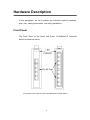
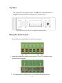
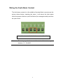
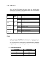
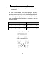
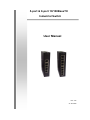
5-port & 8-port 10/100BaseTX Industrial Switch User Manual Rev.1.06 21-Jan-2008 FCC Warning This Equipment has been tested and found to comply with the limits for a Class A digital device, pursuant to Part 15 of the FCC rules. These limits are designed to provide reasonable protection against harmful interference in a residential installation. This equipment generates, uses, and can radiate radio frequency energy. It may cause harmful interference to radio communications if the equipment is not installed and used in accordance with the instructions. However, there is no guarantee that interference will not occur in a particular installation. If this equipment does cause harmful interference to radio or television reception, which can be determined by turning the equipment off and on, the user is encouraged to try to correct the interference by one or more of the following measures: Reorient or relocate the receiving antenna. Increase the separation between the equipment and receiver. Connect the equipment into an outlet on a circuit different from that to which the receiver is connected. Consult the dealer or an experienced radio/TV technician for help. CE Mark Warning This is a class A product. In a domestic environment this product may cause radio interference in which case the user may be required to take adequate measures. Content FCC Warning....................................................... i CE Mark Warning ................................................ i Overview............................................................. 1 Introduction .............................................................. 1 Features ................................................................... 3 Packing List.............................................................. 4 Safety Precaution..................................................... 4 Hardware Description ......................................... 5 Front Panel............................................................... 5 Top View .................................................................. 6 Wiring the Power Inputs ........................................... 6 Wiring the Fault Alarm Contact ................................ 7 LED Indicators.......................................................... 8 Ports......................................................................... 8 Cabling ................................................................... 10 Mounting Installation ........................................ 11 DIN-Rail Mounting.................................................. 11 Wall Mount Plate Mounting .................................... 13 Hardware Installation........................................ 14 Installation Steps.................................................... 14 Troubleshooting................................................ 16 Technical Specification..................................... 17 Overview Introduction This user manual is suitable for the products as follows: • 5-port 10/100TX Unmanaged Industrial Switch • 8-port 10/100TX Unmanaged Industrial Switch The unmanaged industrial switch is a cost-effective solution and meets the high reliability requirements demanded by industrial applications. High-Speed Transmissions The Industrial switch includes a switch controller that can automatically sense transmission speeds (10/100 Mbps). The RJ-45 interface can also be auto-detected, so MDI or MDI-X is automatically selected and a crossover cable is not required. All Ethernet ports have memory buffers that support the store-and-forward mechanism. This assures that data is properly transmitted. Dual Power Input To reduce the risk of power failure, the Industrial switch provides +12 ~ +48 VDC dual power inputs. If there is power failure, Industrial switch will automatically switch to the secondary power input. Flexible Mounting The industrial switch is extremely compact and can be mounted on a DIN-rail or a panel, so it is suitable for any space-constrained environment. Advanced Protection The power line of Industrial switch supports up to 3,000 VDC EFT protection, which secure equipment against unregulated voltage and make systems safer and more reliable. Meanwhile, 6,000 VDC ESD protections for Ethernet ports make Industrial switch more suitable for harsh environments. 1 Wide Operating Temperature The operating temperature of the Industrial switch is between -40 ~ 75oC (wide operating temperature model) or -10 ~ 60oC (standard model). With such a wide range, you can use the Industrial switch in some of the harshest industrial environments that exist. Easy Troubleshooting LED indicators make troubleshooting quick and easy. Each 10/100 Base-TX port has 2 LEDs that display the link status, transmission speed and collision status. Also the three power indicators P1, P2 and Fault help you diagnose immediately. 2 Features Provides 5 x 10/100 Mbps (5-port 10/100TX model) or 8 x 10/100 Mbps (8-port 10/100TX model) Ethernet ports. Supports full/half duplex flow control Supports MDI/MDI-X auto-crossover Supports surge (EFT) protection 3,000 VDC for power line Supports 6,000 VDC Ethernet ESD protection Provides broadcast storm protection Embedded with a switch controller, supports auto-negotiation Embedded with memory buffer, supports store & forward transmission Supports redundant +12 ~ +48 VDC power input Provides flexible mounting: DIN-rail, Panel Mounting Supports operating temperatures from -40 ~ 75oC (wide operating temperature model) or -10 ~ 60oC (standard model) 3 Packing List 1 x 5-port 10/100TX Industrial Ethernet Switch, or 1x 8-port 10/100TX Industrial Ethernet Switch 1 x User Manual 2 x Wall Mounting Bracket and Screws Safety Precaution Attention IF DC voltage is supplied by an external circuit, please use a protection device on the power supply input. 4 Hardware Description In this paragraph, we will introduce the Industrial switch’s hardware spec, port, cabling information, and wiring installation. Front Panel The Front Panel of the 5-port and 8-port 10/100BaseTX Industrial Switch is shown as below. Front Panel of the 5-port & 8-port 10/100BaseTX Industrial Switch 5 Top View The top panel of the 5-port & 8-port 10/100BaseTX Industrial Switch is equipped one terminal block connector of two power inputs. Top Panel of the 5-port & 8-port 10/100BaseTX Industrial Switch Wiring the Power Inputs Please follow the steps below to insert the power wire. 1. Insert the positive and negative wires into the V+ and V- contacts on the terminal block connector. 2. To tighten the wire-clamp screws for preventing the wires to loose. 6 Wiring the Fault Alarm Contact The fault alarm contact is in the middle of terminal block connector as the picture shows below. Inserting the wires, it will detect the fault status which the power is failure or port link failure (for managed model) and form an open circuit. Insert the wires into the fault alarm contact (No. 3 & 4) Note The wire gauge for the terminal block should be in the range between 12~ 24 AWG. 7 LED Indicators There are few LEDs display the power status and network status located on the front panel of the Industrial switch, each of them has its own specific meaning as below table. LED Color P1 Green P2 Description Green Fault On Power input 1 is active Off Power input 1 is inactive On Power input 2 is active Off Power input 2 is inactive On Power input 1 or 2 is inactive Red Off Link/Active (1~5 or 1~8) Duplex/Collision (1~5 or 1~8) Green Orange Power input 1 and 2 are both functional, or no power inputs On Connected to network Flashing Networking is active Off Not connected to network On Ethernet port full duplex Flashing Collision of packets occurs Off Ethernet port half duplex or not connect to network Ports RJ-45 ports (Auto MDI/MDIX): The RJ-45 ports are auto-sensing for 10Base-T or 100Base-TX devices connections. Auto MDI/MDIX means that you can connect to another switch or workstation without changing straight through or crossover cabling. See figures as below for straight through and crossover cable schematic. RJ-45 Pin Assignments Pin Number Assignment 1 Tx+ 2 Tx- 3 Rx+ 8 6 Note Rx- “+” and “-” signs represent the polarity of the wires that make up each wire pair. All ports on this industrial switch support automatic MDI/MDI-X operation, you can use straight-through cables (See Figure below) for all network connections to PCs or servers, or to other switches or hubs. In straight-through cable, pins 1, 2, 3, and 6, at one end of the cable, are connected straight through to pins 1, 2, 3 and 6 at the other end of the cable. The table below shows the 10BASE-T/ 100BASE-TX MDI and MDI-X port pin outs. Pin MDI-X Signal Name MDI Signal Name 1 Receive Data plus (RD+) Transmit Data plus (TD+) 2 Receive Data minus (RD-) Transmit Data minus (TD-) 3 Transmit Data plus (TD+) Receive Data plus (RD+) 6 Transmit Data minus (TD-) Receive Data minus (RD-) Straight Through Cable Schematic Cross Over Cable Schematic 9 Cabling Use the four twisted-pair, Category 5 cabling for RJ-45 port connection. The cable between the switch and the link partner (switch, hub, workstation, etc.) must be less than 100 meters (328 ft.) long. 10 Mounting Installation DIN-Rail Mounting The DIN-Rail is screwed on the industrial switch when out of factory. If the DIN-Rail is not screwed on the industrial switch, please see the following figure to screw the DIN-Rail on the switch. Follow the steps below to hang the industrial switch. 1. 2. Use the screws to screw on the DIN-Rail on the industrial switch To remove the DIN-Rail, reverse the step 1. 11 3. First, insert the top of DIN-Rail into the track. 4. Then, lightly push the button of DIN-Rail into the track. 5. Check the DIN-Rail is tightly on the track. 6. To remove the industrial switch from the track, reverse steps above. 12 Wall Mount Plate Mounting Follow the steps below to mount the industrial switch with wall mount plate. 1. Remove the DIN-Rail from the industrial switch; loose the screws to remove the DIN-Rail. 2. Place the wall mount plate on the top & bottom side of the industrial switch. 3. Use the screws to screw the wall mount plate on the industrial switch. 4. Use the hook holes at the corners of the wall mount plate to hang the industrial switch on the wall. 5. To remove the wall mount plate, reverse steps above. 13 Hardware Installation In this paragraph, we will describe how to install the 5-port or 8-port 10/100Base-TX Industrial Switch and the installation points for the attention. Installation Steps 1. 2. Unpack the Industrial switch packing. Check the DIN-Rail is screwed on the Industrial switch. If the DIN-Rail is not screwed on the Industrial switch. Please refer to DIN-Rail Mounting section for DIN-Rail installation. If you want to wall mount the Industrial 3. switch, then please refer to Wall Mount Plate Mounting section for wall mount plate installation. To hang the Industrial switch on the DIN-Rail track or wall, please refer to the Mounting Installation section. 14 4. 5. 6. Power on the Industrial switch. How to wire the power; please refer to the Wiring the Power Inputs section. The power LED on the Industrial switch will light up. Please refer to the LED Indicators section for meaning of LED lights. Prepare the twisted-pair, straight through Category 5 cable for Ethernet connection. Insert one side of Category 5 cables into the Industrial switch Ethernet port (RJ-45 port) and another side of category 5 cables to the network devices’ Ethernet port (RJ-45 port), ex: switch, PC or server. The UTP port (RJ-45) LED on the Industrial switch will light up when the cable connected with the network device. Please refer to the LED Indicators section for LED light meaning. Note 7. Be sure the connected network devices support MDI/MDI-X. If it does not support, then use the crossover category 5 cable. When all connections are all set and LED lights all show in normal, the installation is complete. 15 Troubleshooting Verify that you are using the right power cord/adapter. Please don’t use the power adapter output higher than the power input of this switch, or it will burn this switch down. Select the proper UTP/STP cable to construct your network. Please check that you are using the right cable. Use unshielded twisted-pair (UTP) or shield twisted-pair (STP) cable for RJ-45 connections: 100Ω Category 3, 4, or 5 cable for 10Mbps connections or 100Ω Category 5 cable for 100Mbps connections. Also be sure that the length of any twisted-pair connection does not exceed 100 meters (328 feet). Diagnosing LED Indicators: To assist in identifying problems, the switch can be easily monitored through panel indicators, which describe common problems the user may encounter and where the user can find possible solutions. IF the power indicator does not light on when the power cord is plugged in, you may have a problem with power cord. Then check for loose power connections, power losses or surges at power outlet. IF you still cannot resolve the problem, contact your local dealer for assistance. If the LED indicators are normal with the correctly connected cables and the packets still cannot transmit, please check your system’s Ethernet devices’ configuration or status. 16 Technical Specification The technical specifications of the Industrial Switch are listed as follows. Communications Compatibility LAN Transmission Distance Transmission Speed Broadcast Storm Rate Limit IEEE 802.3, 802.3u 10/100Base-TX Up to 100 m Up to 100 Mbps 200pps (100M), 20pps (10M) Interface Connectors LED Indicators 5 x RJ-45 (5-port 10/100TX) 8 x RJ-45 (8-port 10/100TX) 6-pin removable screw terminal (power) Unit: P1, P2, Fault TX port: Link/Active, Full Duplex/Collision Power Power Consumption Power Input 5-port 10/100TX: 2.93W (standard model) 2.88W (wide operating temp. model) 8-port 10/100TX: 4.71W (standard model) 3.84W (wide operating temp. model) 2 x Unregulated +12 ~ +48 VDC 17 Fault Output 1 Relay Output Mechanism Dimensions (WxHxD) Enclosure Mounting 30 x 95 x 140 IP-30, Metal shell with solid mounting kits DIN35 rail, Wall Protection ESD (Ethernet) Surge (EFT for power) Power Reverse 6,000 VDC 3,000 VDC Yes Environment Operating Temperature Operating Humidity Storage Temperature -40 ~ 75oC (wide operating temp. model) -10 ~ 60oC (standard model) 5% ~ 95% (non-condensing) -40 ~ 85oC Certifications Safety EMC UL, cUL, CE EN60950-1 FCC Class A CE EN61000-4-2 (ESD) CE EN61000-4-3 (RS) 18 Free Fall Shock Vibration CE EN61000-4-4 (EFT) CE EN61000-4-5 (Surge) CE EN61000-4-6 (CS) CE EN61000-4-8 CE EN61000-4-11 CE EN61000-4-12 CE EN61000-6-2 CE EN61000-6-4 IEC60068-2-32 IEC60068-2-27 IEC60068-2-6 19