1
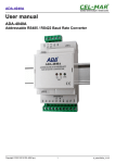
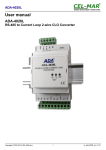
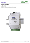
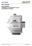
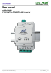
ADA-401WP
User manual
ADA-401WP
1-WIRE to MODBUS-RTU Measuring Module
Copyright © 2001-2017 CEL-MAR sp.j.
1
io_ada-401wp_v.1.24_en
ADA-401WP
Contents
1. GENERAL INFORMATION...................................................................................................................................................................... 4
1.1. WARRANTED INFORMATION....................................................................................................................................................... 4
1.2. GENERAL CONDITIONS FOR SAFE USE.................................................................................................................................... 4
1.3. CE LABEL....................................................................................................................................................................................... 4
1.4. ENVIRONMENTAL PRESERVATION............................................................................................................................................ 4
1.5. SERVICE AND MAINTENANCE..................................................................................................................................................... 4
1.6. PACK CONTENTS.......................................................................................................................................................................... 4
2. PRODUCT INFORMATION..................................................................................................................................................................... 4
2.1. PROPERTIES................................................................................................................................................................................. 4
2.2. DESCRIPTION................................................................................................................................................................................ 5
2.3. APPLICATION................................................................................................................................................................................ 6
2.4. ISOLATION..................................................................................................................................................................................... 6
3. INSTALLATION....................................................................................................................................................................................... 6
3.1. ASSEMBLING................................................................................................................................................................................. 6
3.2. CONNECTION TO COMPUTER..................................................................................................................................................... 6
3.3. CONNECTION TO RS485 / RS422 NETWORK............................................................................................................................ 6
3.3.1. GND TERMINAL CONNECTION........................................................................................................................................... 7
3.3.2. LINE TERMINATION.............................................................................................................................................................. 7
3.4. CONNECTION TO 1-WIRE NETWORK......................................................................................................................................... 7
3.4.1. CONNECTION TEMPERATURE SENSORS......................................................................................................................... 7
3.4.2. SUPPORTED SENSORS WITH 1-WIRE INTERFACE.........................................................................................................8
3.4.3. SUPPORTED CIRCUITS WITH 1-WIRE INTERFACE..........................................................................................................8
3.4.4. 1-WIRE NETWORK LIMITATION.......................................................................................................................................... 8
3.5. POWER SUPPLY CONNECTION.................................................................................................................................................. 8
4. ACTIVATION........................................................................................................................................................................................... 9
4.1. ERRORS SIGNALIZATION............................................................................................................................................................ 9
5. CONFIGURATION................................................................................................................................................................................... 9
5.1. OPERATING MODES..................................................................................................................................................................... 9
5.2. GENERAL CONFIGURATION...................................................................................................................................................... 10
5.2.1. SYSTEM ALARMS............................................................................................................................................................... 10
5.2.2. RS485 CONFIGURATION................................................................................................................................................... 10
5.2.3. 1-WIRE CONFIGURATION.................................................................................................................................................. 11
5.2.4. MEASUREMENT CONFIGURATION................................................................................................................................... 11
5.2.5. AUTOMATIC ASSIGN SENSORS TO MEASUREMENT CHANNELS (AAS) CONFIGURATION......................................11
5.3. MEASURING CHANNEL CONFIGURATION............................................................................................................................... 11
5.3.1. SENSOR ADDING............................................................................................................................................................... 11
5.3.2. CHANGING SENSORS ORDER.......................................................................................................................................... 13
5.3.2.1. SENSOR DISPLACEMENT......................................................................................................................................... 13
5.3.2.2. SENSORS EXCHANGE.............................................................................................................................................. 13
5.3.2.3. CHANGING TEMPERATURE SENSORS ORDER BY THE USE OF AAS PROCEDURE........................................13
5.3.3. SENSORS REMOVING....................................................................................................................................................... 14
5.3.4. MEASUREMENT CHANNEL PARAMETERS CONFIGURATION.......................................................................................14
5.4. SAVING TO FILE.......................................................................................................................................................................... 14
5.5. PRINTING OF CONFIGURATION................................................................................................................................................ 15
5.6. FIRMWARE UPDATE................................................................................................................................................................... 15
5.7. EMERGENCY FIRMWARE UPDATE........................................................................................................................................... 15
5.8. FACTORY DEFAULT.................................................................................................................................................................... 16
6. DIAGNOSTICS...................................................................................................................................................................................... 16
6.1. GENERAL MODULE DIAGNOSTICS........................................................................................................................................... 16
6.1.1. RS485 INTERFACE DIAGNOSTICS................................................................................................................................... 17
6.1.2. 1-WIRE INTERFACE DIAGNOSTICS.................................................................................................................................. 17
6.1.3. ADDITIONAL DIAGNOSTICS OF 1-WIRE BUS.................................................................................................................. 17
6.1.4. SYSTEM DIAGNOSTICS..................................................................................................................................................... 17
6.2. DIAGNOSTIC OF MEASUREMENT CHANNELS........................................................................................................................ 17
6.3. DIAGNOSTIC OF MODBUS PROTOCOL.................................................................................................................................... 18
6.3.1. CONFIGURATION OF MODBUS-RTU COMMUNICATION................................................................................................19
6.3.2. MODULE MONITORING- MODBUS-RTU...........................................................................................................................20
7. IMPLEMENTATION OF MODBUS-RTU PROTOCOL........................................................................................................................... 20
7.1. TABLE OF MODBUS-RTU ADDRESSES.................................................................................................................................... 21
7.1.1. MODBUS REGISTERS MEASURING CHANNELS READOUT BY FUNCTION 04 (3X – REFERENCES) INPUT
REGISTERS OR FUNCTION 03 (4X – REFERENCES) HOLDING REGISTERS........................................................................21
7.2. FRAME STRUCTURE OF MODBUS-RTU PROTOCOL..............................................................................................................22
7.3. USED FUNCTIONS OF MODBUS-RTU PROTOCOL..................................................................................................................22
7.3.1. READOUT OF THE VALUES FROM THE MEASUREMENT CHANNELS..........................................................................22
7.3.1.1. FUNCTION 0x03 / 0x04 – READOUT OF TEMPERATURE FROM MEASURING CHANNEL [4X / 3XREFERENCES]........................................................................................................................................................................ 22
7.3.1.2. FUNCTION 0x03 / 0x04 – READOUT OF RELATIVE HUMIDITY FROM MEASURING CHANNEL [4X / 3XREFERENCES]........................................................................................................................................................................ 23
2
ADA-401WP
7.3.1.3. FUNCTION 0x03 / 0x04 – READOUT OF ATMOSPHERIC PRESSURE FROM MEASURING CHANNEL [4X / 3XREFERENCES]........................................................................................................................................................................ 23
7.3.1.4. FUNCTION 0x03 / 0x04 – READOUT OF LIGHTING FROM MEASURING CHANNEL [4X / 3X-REFERENCES]....23
7.3.1.5. FUNCTION 0x03 / 0x04 – READOUT OF SUNLIGHT FROM MEASURING CHANNEL [4X / 3X-REFERENCES]...24
7.3.1.6. FUNCTION 0x03 / 0X04 – READOUT OF TEMPERATURE SET IN TEMPERATURE ADJUSTER FROM
MEASURING CHANNEL [4X / 3X-REFERENCES]................................................................................................................. 24
7.3.1.7. FUNCTION 0x03 / 0X04 – READOUT OF PERCENTAGE VALUE SET IN PERCENT ADJUSTER FROM
MEASURING CHANNEL [4X / 3X-REFERENCES]................................................................................................................. 24
7.3.1.8. FUNCTION 0x03 / 0x04 – READOUT OF CO2 CONCENTRATION MEASURING CHANNEL [4X / 3XREFERENCES]........................................................................................................................................................................ 24
7.3.1.9. FUNCTION 0x03 / 0x04 – READOUT OF TEMPERATURE VALUE OF SENSOR PT100 , PT500, PT1000 FROM
MEASURING CHANNEL [4X / 3X-REFERENCES]................................................................................................................. 24
7.3.1.10. FUNCTION 0x03 / 0x04 – READOUT OF VOLTAGE VALUES 0-10V DC FROM MEASURING CHANNEL [4X / 3XREFERENCES]........................................................................................................................................................................ 24
7.3.1.11. FUNCTION 0x03 / 0x04 – READOUT OF AMPERAGE VALUES 0-20mA DC FROM MEASURING CHANNEL [4X /
3X-REFERENCES]................................................................................................................................................................... 24
7.3.2. FUNCTION 0X03 / 0X04 - READOUT OF CIRCUIT SERIAL NUMBER FROM MEASURING CHANNEL [4X / 3XREFERENCES].............................................................................................................................................................................. 25
7.3.3. FUNCTION 0X03 / 0X04 - READOUT OF MEASURING CHANNEL STATUS [4X / 3X-REFERENCES]...........................26
8. SPECIFICATION................................................................................................................................................................................... 27
3
ADA-401WP
1. GENERAL INFORMATION
Thank you for your purchase of CEL-MAR Company product. This product has been completely tested and is covered by a two year
warranty on parts and operation from date of sale.
If any questions or problems arise during installation or use of this product, please do not hesitate to contact Technical Support at +48
41 362-12-46 or e-mail [email protected].
1.1. WARRANTED INFORMATION
ADA-401WP module is covered by a two year warranty from date of sale. The warranty does not cover damage caused from improper
use, materials consumption or any unauthorized changes. If the product does not function (is damaged), or not operate in accordance
with the instructions will be repaired.
All warranty and no warranty repairs must be returned with paid transport and insuring to the CEL-MAR Company.
CEL-MAR Company under no circumstances won't be responsible for ensuing damage from improper using the product or as a result
of random causes: the lightning discharge, the flood, the fire and the like.
CEL-MAR Company is not be held responsible for damages and loss including: loss of profits, loss of data, pecuniary losses ensuing
from using or the impossibility of using this product.
In specific cases CEL-MAR Company discontinue all warranties and in particular do not follow the user manual and do not accept
terms of warranty by the user.
1.2. GENERAL CONDITIONS FOR SAFE USE
The device should be installed in a safe and stable places (eg, electroinstallation cabinet), the powering cable should be arranged so
as not to be exposed to trampling, attaching, or pulling out of the circuit.
Do not put device on the wet surface.
Do not connect devices for nondescript powering sources,
Do not damage or crush powering wires.
Do not make connection with wet hands.
Do not adapt, open or make holes in casings of the device!
Do not immerse device in water or no other liquid.
Do not put the fire opened on device sources: candles, an oil lamps and the like.
Complete disable from the supply network is only after disconnecting the power supply circuit voltage.
Do not carry out the assembly or disassembly of the device if it is enabled. This may result to short circuit and damage the device.
The device can not be used for applications that determine human life and health (eg. Medical).
1.3. CE LABEL
The CE symbol on the device CEL-MAR means compatibility with electromagnetic compatibility Electromagnetic
Compatibility Directive EMC 2014/30/WE. Declaration of Conformity is available by contact with Technical Service
(email: [email protected]; phone: +48 41 362-12-46)..
1.4. ENVIRONMENTAL PRESERVATION
This sign on the device inform about putting expended device with other waste materials. Device should send to the
recycling. (In accordance with the act about the Electronic Appliance Expended from day 29 of July 2005)
1.5. SERVICE AND MAINTENANCE
The ADA-401WP module does not require the servicing and maintenance.
Technical support is available at number +48 41 362-12-46 in 8.00-16.00, from Monday to Friday or e-mail [email protected].
1.6. PACK CONTENTS
Module is delivered with: User Manual, Line terminators 120W (2 pcs), CD-ROM with ADAUtil software.
2. PRODUCT INFORMATION
2.1. PROPERTIES
●
●
●
●
●
●
●
●
●
●
●
●
●
●
●
●
●
Possibility of creating networks on the basis of RS485 bus to which are being connected 1-wire sensors,
1-WIRE to MODBUS-RTU protocol conversion,
Supporting 1-WIRE interface circuits: DS1820, DS18S20, DS18B20, DS1822, DS2438Z, DS2401.
Temperature, humidity and atmospheric pressure measurement from the 64 digital sensors,
300m 1-WIRE bus distance - depend on sensor's number and connection method of them and cables,
Accuracy dependent on sensor's selection: for DS1820, DS18S20 – 0,50°C; for DS18B20, DS1822 – 0,0625°C,
RS-485 network baud rate up to 230,4 kbps,
1-WIRE network baud rate: Standard up to 16,3 kbps, Overdrive up to 142 kbps,
Stable power supply 10-30 VDC, power consumption up to 3W, depend on sensors number and type,
3kV= galvanic isolation between RS-485 interface and power supply,
~3kV= opto-isolation in signal channel between RS-485 and 1-WIRE interface,
Protection against power supply reverse connection,
Integrated short circuit protection and over-voltage protection on RS-485 and 1-WIRE networks,
Screw terminal block connectors for all connections,
DIN 43880 standard - mounting in typical electro-installation unit,
Rail mounting according to DIN35 / TS35 standard,
Dimensions (W x D x H) 53mm x 62mm x 90mm.
4
ADA-401WP
2.2. DESCRIPTION
The use of 1 wire digital sensors eliminates the influence of cable length on the measurement process that usual affects analog
methods of temperature, humidity or pressure measurement and signal processing. Digital sensors transmit the measure value by
data transfer protocol and this simplifies connection wiring of a large number of sensors and improves the detection of faulty
components. Traditionally, it has been difficult to operate 1-WIRE data bus sensors in industrial environments. The solution to this
problem is ADA-401WP addressable measurement module with MODBUS-RTU protocol. The ADA-401WP is robust and modular in
design to operate 1-WIRE sensors in a industrial controller environment.
Using ADA-401WP as a addressable node of 1-WIRE bus lets extend the distance up to 1200m between 1-WIRE devices and PC
with monitoring software e.g. SCADA or other MASTER type device (PLC controller). ADA-401WP is equipped with a screw terminal
blocks for twisted pair connections 1-Wire bus and RS-485, as well as for power. Overvoltage protection on each RS-485 line is made
on the basis of 600W protectors diodes and fuses. To RS485 Bus can be connected 32 devices ADA-401WP.Additional converter
like ADA-I1040 (RS232 to RS485) or ADA-I9140 (USB to RS485) enables monitoring of the modules via RS232 or USB interface of
PC with software as AdaUtil or SCADA.
Using:
- the ADA-4040 repeater to connect another 32 modules and extend RS485 bus up to 1200m,- the ADA-4044H HUB RS485, to
connect up to 128 modules, change RS485 bus topology from linear to star - Each arm of the star can have length 1200 meters
- ETHERNET to RS485 converter (ADA-13040) or Wi-Fi to RS485/422 converter (ADA-14040) you can connect ADA-401WP modules
of any location to monitoring or controlling systems.
The ADA-401WP offers a low power wide input voltage range from an external source of greater than 10V to a maximum of 30V and
can be delivered from power pack (e.g. DR-15-12). The module has built in reverse polarity protection to protection against opposite
polarization of power supply.
RS-485 4-wires
or RS-422
RX-
RX+
TX- /B
10mm
GND
TX+ /A
RS-485
2-wires
(SW1)
(RS485/RS422)
90mm
ADA-401WP
MEASURING MODULE
1-WIRE TO MODBUS-RTU
RX
TX
PWR
1-WIRE
10mm
V+
V-
NC
10 – 30
VDC
GND
1-W
VDD
NC
NC
NC
NC
(1-WIRE)
Power Supply
10 - 30 VDC
1-WIRE bus
53mm
Fig. 1. ADA-401WP view
5
62mm
ADA-401WP
2.3. APPLICATION
ADA-401WP measurement module is ideal for applications involving:
- multi-point temperature registration and control,
- controlling of functioning of air-conditioning and heating
- temperature monitoring for HACCP norm,
- temperature monitoring in cereal silo, storehouses, cold stores, drying rooms,
- intelligent buildings.
2.4. ISOLATION
ADA-401WP has 2-way 3kV= galvanic isolation.
2-WAY ISOLATION
RS485/RS422
1-WIRE
POWER SUPPLY
10 - 30VDC
Fig 2. Isolation structure in ADA-401WP
3. INSTALLATION
This chapter will show how to use and connect ADA-401WP to computer, RS485/RS422 networks, 1-WIRE network and power
supply. In the purpose of minimization of disruptions from environment is being recommended to:
● apply multipair type shielded cables, which shield can be connected to the earthing on one end of the cable,
● arrange signal cables in the distance not shorter than 25 cm from powering cables.
● apply cable for the power of adequate cross-section due to voltage drops for converter powering,
● not supply converter from power circuit device that generates large impulse interference such as transmitters, contactors,
3.1. ASSEMBLING
ADA-401WP enclosure is adapted to assembly on TS-35 (DIN35) rail. To install should be mounted device on the rail, upper part of
the enclosure, then press bottom part to hear characteristic „Click” sound.
3.2. CONNECTION TO COMPUTER
Use a RS232 to RS485 converter (like ADA-I1040), or USB to RS485 (like ADA-I9140) to connect ADA-401WP module to computer.
Fig.3 and Fig.4 (below) shows example connection.
3.3. CONNECTION TO RS485 / RS422 NETWORK
It is possible to connect 32 devices to RS485 network according to EIA-485 standard with total cable length of 1200m. To extend
length of the network or increase the number of device should be used repeater or hub eg. ADA-4040, ADA-4044H.
Typical connections of ADA-401WP to RS485 network are shown on figure below.
PC
RS232
Connector
(2) Rx
(3) Tx
(5) GND
ADA-I1040
RS232
RS485/RS422
Connector
Connector
Tx (2)
Rx (3)
GND (5)
RS485(4W) Bus
Tx+/ A
Rt Tx-/ B
Rx+
Rt
RxGND
ADA-401WP
ADA-401WP
Fig 3. Example connection to RS485 4-wire network
6
ADA-401WP
ADA-401WP
PC
ADA-I1040
RS232
Connector
RS232
RS485/RS422
Connector
Connector
(2) Rx
(3) Tx
(5) GND
Tx (2)
Rx (3)
GND (5)
RS485(2W) Bus
Tx+/ A
Rt
Tx-/ B
Rx+
RxGND
ADA-401WP
ADA-401WP
ADA-401WP
Fig 4. Example connection to RS485 2-wire network
3.3.1. GND TERMINAL CONNECTION
Connection of GND terminals of RS485/422 interfaces, devices connected to RS485/422 bus, should be done in the case of a
potential difference of the signals grounds on interfaces RS485 / RS422, which prevents proper data transmission.
Cannot connect to the GND terminal - cables screens, PE circuit of electrical installation, signals grounds of other devices.
3.3.2. LINE TERMINATION
Using Line Termination (terminator) Rt = 120W will reduce electrical reflection in data line at high baud rate. It is not needed below
9600Bd. Should be used Line Termination resistor if the distance is over 1000m @ 9600Bd or 700m @ 19200Bd transmission.
Example connection of Rt (connected to screw terminal block of RS485/422 interface) are shown on Fig. 3 & 4.
3.4. CONNECTION TO 1-WIRE NETWORK
3.4.1. CONNECTION TEMPERATURE SENSORS
Connections of 1-wire temperature sensors to ADA-401WP module are shown below.
ADA-401WP
RS485/RS422
1-WIRE
Connector
Connector
Tx+/ A
Tx-/ B
Rx+
RxGND
1-WIRE (3W) Bus
GND
1-W
VDD
Vss+
Vss-
VV+
10–30VDC
3W
Power Supply
DS18B20 Sensor
DS18B20 Sensor
DS18B20 Sensor
Fig 5. Sensor connection to ADA-401WP module with (3-wire) 1-WIRE network
7
ADA-401WP
ADA-401WP
RS485/RS422
1-WIRE
Connector
Connector
Tx+/ A
Tx-/ B
Rx+
RxGND
1-WIRE (2W) Bus
GND
1-W
VDD
Vss+
Vss-
VV+
10–30VDC
3W
Power Supply
DS18B20 Sensor
DS18B20 Sensor
DS18B20 Sensor
Fig 6. Sensor connection to ADA-401WP module with (2-wire) 1-WIRE network
3.4.2. SUPPORTED SENSORS WITH 1-WIRE INTERFACE
To ADA-401WP module can be connected devices like :
– based on circuits: DS1820, DS18S20, DS18B20, DS1822, DS2438Z, DS2401,
– temperature sensors DTS-103 & DTS107,
– environmental parameter sensor DES-200 (temperature, relative humidity, atmospheric pressure),
– environmental parameter sensor DES-216 (temperature, relative humidity, atmospheric pressure, lighting),
– environmental parameter sensor DES-300 (temperature, relative humidity, atmospheric pressure, lighting, sunlight, CO2
concentration),
– PT100 sensor to 1-WIRE converter DES-216-PT100,
– PT500 sensor to 1-WIRE converter DES-216-PT500,
– PT1000 sensor to 1-WIRE converter DES-216-PT1000,
– Analog signal 0-10V DC to 1-WIRE converter DES-216-U,
– Analog signal 0-20mA DC to 1-WIRE converter DES-216-I,
Method of connection above sensors to ADA-401WP is shown in user manuals of above devices.
3.4.3. SUPPORTED CIRCUITS WITH 1-WIRE INTERFACE
ADA-401WP module supports 1-WIRE interface circuits like: DS1820, DS18S20, DS18B20, DS1822, DS2438Z, DS2401.
In preparation DS2401 circuit.
3.4.4. 1-WIRE NETWORK LIMITATION
The maximum length of 1-WIRE network as layouts producer can be even 400m and the maximum number of sensors can be 500.
However, when building the network, remember that, each sensor is a shortening of 0,5 meters and 100 meters of cable causes
additional capacity load data line 5nF increasing signal distortion.
The real 1-WIRE network length and number of sensors will be less and will depend on:
– type of cables,
– topology connections,
– quality connections,
– interference from external electromagnetic fields.
–
–
–
–
–
RECOMMENDATIONS :
using one type of the cable, we recommend computer twisted cables UTP 4x2x0,5, for 1-WIRE bus,
1-WIRE network connection in linear topology or use the passive 1-WIRE network splitter DNB-400,
ending the 1-WIRE network by sensor,
connecting unused wires and screen cable to PE rail of electrical installation.
powering ADA-401WP module from individual power supply.
3.5. POWER SUPPLY CONNECTION
The power supply to ADA-401WP module should be DC (regulated) from 10 V to 30V and minimum nominal power should be 3W,
e.g. ZS-12/250 or DR-15-12. Power cable from DC power supplies to device must not be longer than 3m.
Observe the polarity, connect positive (+) of DC power supplies to V+ and negative (-) end to V- terminal. ADA-401WP has the
protection from opposite connection power supply. If after power, on the front panel is not lit green LED PWR, check the power
connection (polarity).
8
ADA-401WP
4. ACTIVATION
After properly connection according to section above the module can be powered. Once activated the green LED PWR on front panel
of the module should light. If after connection power supply LED will not light green, check the correctness of connecting power
supply. When data is present on the 1-WIRE bus the Tx and Rx LED should blink. A summary table of LED indications is listed below.
LED
Description
PWR
Signalization of Power Supply
Rx
Signalization of data transmission from ADA-401WP through 1-WIRE interface
Tx
Signalization of data receiving by ADA-401WP from 1-WIRE interface
4.1. ERRORS SIGNALIZATION
When works ADA-401WP module, may signal a short sound for different types of errors like:
- errors of sensors searching,
- errors of reading temperature from sensors,
- errors in RS485 communication,
- errors of CRC sensors serial number,
- short circuit on 1-WIRE network,
- no sensor,
- no 1-WIRE network controller.
The reasons of those errors can be found in ADAUtil software, checking:
- RS485 interface Diagnosis,
- 1-WIRE interface Diagnostic,
- System Diagnostic,
- Measurement channels Diagnostic
5. CONFIGURATION
Configuration of ADA-401WP module should be made by the use of ADAUtil software – delivered whit the module.
To make configuration, connect ADA-401WP to a PC (according to point CONNECTION TO COMPUTER) and be the power. If after
power, on the front panel is not lit green LED PWR, check the power connection (polarity).
Once powered correctly, the module must be set to configuration mode by the use of the switch SW1, as shown in the table below.
SW1-1
ON
SW1-2
OFF
Yellow LED will blink with frequency 1 Hz. The yellow LED is located alongside the SW1 switch, under the upper terminal block
connector cover.
5.1. OPERATING MODES
All available modes are shown in table below:
SW1- 1
SW1- 2
Mode
OFF
OFF
Run (Modbus)
OFF
ON
Factory Default (see chapter FACTORY DEFAULT)
ON
OFF
Configuration, Firmware Update (see chapter FIRMWARE UPDATE)
ON
ON
Emergency Firmware Update (see chapter EMERGENCY FIRMWARE UPDATE.)
To select operating mode, the SW1 micro-switch should be set in correct position. This micro-switch is available after removing upper
terminal block cover (Fig. 1).
9
ADA-401WP
5.2. GENERAL CONFIGURATION
Fig 7. View of general configuration ADAUtil window
Main configuration is started by setting SW1 micro switch in configuration mode as follows:
SW1-1
SW1-2
ON
OFF
Yellow LED will blink with frequency 1 Hz.
Run ADAUtil software and select branch Configuration=>Communication on left panel and on right select COM port used for
module configuration. Then select branch Configuration=>Communication=>ADA-401WP on left panel and on right press [Read
Configuration form Module]. Set the parameters in the following sections.
5.2.1. SYSTEM ALARMS
Section System Alarms has option:
Enabling sound alarm for module error operation – enable or disable (disable - manufacturer setting).
Errors that are signalled by short sound:
– errors of sensors searching,
– errors of reading temperature from sensors,
– errors in RS485 communication,
– errors of CRC sensors serial number,
– short circuit on 1-WIRE bus,
– no sensor,
– no 1-WIRE bus controller.
5.2.2. RS485 CONFIGURATION
Section RS485 bus has options:
– Communication Protocol - allows choice of protocol (at the moment available - MODBUS RTU-SLAVE)),
– Module address – setting module address for selected protocol from range 1 to 247 (64 - manufacturer setting),
– Baud rate: 300bps – 230400bps (9600bps – factory default),
– Data bits number: 8 bits (readout only),
– Parity control: none, even parity, different parity, (non – factory default),
– Stop bits number: 1-bit or 2-bits (1-Bit – factory default),
– Interval between frames in bytes: 4 – 255, for MODBUS RTU protocol 4-character – factory default.
10
ADA-401WP
5.2.3. 1-WIRE CONFIGURATION
Section 1-WIRE bus has options:
– Baud rate: standard (at the moment available is standard baud rate),
– Number of groups in searching process: readout only,
– List of available group of 1-WIRE sensor/systems in searching process (readout only).
5.2.4. MEASUREMENT CONFIGURATION
Section Measurement configuration has options:
– Measuring data format: integral number with 2-byte (readout only),
– Pause between readout: interval between another readout of measurement from connected sensors - range 1 – 255 sec.
– Enable single reading sensors: enable this option causes that each sensor is readout separately. The time of readout one sensor
is about 1 sec.
The effect of this option is:
- extension measurement readout time from sensors,
- reducing current value, being in VDD line or DQ, to current value one sensor in time of measurement processing. It is imported in
potentially explosive environments, after connection an intrinsically safe barrier to ADA-401WP.
– Enable write TL and TH registers for DS18xxx: enable this option causes that change of Lo and Hi values in the configuration on
measurement channel is write in TL and TH registers of DS18xxx sensor and readout from these registers. Disable this option
causes that Lo and Hi values setted in the measurement channel configuration are written to ADA-401WP memory and readout
from there.
Options Enable single reading sensors and Enable write TL and TH registers for DS18xxx are available from 2,005 firmware
version and 1.7.1.0 version of ADAUtil.
5.2.5. AUTOMATIC ASSIGN SENSORS TO MEASUREMENT CHANNELS (AAS) CONFIGURATION
AAS function lets quickly assign sensors to measuring channels in the order specified by their heating temperature AAS. Description
of using the AAS function is described in point CHANGING SENSORS ORDER BY THE USE OF AAS PROCEDURE
Configuration of AAS function :
- Enable Automatic Assign Temperature Sensor to Measure Channel: enable or disable module AAS function,
- Temperature AAS: 0 – 50 °C, - setting of AAS temperature above followed by automatic assignment of the sensor to a channel.
After configuration press button Save configuration to module.
Set SW1 switch section to run mode as in the table below.
SW1-1
OFF
SW1-2
OFF
Yellow LED will be OFF.
5.3. MEASURING CHANNEL CONFIGURATION
Set the SW1 micro switch in the configuration mode as table below
SW1-1
SW1-2
ON
OFF
Yellow LED will blink with frequency 1 Hz.
5.3.1. SENSOR ADDING
After connecting sensors to ADA-401WP, according to point CONNECTION TEMPERATURE SENSORS and running ADAUtil
software, select branch Configuration=>Communication on left panel, and on right select COM port used for module configuration.
Then on left panel select branch Configuration=>Communication=>ADA-401WP=>Measure channels and on right will open
[Measure channels configuration and diagnostic] and press [Read Configuration form Module] – readout the configuration of
measurement channels from ADA-401WP.
11
ADA-401WP
Fig 8. View of ADAUtil measuring channel configuration window
After readout the configuration of measurement channels, serial numbers of all searched sensors will be presented in the column
Sensor SN.
The numbers of channel are assigned in order of search by the module.
Correctly identified sensor is assigned the appropriate unit of measure in column [U.m.] as in the table below.
Table indications of sensors
Sensor
Unit of
measurement
Sensor
Unit of
measurement
Temperature
°C
voltage converter 0-10V DC
V U10
Relative humidity
%RH
current converter 0-2mA DC
mA A20
Atmospheric pressure
hPa
DS2401 circuit serial number
S/N
Lighting (natural or unnatural)
%Lux
Unrecognised sensor
???
Sunlight
%SLux
Temperature adjuster
(TA)°C
Percentage adjuster
(PA)%
CO2 concentration (in preparation)
CO2 ppm
Sensor transducer PT100 to 1-WIRE
°C PT100
Sensor transducer PT500 to 1-WIRE
°C PT500
Sensor transducer PT1000 to 1-WIRE
°C PT1000
12
ADA-401WP
If before readout the configuration of measure channels, were not connected temperature sensors to the module, the list of the column
[U.m.] will be empty. In this case, connect sensor (s) to ADA-401WP and again readout the configuration of measurement channels
from ADA-401WP memory, by pressing [Read Configuration form Module].
Adding next sensors, consist in connecting them to the module and readout the configuration of measurement channels from ADA401WP memory, by pressing [Read Configuration form Module].
ATANTION!!
If wish to new added sensors were assigned to further measurement channels, should set Assigned for before added sensors, and
save the channel configuration to the module by pressing [Save Configuration to Module].
After adding all sensors to the measurement channels, should be set an order of sensors and make the configuration of
measurements channels as described below.
5.3.2. CHANGING SENSORS ORDER
The order of sensors can be changed by:
- sensor displacement,
- sensors exchange,
- AAS procedure.
All above method are described below.
5.3.2.1. SENSOR DISPLACEMENT
To displacement the sensor from one channel to the other, under button Move Sensor from Channel to Channel, enter to field from
the number of channel from which the sensor will be moved and to field to enter the number of channel to which the sensor will be
moved. Press the button Move Sensor from Channel to Channel.
Save the configuration to module memory by pressing button Save Configuration to Module.
To the module memory will be saved only configuration of measuring channels which fields were marked in ping.
5.3.2.2. SENSORS EXCHANGE
To exchange the sensors enter to the fields from and on the channel number to which will be exchange the sensors and press the
button Exchange Sensors from Channel on Channel. Save the configuration to module memory by pressing button Save
Configuration to Module.
To the module memory will be saved only configuration of measuring channels which fields were marked in ping.
5.3.2.3. CHANGING TEMPERATURE SENSORS ORDER BY THE USE OF AAS PROCEDURE
If the location of sensors in the installation is unknown, can be added to measurement channel by using Automatic Assign Sensor
function.
The procedure of Automatic Assign Sensor (AAS) is made in the following steps:
1. Connect 1-WIRE sensors bus to ADA-401WP.
2. Select (in the ADAUtil software) branch Configuration => Communication =>ADA-401WP on left panel and on right press Read
Configuration form Module.
3. In section Automatic Assign Temperature Sensor to Measure Channel select option Enable Automatic Assign Temperature
Sensor to Measure Channel, then in edition field Temperature AAS, enter the upper temperature limit beyond which it will
automatically assign a heated sensor to the measurement channel. The sensors are assigned sequentially to the channel number
0, 1, 2, 3 … e.t.c.
4. Press button Save configuration to module.
5. Select branch Configuration => Communication =>ADA-401WP => Measure Channels on left panel and on right press Read
Configuration form Module.
6. After readout the configuration press Sensors Monitoring.
7. Then heat sensors in the selected order (e.g. as fig. below) and if sensor temperature exceeds the setted temperature AAS,
sensor will be automatically assign for measuring channel. Any assignment of a sensor for measuring channel is indicated by the
module and program of short tone/Beep.
8. This procedure is ended by pressing again the button Sensors Monitoring.
9. Select branch Configuration => Communication =>ADA-401WP, then in section Automatic Assign Temperature Sensor to
Measure Channel, disable the option Enable Automatic Assign Temperature Sensor to Measure Channel.
10. Press button Save Configuration to Module. It will disable the algorithm of Automatic Assign Sensor to Measuring Channel
in ADA-401WP module.
13
ADA-401WP
Illustration of APC procedure
ADA-I1040
RS232 / RS485
RS485 network
RS232 or USB
or
ADA-I9140, ADA-I9141
USB / RS485
1-WIRE network up to 100m
with DS18S20 sensors
The order of assignment
sensors to measuring
channels
before:
4
2
1
9
8
7
5
3
6
0
and after :
0
1
2
3
4
5
6
7
8
9
ending APC procedure
the direction of heat sensors
4
- Measuring channel number
Heat source
e.g. hair dryer.
Fig 9. Visualization of I Automatic Assign Temperature Sensor to Measure Channel
5.3.3. SENSORS REMOVING
Double click on the field Sensor SN of channel, and press the Delete key of a keyboard and go to next field. Save the configuration to
module memory by pressing button Save Configuration to Module.
To the module memory will be saved only configuration of measuring channels which fields were marked in ping.
5.3.4. MEASUREMENT CHANNEL PARAMETERS CONFIGURATION
After ended adding and changing sensors order, can be configured other parameters of measuring channels. Successively fill in fields:
Location – enter a location of installed sensors, maximum 9 characters.
Val.Lo – value of lower limit measure value. If the value measured by sensor will be lower, that will be setted the byte of exceed lower
threshold V<VL in the register of measurement channel.
Val.Hi – value of high limit measure value. If the value measured by sensor will be higher, that will be setted the byte of exceed upper
threshold V>VL in the register of measurement channel.
Offset – The value of which will be increased or decreased the value measured by the sensor measurement to a linear calibration
measurement. The offset depends on the type of sensor:
- from -1.27°C to +1.27°C for digital temperature sensors DTS-RJ45, DTS-103, DTS-107, DES-300-T, DES-300E-T,
- from -12.70%Hig to +12.70%Hig for digital relative humidity sensors: DES-216-H, DES-300-H etc.,
- from -12.70hPa to +12.70hPa for digital atmospheric pressure sensors: DES-216-AP, DES-300-AP etc.
Enable – activation this field will cues actualisation of measurement and status for channel, deactivation will cues block actualisation.
Assigned - activation this field will cues adding a sensor to the Channel. Deactivation will cues that in case of next sensors searching
by the module in field [Sensor SN] channel can be serial number or other sensor.
Each proper changing of the list's field of table Measuring Channel Configuration is causing highlighting of data of the measuring
channel to the ping color.
Save the configuration to module memory by pressing button Save Configuration to Module.
To the module memory will be saved only configuration of measuring channels which fields were marked in ping.
Set the SW1 switch section to run mode as in the table below.
SW1-1
OFF
SW1-2
OFF
Yellow LED will be OFF.
5.4. SAVING TO FILE
Main configuration and measurement channel configuration can be saved to a configuration file. It lets to save the configuration of
each measuring module of the system. Choose from menu Configuration => Save or Save As, and a window Save As will open
(fig.10). Enter the file name in the field File Name and press button Save.
14
ADA-401WP
Fig 10. Saving of module configuration
5.5. PRINTING OF CONFIGURATION
To print the main configuration and measurement channels, select in left window the branch Configuration => Communication =>
ADA-401WP => Measuring Channels and then select from the menu Configuration =>Print or Print View.
5.6. FIRMWARE UPDATE
Set the SW1 micro switch to configuration mode – table below
SW1-1
SW1-2
ON
OFF
Yellow LED will blink with frequency 1 Hz (the yellow LED is located alongside the SW1 switch, under the upper terminal block
connector cover).
Run ADAUtil software and select Configuration => Communication on left panel and on right select COM port used for changing
software. Then select Configuration => Communication => ADA-401WP and press button Change Firmware, window will open in
which should be selected and opened the *.bin. Software will be load to ADAUtil buffer storage and will be checked. If the ADAUtil not
detect errors in loaded file, can be changed the module software. Process of software update is visualized by ADAUtil in use of
Progress Window and after proper update confirmed by correct message.
Fig. 11. Choice of software file
During loading software the yellow LED located beside SW1 micro-switch will blink, showing data flow to module. If the software
loaded correctly yellow LED will be blink with frequency 1 Hz.
Attention! Do not turn off the power during the firmware updating.
After that set micro switch SW1 to run mode as shown in the table below.
SW1-1
SW1-2
OFF
OFF
Yellow LED will be OFF.
5.7. EMERGENCY FIRMWARE UPDATE
In the case of the unsuccessful update of the module software, try again according to description in point FIRMWARE UPDATE. If the
update is still incorrect use emergency firmware update.
Set the SW1 microswitch to Emergency Firmware Update mode as in the table below.
SW1-1
SW1-2
ON
ON
Restart the module by turning OFF, and after while, turning ON. The yellow LED will light continuously and the module will be in
emergency software mode and now follow the description below:
15
ADA-401WP
Run ADAUtil software and select Configuration => Communication on left panel and on right select COM port used for changing
software. Then select Configuration => Communication => ADA-401WP and press button Change Firmware, window will open in
which can be selected and opened file *.bin. Software will be load to ADAUtil buffer storage and will be checked. If the ADAUtil not
detect errors in loaded file, module software can be changed. Process of software changing is visualized by ADAUtil in use of
Progress Window and after proper changing confirmed by correct message.
Attention! Do not turn off the power during the firmware updating.
After that set micro switch SW1 to RUN mode as shown in the table below.
SW1-1
SW1-2
OFF
OFF
Yellow LED will be OFF.
5.8. FACTORY DEFAULT
In the case, were the module has malfunction as a result of:
- missing communication in the configuration mode,
- value visualization of temperature measurement with the 0,5°C accuracy,
- transmission errors on the 1-WIRE bus,
restore factory default and reset register.
Set the SW1 microswitch as in the table below.
SW1-1
SW1-2
OFF
ON
Then turn off the power and after while, turn on the power of the module. After that to internal registers of the module will be loaded
factory default.
After successful restart of module sw1 switch to RUN mode as in the table below.
SW1-1
SW1-2
OFF
OFF
6. DIAGNOSTICS
6.1. GENERAL MODULE DIAGNOSTICS
Set the switch SW1 to configuration mode as shown in the table below.
SW1-1
ON
SW1-2
OFF
Yellow LED will blink with frequency 1 Hz (the yellow LED is located alongside the SW1 switch, under the upper terminal block
connector cover).
Start the ADAUtil software and in left window select branch Configuration => Communication => ADA-401WP.
In the following sections diagnostic module can be checked correctness of transmission data by RS458 and 1-WIRE interfaces and
stability of functioning of module.
Fig 12. View of main diagnostics of module
16
ADA-401WP
6.1.1. RS485 INTERFACE DIAGNOSTICS
Frame errors counter and parity errors counters are refreshed pressing button Read Counter.
In order to reset the counter from module memory press button Delete Counters.
Frame errors counter - is increased e.g. errors from incorrect speed to actual speed of data transmitted.
Parity error counter – counts errors, which can be from bits corrupted in the transmitted character.
6.1.2. 1-WIRE INTERFACE DIAGNOSTICS
Errors encountered during searching for sensors and errors associated with readout measurements counter are refreshed by pressing
button Read Counter.
To reset the counter in module memory press button Delete Counter.
Errors of searching counter - is increased in case of errors detected from sensor searching process on 1-WIRE network.
Errors of measuring reading counter - is increased in case of detection improper data in process of temperature reading.
6.1.3. ADDITIONAL DIAGNOSTICS OF 1-WIRE BUS
Press button Readout Diagnostics for:
- Short circuits on the network
- The number of detected sensors,
- Network types,
- Correctness’s of communication,
- Detection of 1-WIRE bus converter.
6.1.4. SYSTEM DIAGNOSTICS
It is possible to readout a number of system counters (information about module operation) by pressing the button Read Counters.
Delete the counter in module memory individually of each e.g. Delete WD Counter.
Register counter of WatchDog –the number of restarts of the processor for program WatchDog.
Register counter of Power-On – the number of power cycles of the module.
Register counter of Button – the number of RST (Reset) button.
Register counter of Brown-On – specifies the number of the operating voltage drops below allowable voltage level
After that, can be set the switch section SW1 to RUN mode as in the table below.
SW1-1
SW1-2
OFF
OFF
Yellow LED will be OFF.
6.2. DIAGNOSTIC OF MEASUREMENT CHANNELS
After configuration the measurement channels can be carried out their diagnosis and verify communication on 1-Wire bus.
In the purpose of readout measurement channels diagnostic, set micro switch SW1 to configuration mode as shown in the table
below.
SW1-1
SW1-2
ON
OFF
Yellow LED will blink with frequency 1 Hz.
Start ADAUtil software and select Configuration => Communication on left panel and on right select COM port used for changing
software. Then select Configuration => Communication => ADA-401WP => Measuring Channels, and on right window press
Readout Configuration form Module. Scroll on right, until to see the unit Diagnostic of channels. On the screen are the columns:
Value
U.m.
V<VL
V=>VH
Enable
Assigned
Busy
Detected
CRC
- measurement value readout from the sensor.
- unit of measurement measured by the sensor.
- indicates that the value readout from the sensor is short then the lower limit of the value VL.
- indicates that the value readout from the sensor is equal to the lower limit of the value VH
- indicates that the measurement channel is unblocked and measuring data and the status channel are being
updating systematically.
- indicates that sensor of serial number was assigned to measuring channel.
- indicates that sensor is processing data.
- indicates that the sensor of serial number from field Sensor SN was detected.
- indicates error of CRC sensor memory or connection error.
17
ADA-401WP
Fig 13.View of ADAUtil measuring channel diagnostic window
Readout of channels diagnostic and sensor measurement values by pressing the button Read Sensor Measure and Condition.
Continuous monitoring of measurement channels diagnostic and measuring value from sensors by pressing the button Sensors
Monitoring.
Normal operating of 1-WIRE network :
- no corruption of CRC,
- all connected sensors are detected,
- no readout error temperature.
After that, can be set the switch section SW1 to RUN mode as in the table below.
SW1-1
SW1-2
OFF
OFF
Yellow LED will be OFF.
6.3. DIAGNOSTIC OF MODBUS PROTOCOL
After finishing diagnostic of measurement channels of each ADA-401WP module in installation, can be started diagnostic and
checking of correctness MODBUS protocol communication on RS485 bus. The module should be in the RUN mode – the SW1 micro
switch should be setted like in the table below.
SW1-1
SW1-2
OFF
OFF
Yellow LED will be OFF.
Start the ADAUtil software and in left window select branch Configuration => Communication on left panel, and on right select
COM port used for MODBUS diagnostic. Then select Configuration => Communication => ADA-401WP => MODBUS Monitoring,
on right will be window MODBUS Monitoring.
18
ADA-401WP
Fig 14a. View of MODBUS monitoring window – configuration parameters of channels
Fig 14b. View of MODBUS monitoring window – work parameters of channels
6.3.1. CONFIGURATION OF MODBUS-RTU COMMUNICATION
MODBUS Monitoring window has options for configuration of MODBUS-RTU communication:
Module Address [1-247] - enter the address of ADA-401WP module for MODBUS-RTU protocol.
COM Port
- setted in window Communication.
Baud rate
- to set the baud rate for each module.
19
ADA-401WP
Data bits
Parity
Stop Bits
Timeout
MODBUS function
- not selectable.
- set the type of parity control in data format.
- set the number of stop bits in data format.
- set the timeout in ms.
- set the function for MODBUS-RTU protocol, for communication with ADA-401WP module.
6.3.2. MODULE MONITORING- MODBUS-RTU
MODBUS Monitoring has options for MODBUS-RTU communication:
Monitoring bottom
Pressing this button will cause readout of:
a) configuration parameters of measurement channels like: Sensor S/N, Location, Val. Lo, Val. Hi, Offset, Enable, Assigned,
b) channel diagnostics like: measurement value, status of measurement channel (U.m., V<VL, V>VH, Enable, Assigned, Busy,
Deleted, CRC).
Pressing the button Monitoring again, interrupt the monitoring.
MODBUS communication Log
This section is additional element of diagnostic MODBUS-RTU protocol, where frames of inquiry and respond come out during
measurement monitoring and status of measurement channels are being written.
Table MODBUS Monitoring has columns:
Channel
- the number of measuring channel.
Sensor SN
- serial number of detected sensor.
Location
- place of sensor's installation.
Val. Lo
- low limit of measuring value. If the value measured by sensor will be lower, that will be setted the byte of exceed
lower threshold V<VL in the register of measurement channel.
Val. Hi
- upper limit of measuring value. If the value measured by sensor will be higher, that will be setted the byte of
exceed upper threshold V>VL in the register of measurement channel.
Offset
- value by which will be increased or decreased measured value of measurement for the linear calibration of the
measurement. Offset value depends on sensor type and is:
- from – 1.27°C to +1.27°C for digital temperature sensors: DTS-RJ45, DTS-103, DTS-107, DES-216,
DES-300-T, DES-300E-T etc.,
- from -12.70%Hig to +12.70%Hig for digital relative humidity sensors: DES-216-H, DES-300-H etc.,
- from -12.70hPa to +12.70hPa for digital atmospheric pressure sensors: DES-216-AP, DES-300-AP etc.
Enable
- activation this field will cues actualisation of measurement and status for channel, deactivation will cues block
actualisation.
Assigned
- activation this field will cues adding a sensor to the Channel. Deactivation will cues that in case of next sensors
searching by the module in field [Sensor SN] channel can be serial number or other sensor.
Progress
- horizontal indicator of measuring progression.
Value
- measurement value readout from the sensor.
U.m.
- unit of measurement, measured by the sensor.
V<VL
- indicates that the value readout from the sensor is short then the lower limit of the value VL.
V=>VH
- indicates that the value readout from the sensor is equal to the lower limit of the value VH
Enable
- indicates that the measuring channel is unblocked and measuring data and the channel condition are being
updating systematically.
Assigned
- indicates that sensor of serial number was assigned to measuring channel.
Busy
- indicates that sensor is processing data.
Detected
- indicates that the sensor of serial number from field Sensor SN was detected.
CRC
- indicates error of CRC sensor memory or connection error.
Readout of MODBUS registers for columns: Sensor SN, Location, Val. Lo, Val. Hi, Offset, Enable, Assigned – is available from
2,005 version of firmware and from 1.7.1.0 version of ADAUtil software.
In this table the status of measuring channel are shown by use the colours as follows:
Field [Value]
Red – alarm status of channel, exceed thresholds VH.
Blue - alarm status of channel, exceed thresholds VL.
Green – standard status of measuring channel.
Field [V<VL], [V>VH], [Enable], [Assigned], [Busy], [Detected], [CRC]
Yellow – alarm status of field in measuring channel
White – standard status of field in measuring channel
7. IMPLEMENTATION OF MODBUS-RTU PROTOCOL
ADA-401WP module is a like node for the 1-wire network. Each node can be addressed and connected to RS485 bus, and this allow
working together many dispersed 1-WIRE networks, with remote control system e.g. temperature, humidity, atmospheric pressure CO2
concentration, etc. RS485 bus can be extended on lengths of 1200m, by using the ADA-4040 repeater or ADA-4044H RS485 HUB.
The MODBUS-RTU protocol used for communication between ADA-401WP modules and SCADA type system or PLC controller
20
ADA-401WP
enable easy integration of 1-wire sensors with existing automation systems.
Extended implementation of the MODBUS-RTU protocol is available by contacting the service department.
7.1. TABLE OF MODBUS-RTU ADDRESSES
7.1.1. MODBUS REGISTERS MEASURING CHANNELS READOUT BY FUNCTION 04 (3X –
REFERENCES) INPUT REGISTERS OR FUNCTION 03 (4X – REFERENCES) HOLDING
REGISTERS
Address
3X
(F04)
Address
4X
(F03)
Number of
measuring
channel
Data address
for measuring
channel
Data description
Attribute
Value
Measurement value for measuring channels
30001
40001
0
0
Measurement value
R
16-bit register
30002
40002
1
1
Measurement value
R
16-bit register
30003
40003
2
2
Measurement value
R
16-bit register
30004
40004
3
3
Measurement value
R
16-bit register
30005
40005
4
4
Measurement value
R
16-bit register
30006
40006
5
5
Measurement value
R
16-bit register
30007
40007
6
6
Measurement value
R
16-bit register
30008
40008
7
7
Measurement value
R
16-bit register
30009
40009
8
8
Measurement value
R
16-bit register
...
...
...
...
...
...
30064
40064
63
63
Measurement value
R
16-bit register
Measuring Channel condition
30201
40201
0
200
Channel condition
R
16-bit register
30202
40202
1
201
Channel condition
R
16-bit register
30203
40203
2
202
Channel condition
R
16-bit register
30204
40204
3
203
Channel condition
R
16-bit register
30204
40204
4
204
Channel condition
R
16-bit register
30206
40206
5
205
Channel condition
R
16-bit register
30207
40207
6
206
Channel condition
R
16-bit register
30208
40208
7
207
Channel condition
R
16-bit register
30209
40209
8
208
Channel condition
R
16-bit register
...
...
...
...
...
...
30264
40264
63
263
Channel condition
R
16-bit register
Readout the serial number circuit
The serial number is 8-bytes B0, B1 ... B7
30401
40401
0
400
serial number SN-C00-B0-B1
R
16-bit register
30402
40402
0
401
serial number SN-C00-B2-B3
R
16-bit register
30403
40403
0
402
serial number SN-C00-B4-B5
R
16-bit register
30404
40404
0
403
serial number SN-C00-B6-B7
R
16-bit register
30405
40405
1
404
serial number SN-C01-B0-B1
R
16-bit register
30406
40406
1
405
serial number SN-C01-B2-B3
R
16-bit register
30407
40407
1
406
serial number SN-C01-B4-B5
R
16-bit register
30408
40408
1
407
serial number SN-C01-B6-B7
R
16-bit register
...
...
...
...
...
...
...
30653
40653
63
652
serial number SN-C63-B0-B1
R
16-bit register
30654
40654
63
653
serial number SN-C63-B0-B1
R
16-bit register
30655
40655
63
654
serial numberSN-C63-B0-B1
R
16-bit register
21
ADA-401WP
Address
3X
(F04)
Address
4X
(F03)
Number of
measuring
channel
Data address
for measuring
channel
Data description
Attribute
Value
30656
40656
63
655
serial number SN-C63-B0-B1
R
16-bit register
7.2. FRAME STRUCTURE OF MODBUS-RTU PROTOCOL
Device address (1-byte)
Function (1-byte) Data (n-bytes)
CRC-16Lo (1-byte)
CRC-16Hi (1-byte)
7.3. USED FUNCTIONS OF MODBUS-RTU PROTOCOL
Function code
Description
03 (0x03)
Readout of measurement value and measuring channel condition
04 (0x04)
Readout of measurement value and measuring channel condition
7.3.1. READOUT OF THE VALUES FROM THE MEASUREMENT CHANNELS
7.3.1.1. FUNCTION 0x03 / 0x04 – READOUT OF TEMPERATURE FROM MEASURING
CHANNEL [4X / 3X-REFERENCES]
Function 0x03 / 0x04 are used for readout of the value from measuring channel (sensor).
The mesurement value from measuring channel (sensor) is presented by a 16-bit register.
The registers with measuring value are in the format of 16-bit signed integer (C/C++ type short int).
The real value of temperature in °C (-55 – +125 [°C]) obtained from the read register according to below algorithm by use appropriate
factor value DW=100 (table below):
Unit of
DW factor
Unit of
DW factor
Measured/ adjusted Value
Measured/ adjusted Value
measurement
value
measurement
value
Temperature
°C
100
PT1000 sensor's temperature
°C PT1000
10
Relative humidity
%RH
10
0-10VDC transducer
V U10
100
Lighting (natural or unnatural)
%Lux
10
0-20mADC transducer
mA A20
100
Sunlight
%SLux
10
Circuit DS2401 serial number
S/N
non
Temperature adjuster
(TA)°C
10
Percentage adjuster
(PA)%
10
Atmospheric pressure
hPa
10
CO2 concentration (in preparation)
CO2 ppm
1
PT100 sensor's temperature
°C PT100
10
PT500 sensor's temperature
°C PT500
10
Algorithm 1. Readout register is saved to regular type variable (float) and then divide it by the factor DW
// Fragment of code in C language (VS6.0) presenting above algorithm
short int siMeasurementReg;
float
fMeasurmentValue
......
fMeasurmentValue = (float)siMeasurementRegister;
fMeasurmentValue = fMeasurmentValue / DW;
Algorithm 2. Readout register is saved to regular type variable 16-bit (short int) and then divide by the factor DW, received change
of the dividing it is a number of the hundredth parts of the measurement value.
// Fragment of code in C language (VS6.0) presenting above algorithm
short int siMeasurementReg;
div_t div_MeasurmentValue;
......
div_MeasurmentValue = div((int)siMeasurementRegister, DW)
printf( "Total measurement value = %d\n, hundredth parts of the measurement value = %d\n",
div_MeasurmentValue.quot, div_MeasurmentValue.rem );
Query
Byte no
Designation
Size
Value [hex]
00
Module address
1 byte
01 [ 01 to F7]
01
Function code
1 byte
03 / 04
02
Registry address Hi
1 byte
00
03
Registry address Lo
1 byte
00
22
ADA-401WP
Byte no
Designation
Size
Value [hex]
04
Registry number Hi
1 byte
00
05
Registry number Lo
1 byte
02
06
CRC-Lo
1 byte
---
07
CRC-Hi
1 byte
---
Example. Temperature readout form two channels (address 40001 to 40002 / address 30001 to 30002)
01-03-00-00-00-02-CRCLo-CRCHi
01-04-00-00-00-02-CRCLo-CRCHi
Response
Byte no
Designation
Size
Value [hex]
00
Module address
1-byte
01 [ 01 to F7]
01
Function code
1-byte
03 / 04
02
Number of data bytes N-byte
04 [depend on inquiry(4)]
03
Data1-Hi
1-byte
09
04
Data1-Lo
1-byte
60
05
Data2-Hi
1-byte
09
06
Data2-Lo
1-byte
92
07
CRC-Lo
1-byte
---
08
CRC-Hi
1-byte
---
Example. Temperature readout from (address 40001 to 40002 / address 30001 to 30002)
01-03-04-09-60-09-92-CRCLo-CRCHi
01-04-04-09-60-09-92-CRCLo-CRCHi
In respond channels temperature from 0 to 1 is presented as 4-byte with values:
- channel_0 = 0x0960 => 2400/100 => 24,00°C
- channel_1 = 0x0992 => 2450/100 => 24,50°C
Response - in case of error
Byte no
Designation
00
Module address
Size
1-byte
01 [ 01 do F7]
Value [hex]
01
Function code
1-byte
83 / 84
02
Error code
1-byte
01 - unknown function
02 - unknown data address
03 - unknown data value
04 - unknown error during inquiry converting
03
CRC - Lo
1-byte
04
CRC - Hi
1-byte
7.3.1.2. FUNCTION 0x03 / 0x04 – READOUT OF RELATIVE HUMIDITY FROM MEASURING
CHANNEL [4X / 3X-REFERENCES]
Function 0x03 / 0x04 are used for readout of the value from measuring channel (sensor).
The value from measuring channel (sensor) is presented by a 16-bit register.
The registers with measuring value of relative humidity are in the format of 16-bit signed integer (C/C++ type short int).
The actual value of relative humidity in percent (0 – 100 [%RH]) is obtained from readout register according to algorithm from
paragraph 7.3.1.1 by use appropriate factor value DW=10 (table p.7.3.1.1).
7.3.1.3. FUNCTION 0x03 / 0x04 – READOUT OF ATMOSPHERIC PRESSURE FROM
MEASURING CHANNEL [4X / 3X-REFERENCES]
Function 0x03 / 0x04 are used for readout of the value from measuring channel (sensor).
The value from measuring channel (sensor) is presented by a 16-bit register.
The registers with measuring value of atmospheric pressure are in the format of 16-bit signed integer (C/C++ type short int).
The actual value of atmospheric pressure in hPa (150 – 1150 [hPa]) is obtained from readout register according to algorithm from
paragraph 7.3.1.1 by use appropriate factor value DW=10 (table p.7.3.1.1).
7.3.1.4. FUNCTION 0x03 / 0x04 – READOUT OF LIGHTING FROM MEASURING CHANNEL
[4X / 3X-REFERENCES]
23
ADA-401WP
Function 0x03 / 0x04 are used for readout of the value from measuring channel (sensor).
The value from measuring channel (sensor) is presented by a 16-bit register.
The registers with measuring value of lighting are in the format of 16-bit signed integer (C/C++ type short int).
The actual value of lighting in percent % (0 – 100 [%Lux]) is obtained from readout register according to algorithm from paragraph
7.3.1.1 by use appropriate factor value DW=10 (table p.7.3.1.1).
7.3.1.5. FUNCTION 0x03 / 0x04 – READOUT OF SUNLIGHT FROM MEASURING CHANNEL [4X
/ 3X-REFERENCES]
Function 0x03 / 0x04 are used for readout of the value from measuring channel (sensor).
The value from measuring channel (sensor) is presented by a 16-bit register.
The registers with measuring value of sunlight are in the format of 16-bit signed integer (C/C++ type short int).
The actual value of sunlight in percent % (0 – 100 [%SLux]) is obtained from readout register according to algorithm from paragraph
7.3.1.1 by use appropriate factor value DW=100 (table p.7.3.1.1).
7.3.1.6. FUNCTION 0x03 / 0X04 – READOUT OF TEMPERATURE SET IN TEMPERATURE
ADJUSTER FROM MEASURING CHANNEL [4X / 3X-REFERENCES]
Function 0x03 / 0x04 are used for readout of the value from measuring channel (sensor).
The value from measuring channel (sensor) is presented by a 16-bit register.
The registers with value of temperature set by the adjuster are in the format of 16-bit signed integer (C/C++ type short int).
The actual value of temperature set by the use of temperature adjuster in °C (5 – 40 [TA(°C)]) is obtained from readout register
according to algorithm from paragraph 7.3.1.1 by use appropriate factor value DW=10 (table p.7.3.1.1).
7.3.1.7. FUNCTION 0x03 / 0X04 – READOUT OF PERCENTAGE VALUE SET IN PERCENT
ADJUSTER FROM MEASURING CHANNEL [4X / 3X-REFERENCES]
Function 0x03 / 0x04 are used for readout of the value from measuring channel (sensor).
The value from measuring channel (sensor) is presented by a 16-bit register.
The registers with percent value set by the adjuster are in the format of 16-bit signed integer (C/C++ type short int).
The actual value set in percent adjuster in percent % (0 – 100 [PA(%)]) is obtained from readout register according to algorithm from
paragraph 7.3.1.1 by use appropriate factor value DW=10 (table p.7.3.1.1).
7.3.1.8. FUNCTION 0x03 / 0x04 – READOUT OF CO2 CONCENTRATION MEASURING
CHANNEL [4X / 3X-REFERENCES]
Function 0x03 / 0x04 are used for readout of the value from measuring channel (sensor).
The value from measuring channel (sensor) is presented by a 16-bit register.
The registers with measuring value of CO2 concentration are in the format of 16-bit signed integer (C/C++ type short int).
The actual value of CO2 concentration in ppm (350 – 10000 [ppm]) is obtained from readout register according to algorithm from
paragraph 7.3.1.1 by use appropriate factor value DW=1 (table p.7.3.1.1).
7.3.1.9. FUNCTION 0x03 / 0x04 – READOUT OF TEMPERATURE VALUE OF SENSOR PT100 ,
PT500, PT1000 FROM MEASURING CHANNEL [4X / 3X-REFERENCES]
Function 0x03 / 0x04 are used for readout of the measurement value from measuring channel (DES-216-PT transducer).
The measurement value from measuring channel (DES-216-PT transducer) is presented by a 16-bit register.
The registers with measurement value of temperature from transducer PT100, PT500, PT1000 are in the format of 16-bit signed
integer (C/C++ type short int).
The actual value of measurement value of temperature from DES-216-PT transducer in °C (-200 – +600 [°C PT100] is obtained from
readout register according to algorithm from paragraph 7.3.1.1 by use appropriate factor value DW=10 (table p.7.3.1.1).
7.3.1.10. FUNCTION 0x03 / 0x04 – READOUT OF VOLTAGE VALUES 0-10V DC FROM
MEASURING CHANNEL [4X / 3X-REFERENCES]
Function 0x03 / 0x04 are used for readout of the measurement value from measuring channel (DES-216-U transducer).
The measurement value from measuring channel (DES-216-U transducer) is presented by a 16-bit register.
The registers with measurement voltage values from DES-216-U transducer, are in the format of 16-bit signed integer (C/C++ type
short int).
The actual value of measurement value of voltage from DES-216-U transducer in VDC (0 – 10 [V U10] is obtained from readout
register according to algorithm from paragraph 7.3.1.1 by use appropriate factor value DW=100 (table p.7.3.1.1).
7.3.1.11. FUNCTION 0x03 / 0x04 – READOUT OF AMPERAGE VALUES 0-20mA DC FROM
MEASURING CHANNEL [4X / 3X-REFERENCES]
Function 0x03 / 0x04 are used for readout of the measurement value from measuring channel (DES-216-I transducer).
The measurement value from measuring channel (DES-216-I transducer) is presented by a 16-bit register.
The registers with measurement amperage values from DES-216-I transducer, are in the format of 16-bit signed integer (C/C++ type
short int).
24
ADA-401WP
The actual value of measurement value of amperage from DES-216-I transducer in mA DC (0 – 20 [mA A20] is obtained from readout
register according to algorithm from paragraph 7.3.1.1 by use appropriate factor value DW=100 (table p.7.3.1.1).
7.3.2. FUNCTION 0X03 / 0X04 - READOUT OF CIRCUIT SERIAL NUMBER FROM MEASURING
CHANNEL [4X / 3X-REFERENCES]
Use function code 0x03 / 0x04 for readout of 1-WIRE circuit serial number from measuring channel.
In case of query not the whole serial number, the module will respond the exception 2 - unknown address data.
The serial number in measuring channel is presented by four 16-bit registers.
Example of the circuit serial number (hex) : 26 10 17 40 01 00 00 23 will be saved in the MODBUS register like in the table below.
Register
address
(dec)
Hi
Register Contents
Lo
Register Contents
0
400
Byte 0 of serial number
26
Bajt 1 of serial number
10
0
401
Byte 2 of serial number
17
Bajt 3 of serial number
40
0
402
Byte 4 of serial number
01
Bajt 5 of serial number
00
0
403
Byte 6 of serial number
00
Bajt 7 of serial number
23
Channel
Query of circuit serial number from channel nr 0 .
Byte no
Designation
Size
Value [hex]
00
Module address
1 Byte
01 [ 01 to F7]
01
Function code
1 Byte
03 / 04
02
Registry address Hi
1 Byte
01
03
Registry address Lo
1 Byte
90
04
Registry number Hi
1 Byte
00
05
Registry number Lo
1 Byte
04
06
CRC-Lo
1 Byte
---
07
CRC-Hi
1 Byte
---
Example. Readout of circuit serila number from measuring channel nr.0 (address 40401 to 40404 / address 30401 to 30404)
01-03-01-90-00-04-CRCLo-CRCHi
01-04-01-90-00-04-CRCLo-CRCHi
Response
Byte no
Designation
Size
Value [hex]
00
Module address
1-Byte
01 [01 to F7]
01
Function code
1-Byte
03 / 04
02
Number of data bytes N-Byte
08 [dependent on query]
03
S/N0-Hi
1-Byte
26
04
S/N1-Lo
1-Byte
10
05
S/N2-Hi
1-Byte
17
06
S/N3-Lo
1-Byte
40
07
S/N4-Hi
1-Byte
01
08
S/N5-Lo
1-Byte
00
09
S/N6-Hi
1-Byte
00
10
S/N7-Lo
1-Byte
23
11
CRC-Lo
1-Byte
---
12
CRC-Hi
1-Byte
---
Example. Readout of circuit serila number from channel nr.0 (address 40401 to 40404 / address 30401 to 30404)
25
ADA-401WP
01-03-08-26-10-17-40-01-00-00-23-CRCLo-CRCHi
01-04-08-26-10-17-40-01-00-00-23-CRCLo-CRCHi
In the response circuit serial number from channel 0: 26-10-17-40-01-00-00-23
Response – in case of error
Byte no
Designation
Size
Value [hex]
00
Module address
1-Byte
01 [1 to F7]
01
Function code
1-Byte
83 / 84
02
Error code
1-Byte
01 - unknown function
02 - unknown data address
03 - unknown data value
04 - unknown error while inquiry converting
03
CRC-Lo
1-Byte
04
CRC-Hi
1-Byte
7.3.3. FUNCTION 0X03 / 0X04 - READOUT OF MEASURING CHANNEL STATUS [4X / 3XREFERENCES]
Use function code 0x03 / 0x04 for readout of measuring channel status.
The condition of each measuring channel is presented by 16-bit register:
Register of the measuring channel status
Bit
Channel status Byte Lo
Bit
Channel status Byte Hi (from ver.1.008 firmware)
0
Sensor in processing
0 - No
1 - Yes
0
Short circuit on the 1-Wire bus
0 - No
1 - Yes
1
Sensor detected
0 - No
1 - Yes
1
DS18xx circuit present on 1-WIRE bus (0)
0 - No
1 - Yes
2
Channel unlocked
0 - No
1 - Yes
2
Additional power (3-wire bus)
0 - No
1 - Yes
3
Overflow the lower threshold of measure value V<VL
0 - No
1 - Yes
3
Parasite Mode (2-wire bus)
0 - No
1 - Yes
4
Overflow the high threshold of measure value V≥VH
0 - No
1 - Yes
4
1-WIRE communication errors
0 - No
1 - Yes
5
Sensor assigned to channel
0 - No
1 - Yes
5
DS2480B controller detected
0 - No
1 - Yes
6
Reserved
0 - No
1 - Yes
6
Reserved (0)
0 - No
1 - Yes
7
Error CRC Scratchpad of sensor
0 - No
1 - Yes
7
Reserved (0)
0 - No
1 - Yes
Query
Byte no
Designation
Size
Value [hex]
00
Module address
1 byte
01 [ 01 to F7]
01
Function code
1 byte
03 / 04
02
Registry address Hi
1 byte
00
03
Registry address Lo
1 byte
C9
04
Registry number Hi
1 byte
00
05
Registry number Lo
1 byte
02
06
CRC - Lo
1 byte
---
07
CRC - Hi
1 byte
--26
ADA-401WP
Example. 2 channels status readout (address 40201 to 40202 / address 30201 to 30202)
01-03-00-C9-00-02-CRCLo-CRCHi
01-04-00-C9-00-02-CRCLo-CRCHi
Response
Byte no
Designation
Size
Value [hex]
00
Module address
1-byte
01 [01 to F7]
01
Function code
1-byte
03 / 04
02
Number of data bytes N-byte
04 [depend on inquiry (4)]
03
Status 1-Hi
1-byte
00
04
Status 1-Lo
1-byte
01
05
Status 2-Hi
1-byte
00
06
Status 2-Lo
1-byte
02
07
CRC - Lo
1-byte
---
08
CRC - Hi
1-byte
---
Example. 2 channels status readout (address 40201 to 40202 / address 30201 to 30202)
01-03-04-00-01-00-02-CRCLo-CRCHi
01-04-04-00-01-00-02-CRCLo-CRCHi
In respond channel status 0 to 1 is present as 4-byte with value:
- channel_0 hi = 00, lo = 01 – sensor during converting
- channel_1 hi = 00, lo = 02 – detection of sensor
Response - in case of error
Byte no
Designation
Size
Value [hex]
00
Module address
1-byte
01 [1 to F7]
01
Function code
1-byte
83 / 84
02
Error code
1-byte
01 - unknown function
02 - unknown data address
03 - unknown data value
04 - unknown error while inquiry converting
03
CRC - Lo
1-byte
04
CRC - Hi
1-byte
8. SPECIFICATION
TECHNICAL DATA
Transmission Parameters
Interface
Connector
Line length
Maximum number of connected device
Maximum baud rate
Transmission line
Transmission type
Standards
Optical Signalization
RS-485
1-WIRE
Screw terminal, wire max. Ø 2,5mm .
2
1200 m
32 devices
Up to 230,4 kbps
2-pair twisted cable eg UTP
4x2x0,5(24AWG), shield inside large
interferences eg STP 4x2x0,5(24AWG)
RS485/RS422 MODBUS - halfduplex
(inquiry - response)
1-WIRE, EIA-485, CCITT V.11.
Screw terminal, wire max. Ø 2,5mm2.
Up to 300 m
depends on 1-Wire bus and used cables
64 sensors
standard: up to 16,3 kbps,
1-pair, 2-pair twisted cable eg UTP
4x2x0,5(24AWG), shield inside large
interferences eg STP 4x2x0,5(24AWG)
fullduplex (sending and receiving on the
same wire)
• PWR – green LED power supply,
• RX - red LED data receiving through 1-WIRE interface,
• TX - yellow LED data transmission through 1-WIRE interface
27
ADA-401WP
Accuracy and range of measurement
Measurement range of sensors
Specified in the instructions of sensors.
Measurement accuracy of sensors
Specified in the instructions of sensors.
Electrical Parameters
Power requirements
Power cable
10 - 24 – 30 V DC
Recommended length of power cable < 3m
Power
3W
YES
Protection from reverse power polarization
Galvanic isolation
3kV DC between power circuit and signal line RS-485
Optoisolation
~ 3kV between 1-WIRE signal line and RS-485
Electromagnetic compatibility
Resistance to disruptions according to the standard PN-EN 55024.
Emission of disruptions according to the standard PN-EN 55022.
Safety requiring
According to the PN-EN60950 norm.
Environment
Commercial and light industrial.
Environmental Parameters
Operating temperature
-30 ÷ 60°C
5 ÷ 95% - non-condensing
Humidity
Storage temperature
-40 ÷ 70 °C
Casing
53 x 90 x 62 mm
Dimensions
Material
ABS / PC (self-extinguishing)
Degree of casing protection
IP40
Degree of terminal protection
IP20
0,10 kg
Weight
According to standard
DIN EN50022, DIN EN43880
Free
Location during work
Mounting method
On the rail compliant with DIN35 / TS35 standard.
Dear Customer,
Thank you for purchasing CEL-MAR Company product.
We hope that the ADA-401WP module and this user manual help simplify your network of 1-Wire sensor for industrial applications.
We also wish to remind you that CEL-MAR Company are a manufacturer of the widest selections of data communications products
in the world in applications such as: data transmission converters in RS232, RS485, RS422, USB, Current Loop, Fibre-Optic and
Ethernet Converters and many others.
We welcome your feedback so please contact us to tell how you like our products and how we can satisfy you present and future
needs.
CEL-MAR sp.j.
Department of IT and Electronics
Sciegiennego 219C, str.
25-116 Kielce, POLAND
Tel
Tel/fax
Web
Office
Sales department
Technical information
28
: +48 41 362-12-46
: +48 41 361-07-70
: http://www.cel-mar.pl
: [email protected]
: [email protected]
: [email protected]