1
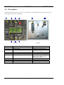
Microair Avionics Pty Ltd
Airport Drive
Bundaberg
Queensland 4670
Australia
Tel:
+61 7 41 553048
Fax: +61 7 41 553049
e-mail: [email protected]
Microair Avionics
M760 Transceiver
Installation & User Manual
About This Document
This manual describes the various installation configurations
available for the Microair M760 Transceiver. The
Transceiver’s controls and design features are described and
illustrated.
Microair reserves the right to amend this manual as required,
to reflect any enhancements or upgrades to the M760
Transceiver.
© Microair Avionics Pty Ltd
MICROAIR M760 ACCESSORIES
Wiring Harness
Boom Microphone
Speaker Box
Dynamic Microphone Amplifier
CURRENT REVISION STATUS
Revision
K
L
M
N
Date
31/01/2000
18/11/2001
04/10/2002
08/12/03
760 install & user manual ver N.doc
Change
Initial release
Additional install data and wiring diagram added
Additional wiring diagram added
Updated for revision N
Page 2 of 24
8th December 2003
Microair Avionics
M760 Transceiver
Installation & User Manual
Table of Contents
1.0
Introduction
4
2.0
Unpacking
4
2.1
2.2
2.3
User / Install Manual
Warranty Card
Authorised Release Certificate
4
4
4
3.0
Description
5
4.0
Installation
6
4.1
4.2
4.3
4.4
Physical Installation
Electrical Installation
Coax Termination
Antenna
6
7
8
8
4.4.1
Metal Skin Airframes
9
4.4.2
Non-Metal Skin Airframes
9
4.5
4.6
4.7
4.8
4.9
Backlighting
Power Savings
Microphone
Speaker
Intercom
9
9
10
10
11
4.9.1
Sidetone
11
4.9.2
Mic Gain
11
5.0
5.1
5.2
5.3
5.4
Control Functions
12
Priority Switch
Volume / Squelch Knob
Annunciator LED
Mode Switch
12
12
12
13
5.4.1
Toggle mode
13
5.4.2
Memory Mode
13
5.4.3
Program Mode
13
5.4.4
Scan Mode
13
5.5
5.6
Frequency Adjust Knob
Toggle Switch
14
14
6.0
Memory Programming
15
7.0
Operation
16
7.1
Remote Memory Button
16
8.0
Appendix A –Wiring Diagrams
17
9.0
Appendix B - Specifications
21
10.0 Appendix C – Drilling Template
22
11.0 Limited Warranty
23
760 install & user manual ver N.doc
Page 3 of 24
8th December 2003
Microair Avionics
M760 Transceiver
Installation & User Manual
1.0 Introduction
Thank you for purchasing this Microair product. The M760 is a 760 channel VHF aircraft transceiver, packaged
to fit a standard 57mm (2 ¼”) instrument hole. The M760 has been produced in accordance with CASA APMA
approval E2000-004.
2.0 Unpacking
The M760 is boxed in polystyrene for physical protection, and wrapped in an anti-static bag for electrical
protection. Once the box is opened and the radio unwrapped, the owner is responsible for physical and
electrical protection.
Enclosed with the radio are: User / Install Manual
Warranty Card
CASA form 1 – release certificate
DB15 solder plug and backshell
2.1 User / Install Manual
Please read this manual completely before attempting to install or operate this radio. There are several
installation options you may wish to consider, which are clearly laid out in the installation section.
The M760 has all of the basic radio operations, and many other management and programming options,
which are described in the operation and memory sections of this manual.
2.2 Warranty Card
Please complete the warranty card and post it back to Microair. The obvious benefit is to ensure your 12
month warranty is recognised (refer to the limited liability warranty statement on the back cover of this
manual).
Another benefit of returning the card is, it allows Microair to send you service data directly, should the
need arise. Microair monitors all feedback on its products. Should the need arise to alert or advise
customers of a potential problem, good installation ideas, or things to avoid, Microair will despatch a
service bulletin to the customer address list on file.
2.3 Authorised Release Certificate
The CASA form 1 – release note is an internationally recognised document which clearly identifies the
part/component the form 1 is associated with. Please keep this certificate with the aircraft’s file or log
book.
760 install & user manual ver N.doc
Page 4 of 24
8th December 2003
Microair Avionics
M760 Transceiver
Installation & User Manual
3.0 Description
The M760 VHF Transceiver has a 57mm (2 ¼”) round face to fit a standard small instrument hole. The case is
59mm high x 65mm wide x 135mm long.
Front Face
ITEM
1
2
3
Rear Face
CONTROL
M4 Machine Screw
Priority Switch
Volume / On / Squelch
DESCRIPTION
4
5
6
Receiver / Transmit Annunciator
Mode Switch
Frequency Adjust
7
8
9
10
Toggle Switch
DB15 Connector
BNC Coaxial Connector
LCD Display
760 install & user manual ver N.doc
Momentary push down switch
Click On - Rotate knob for volume
Rotate ring for squelch
Red / Green LED
Momentary push down switch
Rotate for MHZ adjust
Push briefly to change to KHZ
Rotate for KHZ adjust
Momentary push down switch
Push in fit with lock nuts
Two lines of eight characters each
Page 5 of 24
8th December 2003
Microair Avionics
M760 Transceiver
Installation & User Manual
4.0 Installation
4.1 Physical Installation
The M760 is very simple to physically install in an aircraft’s instrument panel. Select or cut a 57mm (2
¼”) instrument hole for mounting. Present the M760 to the rear face of this hole. The stepped round face
will insert through the hole, and should appear flush with the front of the instrument panel when correctly
positioned. Rotate the M760 to align the four M4 machine screws.
For installations where the existing instrument panel screw holes are 1/8”, the hole will need to be
enlarged to 5/32” to fit the M4 machine screws.
Insert and tighten all four M4 machine screws. The M760 requires no rear support, the M4 screws
provide all of the physical mounting required.
50 OHM
COAX
BNC CONNECTOR
WIRING HARNESS
NO REAR SUPPORT REQUIRED
DB-15 CONNECTOR
MIC GAIN TRIM POT
SIDETONE TRIM POT
M4 MACHINE SCREWS
57MM (2 1/4") INSTRUMENT HOLE
MICROAIR MA-760
PANEL INSTALLATION
The M760 should be located in the aircraft within view of the pilot seated in the pilot-in-command
position, and afford this pilot good access to the front face controls.
Do NOT oversize the mounting holes in the front face of the radio,
to an imperial size. Drilling will damage internal components.
Do NOT replace the M4 machine screws supplied with the radio
with longer screws. Over-length screws will touch or even crush
internal components and cause damage.
Either of these actions will void the warranty
760 install & user manual ver N.doc
Page 6 of 24
8th December 2003
Microair Avionics
M760 Transceiver
Installation & User Manual
4.2 Electrical Installation
Microair recommends the use of the wiring in the table below for the various parts of the radio harness:
Line
Power & Ground
Intercom
PTT
Memory
Signal Ground
Speaker
Microphone
Headphone
Aerial
Wire
Tefzel 18 awg wire
Tefzel 22 awg wire
Tefzel 22 awg wire
Tefzel 22 awg wire
Tefzel 22 awg wire
Tefzel 22 awg single core shielded
Tefzel 22 awg single core shielded
Tefzel 22 awg single core shielded
RG58C/U 50 ohm Coaxial Cable
All wiring is connected by soldering to the DB15 connector.
Strip the insulation back 2mm (1/16”), and “tin” the exposed conductor with solder. Slide a 5mm length
of 3.2mm (1/16”) heatshrink tubing over the end of the wire. After checking the wiring diagram for the
correct pin number, push the “tinned” end into the terminal, and solder into place. Check the soldered
joint has been made, by gently pulling on the wire. Slide the heatshrink tubing down over the soldered
pin, to completely cover the conductor.
“Tinned” wire
Soldered with heatshrink
Locking bolts tightened
Cover the soldered joints with the grey plastic backshells. Ensure that the locking bolts are in place
before closing the backshells. Connect to the rear of the radio with a push fit, and secure the locking bolts
(top and bottom).
The M760 can be wired in several different configurations, to suit the various needs. The wiring
diagrams located in Appendix A cover the most commonly used variations.
Microair recommends the use of its pre-wired
M760 harness.
The harness is available from Microair, and
comes complete with all switches, sockets,
buttons, and mounting hardware.
Separate lines have been wired for Pilot and Copilot:
•
Headphone
•
Microphone
•
PTT
•
Remote Memory
•
Intercom ON/OFF
760 install & user manual ver N.doc
Page 7 of 24
8th December 2003
Microair Avionics
M760 Transceiver
Installation & User Manual
4.3 Coax Termination
The coax is cut to length and terminated in a BNC connector. Soldered or crimp type connectors are
preferred to the solderless variety, as they have lower signal loss and better shielding.
6.5mm
(1/4")
Step 1
3.2mm
(1/8")
1.6mm (1/16")
Step 2
Step 3
Step 4
BNC Termination
Microair recommends using only soldered or crimped BNC connectors. Solderless BNC connectors are
NOT recommended, as their performance is not high enough for VHF transmissions.
4.4 Antenna
For certified aircraft the M760 should only be operated with a TSO compliant antenna. The antenna may
be ¼ wave whip or ½ wave dipole, using 50ohm coaxial cable and a BNC connector for connection. The
VSWR should ideally be less than 2:1 across the 118.000MHz to 136.975MHz airband.
For non-certified aircraft using a non-TSO compliant antenna, the VSWR must be checked to ensure the
ratio does NOT exceed 3:1 across the 118.000MHz to 136.975Mhz airband. The M760 will tolerate a
VSWR of 5:1 without injury to the transceiver, but the performance is severely deteriorated.
Do not use the stubbie “rubber duckie” antennas meant for use with handheld radios.
Where the cable length for the coaxial cable exceeds 15m (45 feet), the RG-58C/U cable should be
replaced with RG-213/U cable. At 15m, the RG-58C/U has approx 3dB loss (50% power), where the
RG-213/U has only 1.5dB (75% power). For situations where maximum radio output power is essential,
use only RG-213/U
760 install & user manual ver N.doc
Page 8 of 24
8th December 2003
Microair Avionics
M760 Transceiver
Installation & User Manual
4.4.1 Metal Skin Airframes
For metal skin aircraft a ¼ wave whip is the easiest antenna to fit. Ensure that the antenna base and the
coax shield are firmly grounded to the skin of the airframe, on the inside of the aircraft. Ensure that any
anti-corrosion product, which may be used to seal the exterior surface, does not isolate the antenna base
from the airframe. For best performance the whip should be straight and vertical, when mounted on the
airframe.
4.4.2 Non-Metal Skin Airframes
For non-metal airframes, a ¼ wave whip may still be used, but a ground plane must be installed, on the
inside face of the aircraft skin. The ground plane should ideally be circular, and have a diameter of half
the height of the whip. The ground plane should be fabricated from a lightweight metal, eg thin
aluminium sheet, or adhesive foil tape. For best performance the ground plane should be flat and
horizontal, when mounted on the airframe.
An alternative antenna for non-metal airframes is the Ground Plane independent dipole. This antenna is
physically similar to the ¼ wave whip, but has a small stubbie antenna pointing downwards from the
antenna base. The stubbie section of the antenna takes the place of the ground plane, and simplifies
installation.
Beware of fabric surfaces with silver dope finishes. The silver dope is a conductive surface, and with
screen antennas which are mounted internally.
4.5 Backlighting
The backlighting is activated, by taking input supply voltage to pin 8. This line can be individually
switched outside the DB15 connector to enable the backlighting to be turned off.
If the backlighting is wired but not switched, the backlighting will come on when the master switch is
turned on. The aircraft may be started with the radio off, but with the backlighting active, without the
possibility of injury to the radio.
The backlighting line from pin 8 may be taken to a dimmer. The backlighting consists of 4 LED’s behind
the LCD display which operate on 1-14 volts. The backlighting cannot be seen below 3 volts.
4.6 Power Savings
For installations, operating from a battery only, Microair recommends saving battery power by NOT
wiring the backlighting – do NOT wire pin 8. The backlighting will draw an additional 80mA of power.
This nearly doubles the standby power demand.
Not connecting the backlighting can effectively double the running time on your battery.
The operator should remember that the minimum operating voltage is 10 volts. This is the loaded voltage
(ie the voltage when the radio is transmitting). For battery operators, check the battery voltage level, then
press the PTT briefly to note the voltage drop. If the voltage dips by more than 0.5 volts, change the
battery before flying.
760 install & user manual ver N.doc
Page 9 of 24
8th December 2003
Microair Avionics
M760 Transceiver
Installation & User Manual
4.7 Microphone
The M760 can be operated with an Electret Insert or Amplified Dynamic microphone. These alternatives
cover most aviation headsets and hand microphones.
When the PTT is pressed both microphones are live. To reduce background noise, the M760 can be
installed with relays across the mic lines and the PTT line, to allow on one microphone at a time to
operate (refer appendix A). This reduces background noise when transmitting.
For operators wanting to use a dynamic microphone, a mic amplifier must be used. Microair recommends
the installation of the Microair MD-01a amplifier. This amp is compatible with 150-600 ohm dynamic
microphones.
LINES TO DYNAMIC MIC
OR MIC JACK
CONNECTOR (MIC END)
MIC SIGNAL LINE
(7-9 VOLTS)
MD-01a
CONNECTOR (RADIO END)
CRIMP TERMINALS
GROUND
4.8 Speaker
Microair recommends using a speaker of 4 ohms
impedance, rated at a minimum of 5 watts.
Microair recommends the SP01 Box Speaker.
The SP01 has a durable thick film plastic cone of
4 ohms, and is rated at 5 watts. The SP01 is fitted
with a mounting bracket, and is supplied with
clips and screws.
Check your speaker choice by ensuring the audio
is clear up to at full volume.
760 install & user manual ver N.doc
Page 10 of 24
8th December 2003
Microair Avionics
M760 Transceiver
Installation & User Manual
4.9 Intercom
The M760 utilises the sidetone facility, to produce a “hot mic” intercom. This means the mic’s are “live”
at all times, to the pre-set levels of the sidetone and the mic gain. Both pilot and co-pilot can speak and
be heard at all times. Hot mic operation is not a VOX system where the mic’s only come on when a preset noise threshold is reached (ie when you speak the mic comes on).
It is therefore important to ensure that the sidetone and mic gain are set to the correct levels, so that the
mic’s do not pick up large amounts of ambient noise. The sidetone and mic gain are pre-set in the factory
to levels which should suit most general aviation needs. Microair recommends that mic-muffs be fitted to
all microphones, as a principal way of reducing the pick up of ambient noise.
The intercom facility is enabled by grounding pin 5. This can be done via a switch to turn the intercom
on and off. If, after installing, and trying the intercom, there is too much background (ambient) noise, reset the sidetone and the mic gain in the following way:
4.9.1 Sidetone
1.
2.
3.
4.
5.
Connect headset(s) to the radio
Turn down headset volume to minimum
Close sidetone trim pot by turning fully counter clockwise
Speak into microphone with a constant “Laaaa” tone, and increase the sidetone by turning clockwise
Stop when good volume is heard. Test this level with the headset volume to maximum
4.9.2 Mic Gain
1.
2.
3.
4.
5.
Connect headset(s) to the radio
Start engine, and listen to ambient noise
If ambient noise is too high, turn down mic gain with a SMALL counter clockwise turn
When the noise is down to an acceptable level, make a test transmission to another radio
If the audio quality of the transmission is too weak, the mic gain must be increased
Please refer to the figure below to see how the trim pots are adjusted. The trim pots have a total
movement of only 270 degrees (3/4 turn). The heads of the trim pots are plastic, and can be distorted or
broken off unless adjusted with great care. A small straight blade screwdriver with an insulated shaft is
required. Ensure the radio is turned off before punching the hole under the black dot, and probing for the
slot in the head of the trim pot. Once the screwdriver is engaged on the trim pot, the radio can be turned
on, and the adjustment made.
Mod status
1
2
3
4
5
6
7
Caution
No user parts inside
Do not open case
Do not make any unauthorised
adjustments
Reverse polarity will cause
damage and void warranty
8
9 10
Mic Gain
Sidetone
STRAIGHT BLADE SCREWDRIVER
WITH INSULATED SHAFT
INCREASE
DECREASE
NOTE
TOTAL TRIMPOT MOVEMENT IS 270 DEGREES ROTATION
MICROAIR MA-760
TRIMPOT ADJUSTMENT
Do not attempt to adjust the modulation or power output. These
adjustments can only be set correctly by a qualified technician.
Adjustment of the power output or modulation by anyone other
than Microair or their approved agent will void the warranty.
760 install & user manual ver N.doc
Page 11 of 24
8th December 2003
Microair Avionics
M760 Transceiver
Installation & User Manual
5.0 Control Functions
5.1 Priority Switch
The priority switch is a push down switch. When pushed down briefly, the radio will go into memory
mode, and select the frequency stored in memory 25. Memory 25 should be considered the priority
channel, which the user can quickly select when required. Memory 25 must be programmed for the
priority switch to operate. Memory 25 is set at the factory as the international distress frequency
121.500MHz. Memory 25 can be programmed the same way as any of the other channels (refer memory
programming), hence the factory default can be edited.
5.2 Volume / Squelch Knob
The M760 is turned on, by rotating the volume knob. A positive “click” is heard and felt at the start of
the rotation to indicate the on/off position. The volume is increased by rotating the knob clockwise, and
decreased by rotating counter clockwise.
The squelch is adjusted by rotating the ring behind the volume knob. There is no automatic level set for
the squelch, however the ring affords a large manual adjustment to suit all situations. Rotate the ring
clockwise to increase the squelch threshold, and counter clockwise to lower the threshold. When the
squelch is “broken” (ie the static hiss can be heard), the annunciator LED lights green.
Note:
This does NOT mean you are receiving a signal!
5.3 Annunciator LED
The LED operates red or green, and indicates the following states:
Clear (off)
Radio is squelched above the threshold, and is not receiving a signal
Green
Squelch is broken or a signal is received
Red
Radio is transmitting
Flashing Red
Radio has transmitted for over 40 seconds (warning)
The flashing red signal may draw the user’s attention to the fact that the aircraft may have a stuck PTT
button! Transmissions in excess of 30 seconds should be avoided.
760 install & user manual ver N.doc
Page 12 of 24
8th December 2003
Microair Avionics
M760 Transceiver
Installation & User Manual
5.4 Mode Switch
The mode switch is a push down switch. When pushed down briefly the radio will step to the next
operating mode. The M760 has four operating modes:
5.4.1 Toggle mode
The display shows the active or in use frequency on the top line. The standby frequency is
displayed on the bottom line.
5.4.2 Memory Mode
The top line displays the memory or MEM number, and the lower line displays the frequency for
that memory. The displayed memory becomes the frequency the moment it is displayed. The user
can scroll through the programmed memories by rotating the frequency adjust knob, or by
pressing the remote memory button.
5.4.3 Program Mode
The MEM is replaced with PROG on the top line. The frequency stored in each memory can be
set, changed, or cleared in this mode (refer memory programming).
5.4.4 Scan Mode
By holding down the toggle switch for 3 seconds, the M760 goes into scan mode. The
programmed memories are cycled quickly across the display. The M760 checks each memory in
turn for any signal. If there is no signal the radio moves to the next programmed memory. When a
signal is detected, the scan locks to that memory to receive the signal. This memory is held for 10
seconds after the signal finishes to afford the user an opportunity to reply on that memory channel.
The user can stop the scan operation by pressing down briefly the toggle key, or the PTT button.
760 install & user manual ver N.doc
Page 13 of 24
8th December 2003
Microair Avionics
M760 Transceiver
Installation & User Manual
5.5 Frequency Adjust Knob
The standby frequency can be changed by scrolling the frequency adjust knob. Rotate knob to scroll the
MHz half of the standby frequency. Press the knob in briefly to move the cursor to the KHz half of the
standby frequency. Rotate the knob again to scroll the KHz. The cursor will remain where it was lasted
toggled.
Only the standby frequency can be changed directly, the active frequency cannot be directly altered by
the frequency adjust knob.
Cursor
MHz
KHz
5.6 Toggle Switch
The toggle switch is a push down switch. When pushed down briefly, the active and standby frequencies
exchange places. Hold the toggle key down for 3 seconds to activate the scan function.
760 install & user manual ver N.doc
Page 14 of 24
8th December 2003
Microair Avionics
M760 Transceiver
Installation & User Manual
6.0 Memory Programming
The M760 has 25 programmable memories, for storing commonly used frequencies.
Use the mode switch to move the display to the program mode. The word PROG will appear on the top
line, with the memory number on the right hand side. On the lower line is the currently stored frequency
in that memory.
The cursor can be cycled through the MHz, KHz, and memory number by pressing the frequency adjust
knob.
Move the cursor to the memory number and select the memory number for programming, by rotating the
frequency adjust knob.
Press the frequency adjust knob to move to the MHz section. Rotate the frequency adjust knob to scroll
to the desired value.
Press the frequency adjust knob to move to the KHz section. Rotate the frequency adjust knob to scroll to
the desired value.
Cycle cursor between program number, MHz, and
KHz, by pressing the frequency adjust knob
inwards briefly. Rotate the frequency adjust knob
to change value.
With the memory number, and frequency set to the correct values, press down the toggle switch briefly.
The word STORE appears briefly on the top line.
To clear a memory, scroll to the desired memory, and press down the priority switch briefly. The word
CLEAR appears on the top line.
The user can now move to another memory for programming. Press the frequency adjust knob to move
the cursor back to the memory number, and scroll to next memory for programming.
When all programming is complete, press the mode switch to move on from the program mode, back to
the active/standby toggle display.
When operating in memory mode, the programmed channels can be scrolled through, by rotating the
frequency adjust knob, or by pressing the remote memory button. Only programmed memories are
displayed.
Operating the priority switch in either toggle or memory mode will move the M760 to memory 25. The
user should consider carefully what frequency to program in memory 25. The factory default is the
distress frequency 121.500MHz.
760 install & user manual ver N.doc
Page 15 of 24
8th December 2003
Microair Avionics
M760 Transceiver
Installation & User Manual
7.0 Operation
The M760 should always be turned off, before starting the aircraft to protect the radio from transient
voltages. After starting, the radio can be turned on, and the squelch adjusted so the static hiss can be
heard through the headphones. The LED annunciator will light green while the hiss is heard. Use the hiss
tone to adjust the volume to an appropriate level. With the volume set, turn the squelch ring to break the
squelch and eliminate the hiss. The LED annunciator light will go clear.
It may be necessary to readjust the squelch with the engine at full power, as the ignition noise increases
dramatically.
The intercom volume is pre-set, and not affected by the volume knob (refer Intercom section on page10).
The M760 can now be adjusted to the correct active and standby frequencies, by scrolling and pressing
the frequency adjust knob.
The M760 will transmit when the PTT button is held down. The LED annunciator will light red. When
transmitting the user will hear themselves speaking through their own headphones via the sidetone
system. If the transmission lasts longer than 40 seconds, either because you have a lot to say, or because
the PTT has stuck, the LED annunciator will flash red. When this happens, check the PTT immediately.
If you find no obvious fault, turn the radio off, and then on again. If the LED is still red, turn the radio off
and leave it off.
7.1 Remote Memory Button
If fitted at installation, the remote memory button will allow the user to toggle (exchange) the active and
standby frequencies. The remote memory button is typically mounted next to the PTT on the stick.
If the user elects to operate in memory mode, the remote memory button will step through the
programmed memories.
If the Remote memory button is held down for 5 seconds, the M760 will go into scan mode, and
automatically scroll through the programmed memories, searching for a signal.
To terminate the scan operation, the PTT is pressed briefly.
The remote memory button is highly recommended. It allows the
user to be able to keep hands on the controls during flight, while
changing channels or scanning.
760 install & user manual ver N.doc
Page 16 of 24
8th December 2003
Microair Avionics
M760 Transceiver
Installation & User Manual
8.0 Appendix A –Wiring Diagrams
Standard Wiring
Includes remote memory, intercom, and backlighting switches,
along with cabin speaker.
PTT Operation
Include a mode switch to allow the PTT button to be used for either
transmit or intercom
PTT Relay Operation
Includes the use of two relays across both mic ines and the PTT line
to allow only one microphone at a time to operate
760 install & user manual ver N.doc
Page 17 of 24
8th December 2003
Microair Avionics
760 install & user manual ver N.doc
M760 Transceiver
Page 18 of 24
Installation & User Manual
8th December 2003
Microair Avionics
760 install & user manual ver N.doc
M760 Transceiver
Page 19 of 24
Installation & User Manual
8th December 2003
Microair Avionics
760 install & user manual ver N.doc
M760 Transceiver
Page 20 of 24
Installation & User Manual
8th December 2003
Microair Avionic
M760 Transceiver
Installation & User Manual
9.0 Appendix B - Specifications
Specifications
Radio Type
Amplitude Modulation (AM) Aircraft Transceiver
Channels
760 channels, 25KHz spacing
Frequency Selection
VFO dial
Frequency Display
2 line alpha/numeric LCD display (with backlighting)
Frequency control
PLL frequency synthesis, which is microprocessor controlled
Memory is store in non-volatile EPROM
Memories
25 programmable memories with scan function
Scan Function
On programmed memories only – scan rate 3 memories/second
Power consumption
Receive (no signal)
Transmit
Input Voltage
10 – 16 Volts Warning damage will occur above 16 Volts
Power output
4 watts (nominal)
VSWR Tolerance
< 5:1
Receiver sensitivity
12dB for 1.0 uV 30% modulation (KHz audio)
Receiver Selectivity
-70dB
Squelch Threshold
0.5uV (full squelch range 0.5-3.5uV)
Speaker volume output
Nominal 4 watts output to 4 ohms
Headset volume output
Nominal 100milli-watts output to 600 ohms
Temperature range
-30 - +60 degrees Celsius
Stability
+/- 3.00ppm
Dimensions
W-65mm H-59mm D-135mm (plus 35mm for harness)
W-2.6”
H-2.3”
D-5.3”
(plus 1.5” for harness)
Exposed dial face
57mm diameter
2 ¼” diameter
Weight
400 grams
19.4 ounces
760 install & user manual ver N.doc
118.000 – 136.975MHz
86 mA
1.6 A
Page 21 of 24
8th December 2003
Microair Avionic
M760 Transceiver
Installation & User Manual
10.0 Appendix C – Drilling Template
Drilling Template
760 install & user manual ver N.doc
Page 22 of 24
8th December 2003
Microair Avionic
M760 Transceiver
Installation & User Manual
11.0 Limited Warranty
Microair Avionics Pty Ltd warrants this product to be free from defects in
materials and workmanship for 1 year from the date of purchase or the
minimum period described by applicable consumer law.
If the unit is installed by an organisation which holds an avionics
installation approval from the local Civil Aviation Authority, and that
organisation has co-signed and dated the warranty card, the warranty
period shall be deemed to commence from the date of installation.
The customer shall be responsible for any transportation costs for return of this product to Microair Pty Ltd.
This warranty does not cover failures due to abuse, misuse, accident, unauthorized alteration, or repairs carried
out by parties other than Microair or an approved Microair service centre. This warranty does not cover failures
where the product has not been installed or operated, in accordance with the provisions of the User and
Installation manual(s).
It shall be at Microair Pty Ltd’s sole discretion to decide if a defect is a result of material or workmanship
failure.
THE WARRANTIES AND REMEDIES CONTAINED HEREIN ARE EXCLUSIVE AND IN LIEU
OF ALL OTHER WARRANTIES EXPRESSED OR IMPLIED, INCLUDING ANY LIABILITY
ARISING UNDER WARRANTY OF MERCHANTABILITY OR FITNESS FOR A PARTICULAR
PURPOSE, STATUARY OR OTHERWISE. THIS WARRANTY GIVES YOU SPECIFIC LEGAL
RIGHTS, WHICH MAY VARY FROM STATE TO STATE, AND COUNTRY TO COUNTRY.
IN NO EVENT SHALL MICROAIR AVIONICS PTY LTD BE LIABLE FOR ANY INCIDENTAL,
SPECIAL, INDIRECT OR CONSEQUENTIAL DAMAGES, WHETHER RESULTING FROM
THE USE, MISUSE OR INABILITY TO USE THIS PRODUCT OR FROM DEFECTS IN THE
PRODUCT.
To obtain warranty service, CALL the Microair Avionics Support line in Australia:
Phone:
Fax:
Email:
++ 61 7 41 553048
++ 61 7 41 553049
[email protected]
Contact Microair Avionics for instruction on the return of product for service or repair. Please ensure that you
are able to supply the date of purchase, product type reference, serial number, method of return and date of
return. All product returning to Microair Avionics should be marked clearly:
“PRODUCT RETURNING TO COUNTRY OF ORIGIN, FOR WARRANTY SERVICE /REPAIR,
AND WILL BE RE-EXPORTED”
Address to either:
Microair Avionics Pty Ltd
P O Box 5532
Bundaberg West
Queensland 4670
Australia
Microair Avionics Pty Ltd
Airport Drive
Bundaberg West
Queensland 4670
Australia
Microair may at it discretion, refer product returns for repair or service, to a service facility closest to you.
Microair Avionics Pty Ltd reserves the right to repair or replace the unit or software or offer a full refund of the
purchase price at it’s sole discretion.
SUCH REMEDY SHALL BE YOUR SOLE AND EXCLUSIVE REMEDY FOR ANY BREACH
OF WARRANTY.
760 install & user manual ver N.doc
Page 23 of 24
8th December 2003
Supplied by: