1
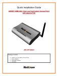
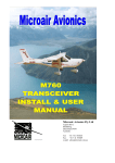
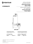
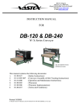
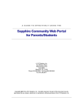
AirNet
CAN to Ethernet Adapter
Setup Manual
Micro Air Corporation
124 Route 526
Allentown NJ 08501
Phone (609) 259-2636
www.Microair.net
Fax
(609) 259-6601
Note to installers:
These manual requires making changes to the network router and obtaining a DDNS
service. Understanding this manual and the user manual for the router used are required
to successfully install this device. Please read and understand all sections of this manual
before proceeding with installation.
Making the wired connections:
1. Install all controls and associated hardware per manufacturers guidelines.
2. Install the CAN to Ethernet adapter in a secure location with access to a wired
Ethernet connection to a router. Set jumper P4 on the AirNet Can to Ethernet
adapter for the input voltage as shown in Figure 1. Connect term1 and term2 on
the AirNet CAN to Ethernet adapter to the power source but do not apply power.
Figure 1:
208-240 VAC
120 VAC
3. Wire the controls as shown in Figure 2 from one control to the next with
terminators (CT) installed only on the last control on each end of the system. Wire
polarity must be observed. Only two terminators are permitted in the system.
CAN cable must be SAE J1939 compatible and wired from one control to the next
without any star type wiring configurations. Any other wiring method will not
work properly.
Figure 2
4. Configure the CAN bus group and unit ID’s for each control. See the section on
“Organizing ID’s in the CAN system” for guidelines on correctly setting up the
ID numbers. See the controls manual for specific details on setting the address in
each control
©2015 Microair Corp
2
Rev: 1.02
5. Plug in the Ethernet cable from the router to the AirNet CAN to Ethernet adapter.
6. Power all the controls in the system but do not power the AirNet CAN to Ethernet
adapter until all the controls have been powered. If you powered the adapter first,
simply remove power for 10 seconds, and then reapply power.
Wiring FAQ
Power was applied before the wiring was completed. What do I do?
The first time the network is powered, the AirNet CAN to Ethernet adapter
collects information about the system. If all the controls do not show up after
configuration, just remove power, wait 10 seconds, and reapply power.
Power was removed and reapplied but all the controls still do not show up after
configuration.
Verify the setup rules in “Organizing Id’s in the CAN system. You may have 2 or
more devices with the same unit ID.
Why do no Controls show up after configuration?
Only wiring or power issues can cause no controls to show up in the iPhone
AirNet5i app once configured. Be sure the system is wired correctly and power is applied
to all the controls in the system. Remove power from the AirNet CAN to Ethernet adapter
for 10 seconds and reapply power.
©2015 Microair Corp
3
Rev: 1.02
Configure the AirNet CAN to Ethernet adapter:
Finding the AirNet CAN to Ethernet adapter on the network:
To configure the adapter, you will need to determine the network address for the
adapter. Find the MAC address printed on the AirNet Can to Ethernet adapter case. Log
into your router and browse to the DHCP client table (consult your routers documentation
to determine how to access the DHCP table). Compare this address to addresses listed in
the routers DHCP client table to the address on the AirNet CAN to Ethernet adapter and
write down the IP address assigned to the adapter.-Reserving addresses in the router:
If your router has the capacity to reserve addresses, reserve the address for the
AirNet Can to Ethernet adapter in the DHCP table. If your router does not have the
ability to reserve addresses, you can select an address outside of the DHCP address range
to set as a static address for the AirNet CAN to Ethernet adapter.
Log into the adapter:
Once you know the address, use your phone, laptop, or PC
and browse to the address using a web browser. For example if
your address is 192.168.1.15, you would put
192.168.1.15/setup.htm in the browsers address bar. The page will
prompt you for a user name and password. The default user name
is “admin” and the password is “admin”. The screen shown in
Figure 3 will be similar to what you see after entering the
password.
Configure the address and DHCP:
If you reserved the IP address in your router, no further
setup is necessary and you can skip to the next section.
If you did not reserve an address, click IP address and set an available address
outside the routers DHCP range. (See Configure FAQ) Click “Set” to store the new
address. Click the DHCP option, uncheck the enabled box, and click set. DHCP will now
indicate “OFF” as shown in Figure 3. Remove power from the AirNet CAN to Ethernet
adapter. Wait 10 seconds and reapply power. The address will now be changed to the
new address. To access the setup page again, enter the new address in your browser along
with /setup.htm as shown in “Log into the adapter”.
©2015 Microair Corp
4
Rev: 1.02
Change your admin password:
Your admin password can be changed so no users
may make changes to your settings. To change the
password, press “Change Admin Password” then enter a
new password (up to 20 characters) in the text window at
the top and press “Save”. Be sure to remove the word
“Password” from the text box. It is only there as a prompt.
Enter the IP address in the iPhone®™ AirNet5i
application:
Once the adapter is configured, use the network IP address as the local address in
the iPhone™ AirNet5i application available in the iTunes™ store. This app can then be
used to control any supported device on the CAN bus when the phone or tablet is
connected to the routers local network. For access outside your local network, follow the
instructions in the section “Setting up your router for internet access” after completing
this section.
Configure FAQ
How do I reserve an address?
Consult the manual for your router for reserving an IP address. The address
reservation is usually under the DHCP server selection for enabling the DHCP server.
My router does not support reserving an address. What do I do?
Look in your routers manual for enabling the DHCP server. When DHCP is
enabled there is a range of addresses listed that the router will give out to connected
devices. If the range is set for x.x.x.50 to x.x.x.100 then the router will serve only
addresses from 50 to 100. Set the static address when you log into the adapter for an
address from 2 to 49 or 101 to 254. Only change the last number after the decimal point.
For example, if your range if 192.168.1.50 to 192.168.1.150 then you can enter
192.168.1.20 as long as no other devices in the DHCP list or on the system have that
address. This will be your static network address. You will need to power down the
adapter and restore power to make the change effective. Put the new static network
address in the browser to reconnect with the adapter.
©2015 Microair Corp
5
Rev: 1.02
Setting up your router for internet access:
The following instructions are used when an internet connection to the router is
available. These steps permit the iPhone™ AirNet5i application to control the supported
devices from anywhere. The adapter must be configured before completing these steps.
See “Configuring the adapter” for details.
Step 1: Set up a router or PC with a DDNS service.
Step 2: Enable port forwarding in the router from an external port (over 1024 for
most ISP’s) to the IP you set up from “Configuring your adapter”. The
external port must forward traffic to port 80.
Step 3: Enter the web address and port in the iPhone™ AirNet5i application.
Setting up FAQ
What’s a DDNS service?
A DDNS service is a paid service that tracks your local IP address so that you are
visible on the internet from anywhere. This means if your vessel moves from one port to
another, access will be available whenever the internet is connected.
How do I select a DDNS service?
The best way is to select a service that is compatible with your router. Most
routers allow one or more different DDNS providers. Follow your routers instructions for
enabling a DDNS service and select a provider from the available list. Go to the
provider’s website and follow the instructions for creating the service. When you sign up
for the service, you will select a web address and password that you will enter into the
router to complete the DDNS setup.
If a service is used that your router does not support, you will need a DDNS client
installed on a PC or network device that runs all the time. The client is just a PC program
that you run and setup just like the setup in the router.
What is “Port Forwarding” and how do I enable it?
You will need to enable port forwarding to allow AirNet5i to contact your CAN
to Ethernet adapter from outside your local network. Port forwarding allows requests
from outside your network to reach devices inside the network. To enable it, open to your
routers setup page and find the page for port forwarding, usually under the “Application
and Gaming” or “Forwarding” tab. Add an entry for the IP address using the “From” or
“Service” port as some number between 1024 and 65000 and the “To” or “Internal” port
as port 80. Set the protocol selection to “All”.
©2015 Microair Corp
6
Rev: 1.02
What address do I enter in the iPhone application?
If you chose, for example, a noip.com address of MyWonderfulYacht.noip.me as
your DDNS address and you selected port 12345 as your port, you would enter
MyWonderfulYacht.noip.me:12345 as the global address in the iPhone™ AirNet 5i
application. The app will automatically connect to the appropriate address when the app
is started.
©2015 Microair Corp
7
Rev: 1.02
Organizing IDs in the CAN system
Controls are addressed on the CAN bus by assigning group ID and unit ID
numbers to each control in the system.
System example:
Control
Area 1, Air handler
Area 2, Air handler 1
Area 2, Air handler 2
Area 3, DX system
Ice maker
Area 4 Air handler 1
Area 4 Air handler 2
Area 4 Air handler 3
Hydromatic 1
Hydromatic 2
Hydromatic 3
Hydromatic 4
Pump relay
Unit
1
2
3
4
5
13
14
15
131
132
133
134
139
Group
1
2
3
4
5
16*
16*
16*
131
131
131
131
131
Master (Slave 1)
Slave 2
Slave 3
Slave 4
System pump for Hydromatic
Rule 1: All controls must have unique unit IDs.
Rule 2: All controls that independently service an area should have the same
group ID as their unit ID. See units 1 to 5 above.
Rule 3: Controls that service a common area may have the same group ID. See
units 13, 14, and 15 above.
Rule 4: Each Hydromatic control in a system must have the same group ID.
Rule 5: The Hydromatic master must have the same unit and group ID.
Rule 6: Each Hydromatic slave in the system must have the next numerically
higher unit ID. See units 131 to 134 above.
Note: Controls are identified to connected computers by serial number. Additionally
some controls require entering the serial number during configuration. When installing
controls, the serial numbers of each control and its location should be recorded.
*Some controls offer a zoning feature that allows one control to command other controls
in the same group when the group ID and unit ID are set for the same value. User
manuals will include details if this feature is available.
©2015 Microair Corp
8
Rev: 1.02
Reset connection settings:
Two small holes by the Ethernet connection provide access to the reset switches.
Resetting the DHCP and static address:
The switch closest to the CAN connector enables the DHCP server and clears the
static IP setting. This is useful if you move the adapter to a new router with a different net
address. Press and hold this switch for at least 10 seconds to reset the server to the factory
connection settings.
Resetting the admin password:
The switch furthest from the CAN connector resets the admin password. Press
and hold this switch for at least 10 seconds to reset the password and user name to
“admin”.
COPYRIGHT © 2015 Micro Air Corporation, All Rights Reserved
No part of this publication may be reproduced, translated, stored in a retrieval system, or
transmitted in any form or by any means electronic, mechanical, photocopying, recording or
otherwise without prior written consent by Micro Air Corporation.
Every precaution has been taken in the preparation of this manual to insure its accuracy.
However, Micro Air Corporation assumes no responsibility for errors and omissions. Neither
is any liability assumed nor implied for damages resulting from the use or misuse of this
product and information contained herein.
©2015 Microair Corp
9
Rev: 1.02