1
2
IO.WW-45.01(ENG)
1. GENERAL CHARACTERISTICS
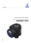
The display WW-45 designed to co-operate with any device with the output signal of
4...20mA and equipped on its output with a standard DIN 43650 connector joint.
The typical application of the display is the addition of a local indicator to the remote
pressure or pressure difference measurement.
The WW-45 has a configurable range of indication between –1999 and 9999, it is
equipped with a LED display (red) with the digits 7.62mm high. It does not require
external power supply. It is equipped with a configurable two-mode output of the open
collector type, as a standard.
2. TECHNICAL DATA
Display error
Input signal
Voltage drop
Ambient temperature
Degree of protection of the housing
Max. current of the two-mode output
0,2% ± 1 digit
4...20mA (generated by voltage max.36V)
max.6V
0...70°C
IP 65
90mA
3. WAY OF CONNECTING
The display is installed between the plug and the socket of the connector joint. The
whole device is tightened with a clamping screw.
2
mA
(-)
3
R0
1
(+)
Fig. 1. Scheme of the electric leads
Input signal between (1) and (2) (4...20mA, max. 40mA)
Two-mode output – between (-) minus of power and (3)
R0 - internal resistance of the two-mode output
4. CONFIGURATION OF THE DEVICE
4.1. USE OF KEYS:
●
●
●
left key (A) – moving up in the menu as well as increasing the parameter value during
the programming
right key (B) – moving down in the menu as well as decreasing the parameter value
during the programming
the keys (A) and (B) used simultaneously – entering the parameter programming level
as well as confirmation of the displayed parameter