1
FA464DR
64 Transmitter / 16-Output Receiver
Installation Instructions
02039F
Document revision history / Notes
Rev. Level
Description
Date
B
Create F:\Eng\parts\02039\E02039B.doc from
P:\Master.dox\FA_dox\FA464.doc (pre-ECN)
6/01
C
Create F:\Eng\parts\02039\02039C.doc from
F:\Eng\parts\02039\E02039B.doc (ECN release version)
7/25/01
D
Replace ISO logo
7/25/01
E
Revise per ECN 2259
10/24/02
F
Add wire gauge p. 4; delete FA200/FA200W p.12
11/21/03
Important Notes
nThis product is designed to be installed and maintained by professional
security technicians.
nUnless specifically noted, Inovonics products are intended for indoor use.
This receiver is intended for use with indoor security systems. Use in outdoor
applications may impair performance.
nTest system regularly.
© 1999 Inovonics Wireless Corporation 02039F.DOC LIT-FA464-INSTALL
1
hc:21-Nov-03
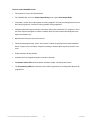
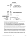
FA464DR
64-Transmitter, 16-Relay Output Receiver
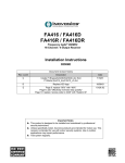
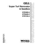
The FA464DR receiver has 16 Form C relay outputs, plus a global fault relay output.
Installers should note that alarm relay terminals are mounted so that normally open or normally closed
terminal positions are side-by-side as shown in Figure 1.
TRANSMITTER NUMBER DISPLAY
TAMPER SWITCH
TRANSMITTER STATUS LEDS
TRANSMITTER PROGRAMMING PORT
TA MPE R
VA LID
DECODE
TAMPE R
DECODE LED
TRANSMITTER
NUMBE R
OUTPUT
DC POWER ONLY
12VDC TYPICAL 18VDC MAX
+
RESE T
ACTIVATE D
REVIEW
STATUS
RESET INPUT
TAMPE RED
2
OUTPUT LEDS 1-16
LOW BATTE RY
3
16
INA CTIVE
4
ADVANCE
DELETE
15
ADVANCE BUTTON
PROGRA MME D
5
DELETE BUTTON
14
6
7
13
8
1
2
ALARM OUTPUTS
1-4 and 13-16
3
4
NOTE:
NORMALLY OPEN TERMINALS
ARE SIDE-BY-SIDE
(8 PLACES)
9
EXTERNAL TAMPER INPUT
POWER INPUT
GND
1
DECODE
NC COM NO NO COM NC NC COM NO NO COM NC
VALID DECODE LED
NC COM NO NO COM NC NC COM NO NO COM NC
REVIEW STATUS BUTTON
TRANSMITTER
PROGRA MMING
WIRING HARNESS
TIE-DOWN HOLES
(2 PLACES)
11
13
14
10
15
16
9
FAULT
GLOBAL FAULT LED
NC COM NO NO COM NC NC COM NO NO COM NC
12
NO COM NC
FA104
PROGRA MME R
FA104 PROGRAMMER PORT
RESE T
RESET BUTTON
POWER
FA116
PROGRA MME R
POWER LED
FA116 PROGRAMMER PORT
5
6
ALARM OUTPUTS
5-8 and 9-12
7
8
FAULT
11
12
NC COM NO NO COM NC NC COM NO NO COM NC
10
FAULT OUTPUT
FA464D
DATA LED
Figure 1
Note: References in this manual to features shown in Figure 1 will be printed in bold italics.
© 1999 Inovonics Wireless Corporation 02039F.DOC LIT-FA464-INSTALL
2
hc:21-Nov-03
Features of the FA464DR include:
x
Full supervision of up to 64 FA transmitters.
x
The FA464DR has 16 Form C Alarm Output Relays, plus a global Fault Output Relay.
x
Transmitter, receiver and output options are factory assigned. They may be changed with the FA116
Executive Programmer or with the FA104 (upgraded C104) programmer.
x
Intelligent global fault output for tamper, low battery and inactive transmitters. For example, if one of
the alarm outputs is assigned to monitor low battery faults, the fault output automatically becomes
tamper and inactive only.
x
Manual and/or electronic reset of the receiver.
x
Factory default programming: "Alarm" and "Inactive" outputs are programmed to follow transmitter
status; "Tamper" and "Low battery" outputs are latching. Latched outputs require the receiver to be
reset.
x
Simple restoral to factory defaults.
x
Automatic exit from programming after 4 minutes of inactivity.
x
Transmitter Status LEDs show transmitter activation, tamper, low battery and inactive.
x
The Programming LED blinks when the point IS NOT programmed, is on steady when the point IS
programmed.
© 1999 Inovonics Wireless Corporation 02039F.DOC LIT-FA464-INSTALL
3
hc:21-Nov-03
Technical Specifications:
Dimensions (housing):
11" x 8.5" x 1.75"
Weight:
34 oz
Environmental:
Operating temperature:
Relative Humidity:
32q-140qF (0q-60qC)
90% (non-condensing)
Electrical:
Power Requirement:
Minimum:
Output relay rating:
Wire gauge:
12-17 VDC, 980mA
60 Ma
1A @ 28 VDC, 0.5A @ 30 VAC (resistive)
14-22 AWG
Type:
Operating frequency:
frequency-hopping spread spectrum
902-928 MHz
Receiver:
Installation:
Power: Supply power and ground to designated terminals on the Power Input terminals.
Note:
To power the FA464DR directly from an AC power source, Inovonics recommends a power supply that is
UL listed for use with “Burglar Alarm Systems.”
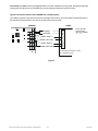
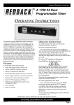
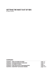
Mounting: Use supplied hardware to attach FA464DR housing to wall or surface.
RECEIVER COVER SCREW ACCESS
(2 PLACES)
WALL MOUNT SCREW ACCESS
(2 PLACES)
Figure 2
© 1999 Inovonics Wireless Corporation 02039F.DOC LIT-FA464-INSTALL
4
hc:21-Nov-03
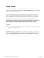
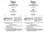
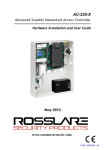
Connecting to a panel: When the FA464DR will be used with a hardwire security panel, the panel will typically
supply power and ground to the FA464DR (if the power supply provides the required current).
Typical connections between the FA464DR and a hardwire panel:
The installer wires the relay common terminal to the panel Zone Return, and wires either the Normally Open or
the Normally Closed terminal of the relay to the panel Zone input terminal.
FA464DR
DC POWER ONLY
12VDC TYPICAL 18VDC MAX
RESE T
LOW BATTE RY
16
INA CTIVE
ADVANCE
13.6VDC
+
GND
TAMPE RED
DELETE
15
PROGRA MME D
14
13
NC COM NO NO COM NC NC COM NO NO COM NC
ACTIVATE D
NC COM NO NO COM NC NC COM NO NO COM NC
TAMPE R
TRANSMITTER
NUMBE R
REVIEW
STATUS
PANEL
TAM PER
TRANSMITTER
PROGRA MMING
GROUND
1
PANEL ZONE 1
2
ZONE 1 RETURN
3
PANEL ZONE 2
4
NOTE: GROUND
AND RETURNS
ARE NOT COMMON
ZONE 2 RETURN
In this example, Panel Zones 1 and 2
are configured to be N/C.
Figure 3
© 1999 Inovonics Wireless Corporation 02039F.DOC LIT-FA464-INSTALL
5
hc:21-Nov-03
Programming transmitters:
Without the FA116 programmer:
1. Refer to Appendix A to determine available default parameters.
2. Select a point number which matches desired transmitter parameters.
3. Press the Advance Button on the FA464DR until the Transmitter Number Display shows the
desired transmitter number. (Hold down the Advance Button for auto repeat.) The Programming
LED will blink if the point has not been programmed. If a transmitter has already been programmed to
that channel, the LED will be on steady.
4. Connect the programming cable to the transmitter and then to the Transmitter Programming Port
on the FA464DR.
5. Press the transmitter reset button. (Refer to.) When the transmitter is successfully programmed, the
receiver will emit a single "deedle" tone and the Programming LED will be on solid. (It may be
necessary to press the transmitter reset button more than once, if the receiver is "busy" with signals
from other transmitters.)
With the FA116 programmer: Up to 64 transmitters can be selected, programmed and deleted. The
programmer allows installers to configure receiver parameters and output options. Point status and signal
strength can be observed. Receiver outputs can be activated for testing and faults can be cleared.
Refer to FA116 programming documentation.
© 1999 Inovonics Wireless Corporation 02039F.DOC LIT-FA464-INSTALL
6
hc:21-Nov-03
Receiver Operation:
Fault output operation: By default, the Global Fault Output will activate upon recognition of a trouble
condition. Tamper and Low Battery signals will cause the Global Fault Output to latch. Inactive conditions
will follow the current state of the transmitter.
A point is declared inactive as follows: The receiver looks for at least one supervisory transmission (or
"check-in") from each supervised transmitter during the period of time programmed as the supervisory
window. The first time the receiver gets a supervisory signal from a transmitter within a new window, it
considers the transmitter active for the remainder of the window. If it fails to get another signal in the
following supervisory window, it declares the point inactive at the end of that window. The actual time
between a transmitter becoming inactive and being reported inactive will range from slightly more than the
supervisory window value to slightly less than twice the window period. For example, the default
supervisory window is 4 hours. If a transmitter becomes inactive, the inactive fault output will be triggered in
4 to 8 hours.
Note: If another output is assigned a global fault function, such as global tamper, that function will no longer
be reported at the Global Fault output.
Displaying fault and active conditions: Faults can be identified by point and type. Press the Review
Button while observing the status LEDs. Trouble conditions will be indicated by LEDs and the point will be
shown on the Transmitter Number Display. The display will show multiple faults, by stepping through
each trouble type in sequence, showing points affected. If a point is activated and/or has a trouble
condition, the Output LEDs will indicate which output is assigned to the activated and/or troubled point.
© 1999 Inovonics Wireless Corporation 02039F.DOC LIT-FA464-INSTALL
7
hc:21-Nov-03
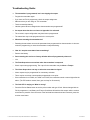
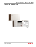
Resetting outputs: All outputs can be reset either by pressing the Reset Button or by pulling the Reset
Input terminal to ground. This can be done by installing a switch between the reset input and the ground
terminal on the receiver. (NOTE: The distance to this switch must not exceed 25 feet). Remote or
automatic resetting can be accomplished by relay control from some hardwire panels. All outputs are
cleared. If a transmitter remains in alarm or if a fault condition is not corrected, the output will reactivate at
the next supervisory signal received from the transmitter.
Reset Circuit Example:
25’ maximum distance
Switch to Receiver
TA MPE R
TRA NSMITTER
PROGRA MMING
RESE T
TAMPE RED
LOW BATTE RY
16
INA CTIVE
ADVANCE
+
GND
DELETE
15
PROGRA MME D
14
13
NC COM NO NO COM NC NC COM NO NO COM NC
ACTIVATE D
REVIEW
STATUS
DC POWER ONLY
12VDC TYPICAL 18VDC MAX
NC COM NO NO COM NC NC COM NO NO COM NC
TAMPE R
TRA NSMITTER
NUMBE R
1
2
3
4
Figure 4
Deleting points: Transmitter programming information remains in non-volatile receiver memory.
Transmitters may be re-programmed using the current parameters.
1. Use the Advance Button to show the desired point on the Transmitter Number
Display.
2. Press the Delete Button on theFA464DRboard. A 3-tone signal will be heard. The
Programmed LED will change from steady "on" to flashing.
3. Points may also be deleted via the FA116 programmer.
Using the FA116 programmer keypad: Program all 64 points with FA116 programmer. Options which
may be programmed include end-of-line resistor, internal contact (widegap magnet), changing external
switch configuration, check-in time interval and desired output channel. In addition, receiver parameters
may be set also, including supervisory window. See
Restoring factory defaults: This sequence restores all factory defaults and clears all programmed points.
Note: This sequence resets the receiver access code to default value (3446).
1. Press and hold the Advance Button.
2. Press and release the Reset Button. A steady tone will begin.
3. Release the Advance Button. The Decode and Valid Decode LEDs will go
out.
4. Press and hold the Delete Button.
5. When a rapid "deedle- deedle- deedle" tone is heard and the Decode LED flashes,
release the Delete Button.
© 1999 Inovonics Wireless Corporation 02039F.DOC LIT-FA464-INSTALL
8
hc:21-Nov-03
Troubleshooting Guide:
i The transmitter is programmed, but is not tripping the output.
Program the transmitter again.
If you have an FA116 programmer, check the output assignment.
Make sure that you are using an "FA" transmitter.
Test the transmitter battery.
Has the system ID been changed since the transmitter was programmed?
i An output other than the one shown in Appendix A is activated.
The receiver's output configuration may have been reprogrammed.
The transmitter may not be programmed to the correct point.
i What does resetting the transmitter do?
Resetting the transmitter recovers the parameters last programmed into the transmitter. It does not
erase the programming or cause the transmitter to stop transmitting.
i How do I stop the transmitter from transmitting?
Remove the battery.
i Does resetting the receiver to factory defaults delete all programmed points too?
Yes.
i The Fault Output does not activate when the transmitter is tampered.
Check output setup programming. The output for the transmitter may be Alarm + Tamper.
i The Alarm Output does not stay on when the transmitter is tripped.
Alarm outputs may be programmed for momentary activation.
There may be more than one transmitter programmed to one point.
If the transmitter is an FA206, an FA204 or an FA207, the transmitter sends a restoral right after the
alarm. (The PIR sends a restoral, then goes to sleep for 90 seconds.)
i The fault LED is staying on. What is wrong?
Press the Review Status button to see the point number and type of fault. Unless changed with an
FA116 programmer, Low Battery and Tamper Conditions will latch the fault output until the receiver
reset button is pressed. Once the cause of the fault had been determined and corrected, press the
receiver reset button.
© 1999 Inovonics Wireless Corporation 02039F.DOC LIT-FA464-INSTALL
9
hc:21-Nov-03
Appendix A
FA464DR Receiver Parameters
Output
1
2
3
4
...
...
16
Default
Active on
Condition
Alarm
Alarm
Alarm
Alarm
Options for each output
ALARM / ALARM+TAMPER / TAMPER /
LO BATT / INACTIVE / TAMP+LO BATT /
TAMP+INACTIVE / LO BATT+INACTIVE /
ANY TX FAULT / DISABLED
Alarm
Transmitter
Condition
Default
Mode
Alarm
Inactive
Tamper
Low Batt
Follower
Follower
Latching
Latching
FOLLOWER / MOMENTARY / LATCHING
"
"
"
Default Momentary Output time: 4 seconds
1 - 16 seconds
Default Receiver Parameters:
System ID:
Point supervision:
Supervision window*:
Access code:
Vision Plus compatible:
(randomly assigned at factory)
0 - 255
Yes
Yes / No
4 hours
1 - 99 minutes, 2 - 99 hours
(Note: use 60 minutes for 1-hour window)
3446
0000 - 9999
No
Yes / No
* Selecting appropriate Supervision Window values: Acceptable values for a supervision window permit
timely notification of inactive points but preclude false inactive reports.
A point is declared inactive as follows: The receiver looks for at least one supervisory transmission (or
"check-in") from each supervised transmitter during the period of time programmed as the supervisory
window. The first time the receiver gets a supervisory signal from a transmitter within a new window, it
considers the transmitter active for the remainder of the window. If it fails to get another signal in the
following supervisory window, it declares the point inactive at the end of the window.
The actual time between a transmitter becoming inactive and being reported inactive will range from slightly
more than the supervisory window value to slightly less than twice the window period. For example, the
default supervisory window is 4 hours. If a transmitter becomes inactive, the inactive fault output will be
triggered in 4 to 8 hours. There are many factors which can prevent individual check in transmissions from
reaching the receiver, so the greatest possible ratio of check-in signals to supervision window is desirable.
For example, typical default settings for Inovonics products include supervision windows of 4 hours and
transmitter check-in times at 60 seconds. In this case, the receiver has 240 "chances" to receive a check-in
transmission per supervision window period. Significantly decreasing this ratio increases the possibility that
the receiver will erroneously declare a point inactive.
When transmitters are set for 60-second check-in, a rule of thumb for setting the supervision window is to
allow at least one hour for each 16 transmitters in the system. Decreasing the supervision window to less
than one hour should only be done in consultation with Inovonics technical service.
© 1999 Inovonics Wireless Corporation 02039F.DOC LIT-FA464-INSTALL
10
hc:21-Nov-03
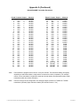
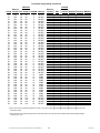
Appendix A (Continued)
DefaultFA464DR Transmitter Parameters
Point# Contact Output
1
N/O
1
2
N/O
2
3
N/C
3
4
N/C
4
5
N/O
1
6
N/O
2
7
N/O
3
8
N/O
4
9
N/C
1
10
N/C
2
11
N/C
3
12
N/C
4
13
N/C
1
14
N/C
2
15
N/C
3
16
N/C
4
17
N/C
5
18
N/C
5
19
N/C
5
20
N/C
5
21
N/C
6
22
N/C
6
23
N/C
6
24
N/C
6
25
N/C
7
26
N/C
7
27
N/C
7
28
N/C
7
29
N/C
8
30
N/C
8
31
N/C
8
32
N/C
8
*Note:
**Note:
Check-In
60 SEC
60 SEC
60 SEC
60 SEC
60 SEC
60 SEC
60 SEC
60 SEC
60 SEC
60 SEC
60 SEC
60 SEC
60 SEC
60 SEC
60 SEC
60 SEC
60 SEC
60 SEC
60 SEC
60 SEC
60 SEC
60 SEC
60 SEC
60 SEC
60 SEC
60 SEC
60 SEC
60 SEC
60 SEC
60 SEC
60 SEC
60 SEC
Point#
33
34
35
36
37
38
39
40
41
42
43
44
45
46
47
48
49*
50
51
52
53
54
55
56
57
58
59
60
61**
62
63
64
Contact Output
N/C
9
N/C
9
N/C
9
N/C
9
N/C
10
N/C
10
N/C
10
N/C
10
N/O
11
N/O
11
N/O
11
N/O
11
N/O
12
N/O
12
N/O
12
N/O
12
N/O
13
N/O
13
N/O
13
N/O
13
N/O
14
N/O
14
N/O
14
N/O
14
N/O
15
N/O
15
N/O
15
N/O
15
N/O+INT
16
N/O+INT
16
N/O+INT
16
N/O+INT
16
Check-In
60 SEC
60 SEC
60 SEC
60 SEC
60 SEC
60 SEC
60 SEC
60 SEC
60 SEC
60 SEC
60 SEC
60 SEC
60 SEC
60 SEC
60 SEC
60 SEC
5 MIN
5 MIN
5 MIN
5 MIN
5 MIN
5 MIN
5 MIN
5 MIN
5 MIN
5 MIN
5 MIN
5 MIN
60 SEC
60 SEC
60 SEC
60 SEC
Points 49-60 are programmed to check in every five minutes. This will extend battery life slightly
depending on which transmitter is used and the environment in which it operates. (For example,
motion or door transmitters in high traffic areas have shorter battery life expectancies than similar
transmitters which are seldom activated.)
Points 61 through 64 are configured to use widegap magnet contacts on FA200W or FA210W
transmitters. (Normally Open external contacts plus Internal Contact = Yes)
© 1999 Inovonics Wireless Corporation 02039F.DOC LIT-FA464-INSTALL
11
hc:21-Nov-03
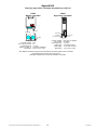
Appendix B
FA210
Universal Transmitter
"
Frequency Agile Series Transmitter Programming
FA210W
Universal Widegap Transmitter
FA202
Smoke Detector
Programming header
Programming
Header
Reset Button
Reset button
+
+
Reed switch
indicator
FA210W Widegap
Reed switches
Tamper switch
Program contacts:
EOL resistor:
Typical battery life:
Battery type:
Switch trigger:
Dimensions:
3.0V
3.0V
N/O or N/C, as needed
as needed
4 years
3.0V lithium DL123A
1.5 seconds, minimum
3.55" x 1.70" x 0.920"
Program contacts:
EOL resistor:
Internal contact:
Typical battery life:
Battery type:
Switch trigger:
Dimensions:
N/O or N/C, as needed
as needed
as needed
4 years
3.0V lithium DL123A
1.5 seconds, minimum
3.55" x 1.70" x 0.920"
Program
Typical battery life:
2 Batteries:
Dimensions:
contacts: N/C
1 year
3V lithium
6.0" Diameter
Note: Remove jumper to program,
replace jumper after programming.
FA203
Pendant Transmitter
FA204
Pendant Transmitter
FA205
Beltclip Transmitter
Reset button
Reset button
Programming header
3.0V
Program contacts:
Typical battery life:
Battery (or equivalent):
Dimensions:
Programming header
+ 3.0V
+
N/O
3-5 years
3.0V lithium Sanyo CR2
3.10" x 1.62" x 0.750"
* To extend battery life, actual check-in interval
of the FA203 is 2 to 3 times the programmed
value.
3.0V
Programming
header
Reset button
Note: Remove battery cover to access
Reset Button and Programming Head
Program contacts:
Typical battery life:
Battery
Dimensions:
N/O
2 years
3.0V Sanyo LiMn CR14250
2.8" x 1.7" x 0.83"
FA206DS
PIR Motion Detector
FA206S
PIR Motion Detector
Program contacts:
Typical battery life:
Battery (or equivalent):
Dimensions:
N/O
3-5 years
3.0V lithium Sanyo CR2
3.10" x 1.62" x 0.750"
* To extend battery life, actual check-in
interval of the FA205 is 2 to 3 times the
programmed value.
FA207
Glassbreak Detector
Programming header
(with tamper shunt)
Programming header
Reset button
+
Programming
header
Reset button
3.0V
Reset button
+
1-zone or 2-zone
detection header
+
3 .0 V
3.0V
Tamper switch
Sensitivity selector
Walk test LED
+
Battery
Mirror Optics
Tamper switch
Program contacts:
Typical battery life:
Battery:
DL123A
Sleep after trip:
Dimensions:
N/C
2 years
3.0V lithium Duracell
90-103 seconds
3.75" x 2.88" x 2.40"
Program contacts:
Typical battery life:
Battery:
Sleep after trip:
Dimensions:
© 1999 Inovonics Wireless Corporation 02039F.DOC LIT-FA464-INSTALL
12
N/C
2 years
3.0V lithium DL123A
180 seconds
3.75" x 5.75" x 2.50"
Program contacts:
Typical battery life:
Battery:
Dimensions:
N/O
2 years
3.0V lithium DL123A
4.25" x 3.12" x 1.63"
Note: Remove jumper to program,
replace jumper after programming.
hc:21-Nov-03
Appendix B
Frequency Agile Series Transmitter Programming, continued
FA250
High Power Transmitter
Delay selector
Tamper switch
3V LITHIUM
3V LITHIUM
Tamper Switch
Reset Button
Programming Header
Reset button
Program contacts:
EOL resistor:
Typical battery life:
Battery type:
Switch trigger:
Dimensions:
Programming header
Program contacts:
EOL, internal contacts:
Typical battery life:
Battery type (Qty. 2):
Dimensions:
N/O
No
1-2 years
3.0V lithium CR2450N
2.63" x 6.19" x 0.750"
3.0V
+
FA209
Billtrap Transmitter
External contact
Terminals
N/O or N/C, as needed
as needed
1-2 years
3.0V lithium DL123A
1.5 seconds, minimum
1.25" x 6.00" x 0.750"
Note: Batteries are always supervised. Lithium batteries are capacity-tested at 18-hour intervals.
Typical battery life is based on 60-second check-in.
Transmitters will deactivate 2 weeks after low battery is detected.
© 1999 Inovonics Wireless Corporation 02039F.DOC LIT-FA464-INSTALL
13
hc:21-Nov-03
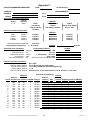
Appendix C
FA464 PROGRAMMING WORKSHEET
COMPANY:
ADDRESS:
PHONE:
Default Receiver Output Parameters
Default
Output
Active on
1 - 16
Alarm
Default Transmitter Output mode
Condition
Default Mode
Alarm
Follower
Inactive
Follower
Tamper
Latching
Low Batt
Latching
DATE:
FILLED OUT BY:
PROGRAMMED BY:
CITY:
ATTN:
Alarm
Low Battery
Tamper+Inactive
Disabled
CHOICES
Alarm+Tamper
Inactive
Low Battery+ Inactive
Tamper
Tamper+Low Battery
Any Tx fault
CHOICES
Momentary
Momentary
Momentary
Momentary
Latching
Latching
Latching
Latching
Follower
Follower
Follower
Follower
4 seconds
Default Momentary Output time:
Programmable Output time:
1 - 16 seconds
Default Receiver Parameters
System ID:
Point supervision:
Supervision window:
Access code:
Vision Plus compatible:
CHOICE:
Programmable Options
0 - 255
(random)
Yes / No
Yes
1 - 99 minutes, 1 - 99 hours
4 hours
0000 - 9999
3446
No
(See FA116 user manual) Yes / No
Default Transmitter Parameters
External Contacts options:
2.2K EOL resistor options:
Internal Contact options:
Output channel options:
Check-In interval options:
seconds
CHOICE
N/O or N/C
Yes or No (in external contact loop)
Yes or No (FA200W and FA210W widegap only)
1 - 16
Unsupervised / 10, 30 or 60 seconds / 5 or 60 minutes / 8 or 18 hours
Transmitter Programming
DEFAULT
External
Internal
Point# Contact EOL Contact Output#
1
N/O
No
No
1
2
N/O
No
No
2
3
N/C
No
No
3
4
N/C
No
No
4
5
N/O
No
No
1
6
N/O
No
No
2
7
N/O
No
No
3
8
N/O
No
No
4
9
N/C
No
No
1
10
N/C
No
No
2
11
N/C
No
No
3
12
N/C
No
No
4
13
N/C
No
No
1
14
N/C
No
No
2
15
N/C
No
No
3
16
N/C
No
No
4
Check-in
60 SEC
60 SEC
60 SEC
60 SEC
60 SEC
60 SEC
60 SEC
60 SEC
60 SEC
60 SEC
60 SEC
60 SEC
60 SEC
60 SEC
60 SEC
60 SEC
© 1999 Inovonics Wireless Corporation 02039F.DOC LIT-FA464-INSTALL
External
Contact
14
EOL
CHOICE
Internal
Contact Output# Check-in (HR/SEC)
hc:21-Nov-03
Transmitter Programming (Continued)
External
Point# Contact
17
N/C
18
N/C
19
N/C
20
N/C
21
N/C
22
N/C
23
N/C
24
N/C
25
N/C
26
N/C
27
N/C
28
N/C
29
N/C
30
N/C
31
N/C
32
N/C
33
N/C
34
N/C
35
N/C
36
N/C
37
N/C
38
N/C
39
N/C
40
N/C
41
N/O
42
N/O
43
N/O
44
N/O
45
N/O
46
N/O
47
N/O
48
N/O
49*
N/O
50
N/O
51
N/O
52
N/O
53
N/O
54
N/O
55
N/O
56
N/O
57
N/O
58
N/O
59
N/O
60
N/O
61**
N/O
62
N/O
63
N/O
64
N/O
DEFAULT
Internal
EOL Contact Output#
No
No
5
No
No
5
No
No
5
No
No
5
No
No
6
No
No
6
No
No
6
No
No
6
No
No
7
No
No
7
No
No
7
No
No
7
No
No
8
No
No
8
No
No
8
No
No
8
No
No
9
No
No
9
No
No
9
No
No
9
No
No
10
No
No
10
No
No
10
No
No
10
No
No
11
No
No
11
No
No
11
No
No
11
No
No
12
No
No
12
No
No
12
No
No
12
No
No
13
No
No
13
No
No
13
No
No
13
No
No
14
No
No
14
No
No
14
No
No
14
No
No
15
No
No
15
No
No
15
No
No
15
No
Yes
16
No
Yes
16
No
Yes
16
No
Yes
16
Check-in
60 SEC
60 SEC
60 SEC
60 SEC
60 SEC
60 SEC
60 SEC
60 SEC
60 SEC
60 SEC
60 SEC
60 SEC
60 SEC
60 SEC
60 SEC
60 SEC
60 SEC
60 SEC
60 SEC
60 SEC
60 SEC
60 SEC
60 SEC
60 SEC
60 SEC
60 SEC
60 SEC
60 SEC
60 SEC
60 SEC
60 SEC
60 SEC
5 MIN
5 MIN
5 MIN
5 MIN
5 MIN
5 MIN
5 MIN
5 MIN
5 MIN
5 MIN
5 MIN
5 MIN
60 SEC
60 SEC
60 SEC
60 SEC
External
Contact
EOL
CHOICE
Internal
Contact Output# Check-in (HR/SEC)
* Note: Points 49-60 are default-programmed to check in every five minutes. This will extend battery life slightly depending on which
transmitter is used.
** Note: Points 61-64 are default-programmed to be Normally Open plus Internal Contact (FA200W and FA210W widegap magnet
contacts) set to "Yes".
© 1999 Inovonics Wireless Corporation 02039F.DOC LIT-FA464-INSTALL
15
hc:21-Nov-03
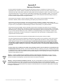
Appendix D
Warranty & Disclaimer
Inovonics Wireless Corporation ("Inovonics") warrants its products ("Product" or "Products") to conform to its own
specifications and to be free of defects in materials and workmanship under normal use for a period of twenty-four (24)
months from the date of manufacture. Within the warranty period Inovonics will repair or replace, at its option, all or any part
of the warrantied product. Inovonics will not be responsible for dismantling and/or reinstallation charges. To exercise the
warranty, the User ("User", "Installer" or "Consumer") must be given a Return Material Authorization ("RMA") Number by
Inovonics. Details of shipment will be arranged at that time.
This warranty does not apply in cases of improper installation, misuse, failure to follow installation and operating
instructions, alteration, abuse, accident or tampering, and repair by anyone other than Inovonics.
This warranty is exclusive and expressly in lieu of all other warranties, obligations or liabilities, whether written, oral,
express, or implied, including any warranty of merchantability or fitness for a particular purpose. Inovonics will not be liable
to anyone for any consequential or incidental damages for breach of this warranty or any other warranties.
This warranty will not be modified, varied or extended. Inovonics does not authorize any person to act on its behalf to
modify, vary or extend this warranty. This warranty will apply to Inovonics Products only. All other products, accessories or
attachments used in conjunction with Inovonics equipment, including batteries, will be covered solely by their own warranty,
if any. Inovonics will not be liable for any direct, incidental or consequential damage or loss whatsoever, caused by the
malfunction of Product due to products, accessories, or attachments of other manufacturers, including batteries, used in
conjunction with Inovonics Products.
This warranty does not warrant the replacement of batteries that are used to power Inovonics Products.
The User recognizes that a properly installed and maintained security system may only reduce the risk of events such as
burglary, robbery, personal injury and fire. It does not insure or guarantee that there will be no death, personal damage
and/or damage to property as a result. Inovonics does not claim that the Product may not be compromised and/or
circumvented, or that the Product will prevent any death, personal and/or bodily injury and/or damage to property
resulting from burglary, robbery, fire or otherwise, or that the Product will in all cases provide adequate warning or
protection.
Inovonics shall have no liability for any death, injury or damage, however incurred, based on a claim that Inovonics
Products failed to function. However, if Inovonics is held liable, directly or indirectly, for any loss or damage arising under
this limited warranty or otherwise, regardless of cause or origin, Inovonics' maximum liability will not in any case exceed the
purchase price of the Product, which will be fixed as liquidated damages and not as a penalty, and will be the complete and
exclusive remedy against Inovonics.
!
!
Warning: The User should follow all installation, operation and maintenance instructions. The User is strongly
advised to conduct Product and systems tests at least once each week. Changes in environmental conditions, electric or
electronic disruptions and tampering, may cause the Product to not perform as expected.
Warning: Inovonics warrants its Product to the User. The User is responsible for exercising all due prudence and taking
necessary precautions for the safety and protection of lives and property wherever Inovonics Products are installed.
Inovonics strongly advises the User to program Products to be supervised whenever used in applications affecting life safety.
Users are warned that unsupervised devices are subject to undetected failure due to malfunction, battery failure, tampering,
or changes in environment.
© 1999 Inovonics Wireless Corporation 02039F.DOC LIT-FA464-INSTALL
16
hc:21-Nov-03
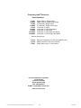
Frequency Agile® Receivers
from Inovonics:
FA401
FA401R
FA404
FA404R
FA416
FA416D
FA416R
FA416DR
FA464DR
Single Channel / Single Output
Single Channel / Single Relay Output
4-Transmitter / Single Output
4-Transmitter / Single Relay Output
16-channel / 4-output
16-channel / 4-output with display
16-channel / 4-relay output
16-channel / 4-relay output with display
64-channel / 16-relay output with display
Receiver Accessories:
FA116
FA516
FA541
Executive Programmer for FA416 /FA464DR/ C404
Display module for FA416 and FA416R
Single-channel form ‘C’ relay module
Inovonics Wireless Corporation
315 CTC Blvd
Louisville CO 80027
Phone (800)782-2709
FAX: (303)939-8977
E-MAIL: [email protected]
www.inovonics.com
© 1999 Inovonics Wireless Corporation 02039F.DOC LIT-FA464-INSTALL
17
hc:21-Nov-03