1
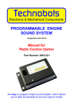
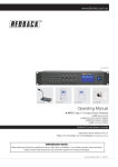
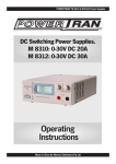
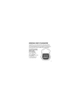
www.altronics.com.au
®
A 1700 24 Hour
Programmable Timer
OPERATING INSTRUCTIONS
This simple to operate digital timer allows numerous
variations of ON/OFF cycles every 24 hours. It can be
configured to 14 on cycles every day. Additionally , it
may be programmed to operate on any combination of
days ( ie. weekdays or weekends). The on duration is
variable and can be set from 1 second to 23 hours 59 minutes and 59 seconds. It is ideal for programming period
breaks in schools or change of shift bells in factories and
work places. The in-built digital clock can be set to one of
three modes of operation, manual , automatic and off. In
the manual mode you may override any programmed
setting , the automatic mode switches on at the pre-programmed times and the off mode disables the pre programmed on times.
OPERATING INSTRUCTIONS
To install and operate the unit you will need to
programme the timer as follows.
1) Set the current time and day .
To set the current day or time press the P key to
clear the entire memory. Hold down the CLOCK key and
press either the DAY, HOUR, MIN or SEC key
continuously until the desired day or time is shown.
Then lift your finger off the CLOCK key to start the timer
operating.
2) Set the ”ON” duration for all programs
Press TIMER key, the display will show :
ON
FEATURES
• 19” 2U Rack mount or desk mount
• Timer may trigger Chime or 24VDC out
• Choice of 240VAC or 24VDC operation
• Choice of 5 tones for the bell chime
• In-built manually operated Alert/ Evac switches
• Remote trigger contacts for Alert,Evac and Chime
• Programs are retained during power failure
• Up to 14 “ON” programs per 24 hours
• Unit may be programmed to operate on any
combination of days
• 2 Year warranty
• Made in Australia
TIME
ADJ
Set the duration of all the programs (T1) by pressing
HOUR, MIN and SEC keys until the desired “ON”
duration is displayed. It is recommended that you use
durations of no more than 1 second for a single chime
tone. For longer chime durations you will need to set dip
switch 3 to ON as well as programming the ON duration
for a longer period.
To review the programmed duration , press the timer
button when in timer function.
3) Set the programmed “ON” times.
After setting the ON duration, press the TIMER
button again to bring up the first “ON” program.
Use HOUR , MIN and SEC buttons to set the first
program start time. Use the DAY button to set the
desired day or sequence of days this program will
operate on.
You may then press TIMER again to set the “ON” time
for programs 2 - 14.
Distributed by Altronic Distributors Pty. Ltd. Perth. Western Australia.
Proudly Assembled in Australia
Doc. PS1215
Page 1
REDBACK A 1700 Programmable Timer
OFF.
To exit programming press the CLOCK button , this will
return you to the timer function.
REAR WIRING CONNECTIONS
To review a programmed “ON” time press the TIMER
button until the program you wish to alter is displayed.
The connections on the rear of the unit require some
explanation in order to set up for continuous trouble free
use.
4) Switch the unit to “Auto” mode.
For the programmed “ON” times to operate the unit
must be switched to Auto mode. Use the button marked
MANUAL until the dash indicator is above the word
AUTO. In this mode the programs will function at the
prescribed times and days.
The 10 way pluggable terminal is labelled Evac, Alert,
Chime, 24V Out and Timer 24V Out.
The terminals activate the assigned tone, e.g. if you want
the ALERT to sound from a remote location the contacts
may be connected to a normally open switch which when
pressed will trigger the ALERT tone and will then sound
as if the ALERT button on the front panel was pushed,
and the same applies to the EVAC and CHIME terminals.
5) Use of Manual or Off
Manual operation allows the user to override a program.
To use the timer in manual mode press the MANUAL
key until the dash indicator is over the word On.
The 24VDC switched out terminal has no output until a
button or the timer activates a tone. When a tone is activated 24VDC is present across the positive and negative
terminals .
This will turn the timer on. The timer will stay triggered
until you manually set the timer to the “OFF” position.
To set the timer to the off position press the MANUAL
key until the dash indicator is over the word Off.
TABLE 1 : DIP SWITCH SETTINGS
Switch Number
Chime Tone: Single Bing
1
2
3
There is a switch next to the Timer 24V Out terminal on
the rear of the unit. This allows you to select whether the
timer “ON” cycle triggers the Timer 24V out contacts or
the chime. If this switch is in the “Up” position , the timer
will cause 24VDC to appear across the “Timer 24V out “
contacts. In the “Down” position , the timer will trigger
the chime.
4
OFF OFF OFF
–
Bing Bong
OFF OFF
ON
–
Single Bong
ON
OFF OFF
–
Siren
ON
ON
OFF
–
Deedle Tone
OFF
ON
OFF
–
*Repeating Bong
ON
OFF
ON
–
*Repeating Siren
ON
ON
ON
–
The RCA Sockets are line level (1V) outputs, which are
run to an amplifier or mixer input.
*Repeating Deedle OFF
ON
ON
–
Power Supply
Note : this switch will be factory set to “Down”.
* These tones will sound continuously for the duration of
the timer or as long as the chime button is pressed.
The power for the unit may come from either 24VDC or
240 AC , for 240V operation simply plug the 240V power
cord into the socket labelled 240VAC.
Chime Tone Switch Settings
For 24VDC operation , use the terminal marked 24VDC.
To set the tone for “ON” cycle , use the dip switch setting
table to obtain the type of tone you wish to output.
Caution: The 24VDC is polarised and may cause damage to the unit if not connected correctly. The polarity is
marked on the unit, just under the terminal.
The factory setting for the chime tone will be single Bing.
Dip switch 4 makes the alert/evac tone cycle
continuously after it is triggered or stay on only while the
Alert/evac button is held down.
Power only needs to be in one form either AC or DC to
work. Both 24VDC and 240VAC can be connected at the
same time (for battery backup).
To enable the alert /evac to operate continuously switch
dip switch 4 to ON. Note that this will be factory set to
Volume Controls
Key
8
1
2 3
4
5 6
7
9 10 11 12 13 14
Rear view
Page 2
1. 240V AC power in
2. 24VDC power input
3. DC Fuse (3A)
4. Chime Level
5. Voice-over Level
6. Alert/Evac Level
7. Dip Switches
8. Line Output (RCA)
9. Evac remote contacts
10. Alert remote contacts
11. Chime remote contacts
12. 24VDC output
13. Timer switched 24VDC
14. Chime/24VDC switch
Doc. PS1215
REDBACK A 1700 Programmable Timer
The volume controls can be found on the rear of the unit,
these should be adjusted with a small phillips head screwdriver or adjustment tool.
Chime Volume controls the output level of the Chime.
Voice Over controls the level of the optional Voice Over
module (A 2072) if installed.
Mic
Pin 1
Alert/Evac Volume controls the level of the Alert and Evac
tones.
Relays
Adjust the output volumes to the desired levels.
Use ribbon cable &
connectors provided
to join terminals (Pin
1 is the black pin)
THE OPTIONAL VOICE OVER MODULE
The A 1700 timer panel has the option to fit the A 2072
voice over module. This will add a voice message to the
evacuation cycles when the evacuation cycle is triggered.
Use with the A 1700 Timer and tone generator
Connection to the A 1700 is via the 5 way keyed header
cable (JP1). The Voice-over Module will play a recorded
message twice in succession after every four evacuation
cycles. The volume control on the A 1700 Timer , labelled
“Voice over level” is used to vary the volume ratio between
the evacuation tones and the voice playback.
IC
Pin 1
Diagram to connect up the A 2072 Voice over module to the timer.
Refer to the text and the instructions for the A 2072 to assist in the
connection
TROUBLESHOOTING
UNIT DOES NOT SWITCH ON AT THE
REQUIRED HOUR
Check programs for the correct switch on times.
5 Pin Header (JP1) Pinouts
Pin
Function
Description
1
Vcc
Regulated +5V input*
2
GND
Ground 0V
3
AUDIO
Audio output, line level 10kΩ
4
PLAY
A momentary high to activate
the message playback
5
PLAYING This line goes low to indicate a
message is currently being played
BATTERY REPLACEMENT
Periodically the CR2302 lithium battery located within the
time clock (Altronics part No. S 4999) should be replaced,
this should not be necessary to be done more often than
once in 4- 5 years , or should the timer begin to loose programs or time. To replace the lithium battery in the unit,
disconnect power to the unit. Open the lid and peel off the
label on the rear of the timer. You will then see a screw type
battery cover. Un-screw this cover and remove the old battery. Checking that the orientation is correct place the new
battery in the timer and screw down the cover. The panel
should now have a reading on the display.
You will need to re-programme the settings on the timer
(refer to that part of the operating section for instructions on
re-programming the settings on the timer ).
Check timer for the correct time.
UNIT DOES NOT SWITCH OFF AFTER
THE ELAPSED TIME
Check timer for the correct “ON” time.
NO POWER TO UNIT
Check DC fuse.
Check power switch is on and confirm unit is plugged in
to either 24VDC or 240VAC.
TIMER FAILS TO TRIGGER TONE / 24V
OUT
Check that the timer 24VDC out switch is set correctly.
Check line out connections to amplifier/ preamp.
Check connections to timer 24VDC out terminals.
TIMER FAILS TO DISPLAY OR KEEP
CORRECT TIME
Replace battery in timer.
ALERT/ EVAC CONTINUE TO OPERATE
AFTER THE SWITCH IS RELEASED
Check dip switch settings.
INCORRECT TYPE OF TONE SOUNDING
WHEN CHIME IS PUSHED
Check Dip switch settings
EVAC, CHIME OR VOICE OVER LEVEL
TOO LOW
Adjust volume controls.
Doc. PS1215
Page 3
REDBACK A 1700 Programmable Timer
A Circuit Diagram of the A 1700 Timer/ Tone generator.
Not field serviceable: For repair contact
Altronics for your nearest Service Centre :
Altronic Distributors Pty. Ltd. Perth W.A. 6000
Phone: (08) 9428 2199 Fax: (08) 9428 2198
SPECIFICATIONS
OUTPUT LEVEL: .....................................1V (Line level)
DISTORTION: .......................................................0.01%
FREQ. RESP.: .........................................140Hz - 20kHz
SIGNAL TO NOISE RATIO:
Alert/Evac/Chime: ............................-70dB typically
OUTPUT CONNECTORS:
Audio Output: ...........................RCA Stereo Socket
Switched 24V DC Out:............Pluggable Terminals
Timer activated 24V DC Out: .Pluggable Terminals
INPUT CONNECTORS:
24V DC Power: ........................Pluggable Terminals
240V AC Power:.........................IEC Chassis Socket
Remote Alert, Evac, Chime:......Pluggable Terminals
CONTROLS:
Day, Hour , Minute, Second
Clock, Manual/ Auto/ Off set............Timer controls
Tone Selection /
Alert Evac operation...........................Dip Switches
Alert, Evac, Chime, Voice over: ........Rear Volume
Power: ................................................On/Off Switch
Alert Switch: ......................Illuminated Push Switch
Evac Switch: ......................Illuminated Push Switch
Bell / Chime Switch:..........Illuminated Push Switch
Cancel Switch:...............................Push Switch
INDICATORS: ..........................................Power on LED
POWER SUPPLY: ..........................240V AC or 24V DC
DIMENSIONS:..............................≈ 482W x 152D x 44H
WEIGHT: ........................................................... ≈ 2.3 kg
COLOUR: ...............................................................Black
OPTIONS: ............................A 2072 Voice Over Module
* Specifications subject to change without notice.
Distributed by Altronic Distributors Pty. Ltd. Perth. Western Australia.
Phone: 1300 780 999 Fax: 1300 790 999
Internet: www.altronics.com.au
Page 4
Doc. PS1215