1
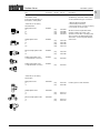
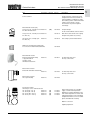
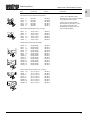
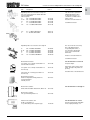
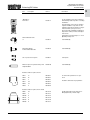
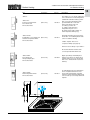
Valves, controls + systems
Innovation + Quality
Products Catalog
Hydronic Catalog
Page
Thermostats
Radiator Valves
Zone Valves
Balancing Valves
PIC Valves
Balancing and PIC Valve Accessories
Control Valves
Hydronic Components
Thermostats—direct connection models
M 30 x 1.5 for Oventrop zone/radiator valves
4
Remote Thermostats
M 30 x 1.5 for Oventrop zone/radiator valves
for squeeze zone/radiator valves
6
Thermostats—direct connection models
for RA squeeze zone/radiator valves
and radiators with squeeze integrated distributor
7
Accessories for thermostats
8
Zone/radiator valves
Hot water systems
9
Zone/radiator valves
Hot water valves with PEX connection
Thermostatic radiator valve packages
10
Zone/radiator valves
Designer “Series E”
Matching thermostat “Uni SH”
11
Zone/radiator valves
Steam systems
One-pipe radiator injection valve
12
Valve inserts
“Demo Bloc” tool
13
Radiator Lockshield Valves “Combi 2”
Radiator Lockshield Valves “Combi 4”
Fittings “Multiflex”
14
Two-way zone valve
Two-way control and balance valve “Cocon Q”
15
Electrothermal actuator
Electromotive actuator
Non-electric actuator with snap-on sensor
16
“Hydrocontrol” manual balancing valves
“Cocon Q” pressure independent control valves
17
“Hydrocontrol-R” manual balancing coil hookup kits
18
“Hydrocontrol-R” Y-strainer ball valve for coil hookup kits
19
“Cocon Q” pressure independent control valve coil hookup kits
20
“Cocon Q” pressure independent control valves
21
Measuring tool “DMC-2”
“Hydrocontrol” accessories
Insulation shells
22
Three-way valves
23
Pressure actuated bypass valve
Airvent
24
1
3
5
1
Hydronic Catalog
Page
Stations for Heating Circuit
Solar Thermal Products
DynaTemp Wireless Thermostats
Heating Oil Filters
Radiant Heating
2
System “Regumat 130” DN 25
“Regumat” accessories
25
6
Solar thermal collectors
26
7
Solar pumping stations
27
Solar storage tanks
28
Wireless thermostat
Wireless actuator
29
Fuel oil filters
Replacement elements
Floating suction kit
30
Manifold for radiant floor heating
and flow control for individual emitters
31
“Unibox” non-electric flow and temperature balance
for underfloor heating
32
PEX pipe with O2 barrier
33
Oventrop Corporation Limited Warranty
34
Terms and Conditions
35
Alphabetical Index
37
Numerical Index
38
8
9
13
General Notes
Notes
Oventrop’s Standard Terms and
Conditions of Sale and Warranty apply.
If not stated otherwise, all hydronic parts in
this list are suitable for hot water with an
operating temperature of up to 240 °F and
an operating pressure of up to 50 psi.
For information on additional items,
please visit our website
www.oventrop-us.com
Upon request, we will gladly investigate
availability and pricing of items not
mentioned in this book.
3
Direct Connection Models
M 30 x 1.5 for Oventrop Zone/radiator Valves
for Squeeze Zone/radiator Valves
and Radiators With Integrated Distributor
Thermostats
Item
Thermostat “Uni XH” connection thread M 30x1.5
with liquid sensor
white model
Box qty. Item no.
(10)
101 13 65
Information
These actuators provide a simple means of
controlling space temperature by adjusting
the flow rate through the heater.
Modulating (not on-off) control that enables
automatic matching of heat loss.
Temperature setting may be limited and set by
user. Memory disc to mark favorite setpoint.
Maximum heating water temperature 248 °F.
“0” setting = positive “off”
“f” setting = freeze protection
white model
with remote sensor
capillary 6½ feet
(10)
101 15 65
capillary 16 feet
(10)
101 15 66
Thermostat ”Uni XD”
squeeze connection
with liquid sensor
white model
These thermostats can be fitted without an
adapter to Danfoss valves, series RA (squeeze
connection) and Buderus radiators with
integrated valve assembly.
(10)
101 13 75
(10)
101 15 75
(10)
101 30 66
Thermostat ”Vindo”
squeeze connection
with liquid sensor
compact
white model
4
Temperature range 42 - 84 °F
Markings on the dial 0,f, 1-5
Temperature setting may be limited by user
through use of hidden limiting guides.
Maximum heating water temperature 248 °F.
“0” setting = positive “off”
“f” setting = freeze protection
Thermostat “Vindo”
connection thread M 30x1.5
with liquid sensor
compact
white model
Squeeze connection with collar nut:
easy installation
close connection
Temperature setting may be limited and set by
user. Memory disc to mark favorite setpoint.
Maximum heating water temperature 248 °F.
“0” setting = positive “off”
“f” setting = freeze protection
white model
with remote sensor
capillary 6½ feet
Temperature range 42 - 84 °F
Markings on the dial 0,f, 1-5
Temperature range 42 - 84 °F
Markings on the dial 0,f, 1-5
These thermostats can be fitted without an
adapter to Danfoss valves, series RA (squeeze
connection) and Buderus radiators with
integrated valve assembly.
(10)
101 30 76
Same setting features as “Vindo” above.
1
Direct Connection Models
M 30 x 1.5 for Oventrop Zone/radiator Valves
and Radiators With Integrated Distributor
Thermostats
Item
1
Box qty. Item no.
Information
white model
(10)
101 14 65
chrome model
(10)
101 14 69
Temperature setting may be limited or locked
by use of internal and tamper-resistent
limiting guides. Tool is required for limiting and
locking. See page 8 for ring loosening tool.
Memory disc to mark favorite setpoint.
Maximum heating water temperature 248 °F.
“0” setting = positive “off”
“f” setting = freeze protection
Thermostat “Uni LH”
connection thread M 30x1.5
with liquid sensor
white model
with remote sensor
capillary 6½ feet
(10)
101 16 65
(10)
101 14 75
(10)
101 16 85
Temperature range 42 - 84 °F
Markings on the dial 0,f, 1-5
Thermostat “Uni LD”
squeeze connection
with liquid sensor
oventrop
white model
white model
with remote sensor
capillary 6½ feet
Maximum heating water temperature 248 °F.
“0” setting = positive “off”
“f” setting = freeze protection
Thermostat “Uni DH”
with wax sensor compact model
connection thread M 30x1.5
1 2
3
4 5
oventrop
white model
(10)
101 10 65
white model with remote sensor
1 2
3
oventrop
capillary 6½ feet
(10)
101 11 65
Without “0” positive off setting
Temperature range 42 - 84 °F
Markings on the dial f, 1-5
With easy-to-read setting device.
Maximum heating water temperature 248 °F.
“0” setting = positive “off”
“f” setting = freeze protection
Thermostat “Uni SH”
with liquid sensor
connection thread M 30 x 1.5
marking “Uni SH” hidden inside
white/chrome plated model
(10)
101 20 65
in stainless steel finish
(10)
101 20 85
Thermostat “Uni LHB”
with liquid sensor
connection thread M 30 x 1.5
white model
Temperature range 42 - 84 °F
Markings on the dial 0,f, 1-5
(10)
101 14 10
Temperature range 42 - 84 °F
Markings on the dial 0,f, 1-5
With mounted design cover.
Lockshield configuration with integrated
anti-theft device. Increased flectional strength
up to 220 lbs. Setting key is required for
setting the temperature value. See page 8 for
setting tool.
Without “0” positive off setting
Temperature range 42 - 84 °F
5
4 5
Remote Thermostats
M 30 x 1.5 for Oventrop Zone/radiator Valves
for Squeeze Zone/radiator Valves
Thermostats
Item
Box qty. Item no.
Information
for Oventrop zone/radiator valves
M 30 x 1.5 connection
2
3
4
1
5
0
2
3
Thermostat with remote control “Uni FH”
with liquid sensor
connection thread M 30 x 1.5
white model
capillary 6½ feet
(40)
101 22 95
capillary 16 feet
(40)
101 22 96
capillary 33 feet
(40)
101 22 97
capillary 6½ feet
(40)
101 23 95
capillary 16 feet
(40)
101 23 96
Wall-mounted thermostats with remote
control and remote transmission (for radiators,
baseboard, floor heating, fan coils).
Temperature setting may be limited or locked
through use of internal limiting guides.
Maximum heating water temperature 248 °F.
“0” setting = positive “off”
“f” setting = freeze protection
Temperature range 42 - 84 °F
Markings on the dial 0,f, 1-5
white model
with additional remote sensor
4
1
5
0
for Danfoss radiator valves
RA squeeze connection
2
3
4
1
5
Thermostat with remote control “Uni FD”
squeeze connection
with liquid sensor
These thermostats can be fitted without
an adapter to Danfoss valves, series RA
(squeeze connection).
Wall-mounted thermostats with remote control and remote transmission (for radiators,
baseboard, floor heating, fan coils).
0
white model
capillary 6½ feet
(40)
101 22 75
Temperature setting may be limited or locked
through use of internal limiting guides.
Maximum heating water temperature 248 °F.
“0” setting = positive “off”
“f” setting = freeze protection
Temperature range 42 - 84 °F
Markings on the dial 0,f, 1-5
6
1
Direct Connection Models
for RA Squeeze Zone/radiator Valves
and Radiators With Squeeze Integrated Distributor
Thermostats
Item
Box qty. Item no.
Thermostat ”Uni XD”
squeeze connection
with liquid sensor
white model
1
Information
These thermostats can be fitted without an
adapter to Danfoss valves, series RA (squeeze
connection) and Buderus radiators with
integrated valve assembly.
(50)
101 13 75
Squeeze connection with collar nut:
easy installation
close connection
Temperature setting may be limited and set by
user. Memory disc to mark favorite setpoint.
Maximum heating water temperature 248 °F.
“0” setting = positive “off”
“f” setting = freeze protection
white model
with remote sensor
capillary 6½ feet
(10)
101 15 75
Thermostat “Uni LD”
squeeze connection
with liquid sensor
white model
(10)
101 14 75
(10)
101 16 85
Temperature range 42 - 84 °F
Markings on the dial 0,f, 1-5
oventrop
white model
with remote sensor
capillary 6½ feet
Thermostat ”Vindo”
squeeze connection
with liquid sensor
Compact
white model
These thermostats can be fitted without an
adapter to Danfoss valves, series RA (squeeze
connection) and Buderus radiators with
integrated valve assembly.
(10)
101 30 76
Temperature setting may be limited by user
through use of hidden limiting guides.
Maximum heating water temperature 248 °F.
“0” setting = positive “off”
“f” setting = freeze protection
Temperature range 42 - 84 °F
Markings on the dial 0,f, 1-5
2
3
4
1
5
Thermostat with remote control ”Uni FD”
squeeze connection
with liquid sensor
0
white model
capillary 6½ feet
(40)
101 22 75
Wall-mounted thermostats with remote control and remote transmission (for radiators,
baseboard, floor heating, fan coils).
Temperature setting may be limited or locked
through use of internal limiting guides.
Maximum heating water temperature 248 °F.
“0” setting = positive “off”
“f” setting = freeze protection
Temperature range 42 - 84 °F
Markings on the dial 0,f, 1-5
7
Thermostats
Item
Right angle pattern adapter
M 30 x 1.5/M 30 x 1.5
white model
Accessories
Box qty. Item no.
(10)
101 14 50
101 14 52
Thread adapter, nickel plated
from M 30 x 1.0 to M 30 x 1.5
101 14 45
oventrop
8
For the conversion of actuator connection
thread
Transposes setting numbers from horizontal to
vertical reading.
“Uni-Clip”
vertical reading adapter ring
for “Uni XH” and “Uni XD” thermostats
Thermostat mounted right side
(50)
101 13 96
Thermostat mounted left side
(50)
101 13 97
Vandal guard
for thermostat ”Uni XH”
white model
(25)
101 17 66
Vandal guard
for thermostat ”Uni DH”
white model
For the connection of the thermostats at a
right angle.
For Oventrop radiator valves with connection
M 30 x 1.5.
For Danfoss radiator valves series RA, or for
Buderus radiators.
Right angle pattern adapter
squeeze connection/squeeze connection
white model
(10)
(10)
Information
(10)
101 19 11
2 piece trim ring
to hide nickel plated lock nut of “Uni XH” (50)
101 13 93
Manual temperature adjuster
for all valves with M 30 x 1.5 thread
101 25 65
(10)
with squeeze connection for Danfoss valves
101 25 75
“Uni LH” tool
To loosen the graduation cap and clip
Bag of 5 pieces
198 91 00
“Uni LHB” setting key
for lockshield thermostat “Uni LHB”
101 14 97
Prevents unauthorized removal of thermostat.
Includes Allen key.
Minimum order quantity = 5
Minimum order quantity = 5
To set the nominal temperature value for the
thermostat.
1
Radiator Valves
Item
Hot water systems
Connection Box qty. Item no.
1
Information
The Oventrop “Series AZ” radiator valves
can be used with four types of actuators:
Zone/radiator valves
Connection thread M 30 x 1.5
bronze/brass, nickel plated
1. Manual adjuster (included)
2. Thermostat (non-electric)
3. Thermostat-remote control (non-electric)
4. 24 V electric for on/off control
“Series AZ” (for hot water)
Threaded valves
Angle pattern valve
NPT/NPT
½”
¾”
1”
1¼”
(25)
(25)
(10)
(10)
188 90 04
188 90 06
188 90 08
188 90 10
Straight pattern valve
NPT/NPT
½”
¾”
1”
1¼”
(25)
(25)
(10)
(10)
188 91 04
188 91 06
188 91 08
188 91 10
Reversed angle pattern valve
NPT/NPT
½”
¾”
(25)
(25)
188 92 04
188 92 06
Double angle pattern valve
NPT/NPT
½” left hand side connection
(25)
169 40 62
Double angle pattern valve
NPT/NPT
½” right hand side connection
(25)
169 40 63
Angle pattern valve
SWT/SWT
1
/2”
3
/4”
(25)
(25)
169 44 04
169 44 06
Straight pattern valve
SWT/SWT
1
/2”
3
/4”
(25)
(25)
169 44 14
169 44 16
Reversed angle pattern valve
SWT/SWT
1
/2”
3
/4”
(25)
(25)
169 44 24
169 44 26
All valve inserts are replaceable under
working conditions by means of the
special tool ”Demo-Bloc.” Heating system
does not need to be drained when using
“Demo-Bloc” for removing and replacing
valve inserts.
+ -
- +
“Series AZ” (for hot water)
Sweat valves
Includes (2) unions and sweat tails.
9
Hot Water Valves With PEX Connection
Thermostatic Radiator Valve Packages
Radiator Valves
Item
Connection
Box qty. Item no.
“Series AZ” (for hot water)
Connection thread M 30 x 1.5
bronze/brass, nickel plated
PEX valves
Information
PEX connection on inlet to radiator valve.
The Oventrop “Series AZ” radiator valves
can be used with four types of actuators:
Angle pattern valve
PEX/NPT
½”
(25)
169 66 04
Straight pattern valve
PEX/NPT
½”
(25)
169 66 14
Reversed angle pattern valve
PEX/NPT
½”
(25)
169 66 24
1. Manual adjuster (included)
2. Thermostat (non-electric)
3. Thermostat-remote control (non-electric)
4. 24 V electric for on/off control
All valve inserts are replaceable under
working conditions by means of the special tool ”Demo-Bloc.”
1 - Thermostatic radiator valve package with NPT threaded
connection for 1/2” pipe, consisting of thermostat 101 30 66, angle
pattern valve 188 90 04, and angle pattern lockshield balancing
valve 109 10 82
Item Number
188 90 04K
2 - Thermostatic radiator valve package with NPT threaded
connection for 1/2” pipe, consisting of thermostat 101 30 66, angle
pattern valve 188 92 04, and angle pattern lockshield balancing
valve 109 10 82
Item Number
188 92 04K
3 - Thermostatic radiator valve package with NPT threaded
connection for 1/2” pipe, consisting of thermostat 101 30 66,
straight pattern valve 188 91 04, and straight pattern lockshield
balancing valve 109 11 82
Item Number
188 91 04K
4 - Thermostatic radiator valve package with solder connection for
1/2” copper pipe, consisting of thermostat 101 30 66, angle pattern
valve 169 44 04, and angle pattern lockshield balancing
valve 109 10 92
Item Number
169 44 04K
5 - Thermostatic radiator valve package with solder connection
for 1/2” copper pipe, consisting of thermostat 101 30 66, reversed
angle pattern valve 169 44 24, and angle pattern lockshield
balancing valve 109 10 92
Item Number
169 44 24K
6 - Thermostatic radiator valve package with solder connection
for 1/2” copper pipe, consisting of thermostat 101 30 66, straight
pattern valve 169 44 14, and straight pattern lockshield balancing
valve 109 11 92
Item Number
169 44 14K
7 - Thermostatic radiator valve package with compression
connection for 1/2” PEX pipe, consisting of thermostat
101 30 66, angle pattern valve 169 66 04, and angle pattern
lockshield balancing valve 109 10 52
Item Number
169 66 04K
8 - Thermostatic radiator valve package with compression
connection for 1/2” PEX pipe, consisting of thermostat
101 30 66, reversed angle pattern valve 169 66 24, and angle
pattern lockshield balancing valve 109 10 52
Item Number
169 66 24K
9 - Thermostatic radiator valve package with compression
connection for 1/2” PEX pipe, consisting of thermostat 101 30 66,
straight pattern valve 169 66 14, and straight pattern lockshield
balancing valve 109 11 52
Item Number
169 66 14K
10
1
Designer “Series E”
Matching Thermostat “Uni SH”
Radiator Valves
Item
Connection
Box qty. Item no.
Designer series for use with towel racks or
panel radiators. Includes valve insert AD6
(6 flow presettings).
Radiator valves ”Series E”
Connection thread M 30 x 1.5
Angle pattern valve
BSP
½” chrome plated
½” white powder coated
116 30 52
116 30 62
Straight pattern valve
BSP
½” chrome plated
½” white powder coated
116 31 52
116 31 62
Double angle pattern valve
BSP
left hand side connection
½” chrome plated
½” white powder coated
+
-
right hand side connection
+
-
Gold plated or anthracite models upon
request.
Awards:
Design Award of North Rhine
Westphalia, Award of Honour for
Industrial Products
Industrial Design Forum Hannover
Award iF
116 34 52
116 34 62
BSP
Design Innovationof DesignCentre Essen Award for High Quality of Design
Pragotherm, Prague
½” chrome plated
½” white powder coated
116 34 53
116 34 63
German Institute for Copper Berlin
Award ”Product and Brass”
Normally used on return side of radiator
or towel rack. Allows isolation, balancing
with fill and drain capabiltity.
Service valve ”Combi E”
Angle pattern
BSP
½” chrome plated
½” white powder coated
Straight pattern
1
Information
116 60 52
116 60 62
BSP
½” chrome plated
½” white powder coated
116 70 52
116 70 62
With easy-to-read setting device.
Maximum heating water temperature 248 °F.
“0” setting = positive “off”
“f” setting = freeze protection
Thermostat “Uni SH”
with liquid sensor
connection thread M 30 x 1.5
marking “Uni SH” hidden inside
white/chrome plated model
(10)
101 20 65
stainless steel finish
(10)
101 20 85
Temperature range 42 - 84 °F
Markings on the dial 0,f, 1-5
With mounted design cover.
11
Steam Systems
One-pipe Radiator Injection Valve
Radiator Valves
Item
Connection Box qty. Item no.
Information
“Series S” (for low pressure steam, max.15 psi)
Steam radiator valve
Threaded valves
One-pipe steam radiator valve
NPT
⅛”
(25)
188 85 51
½”
(25)
189 90 04
¾”
(25)
189 90 06
1”
(25)
189 90 08
1¼”
(25)
189 90 10
½”
(25)
189 91 04
¾”
(25)
189 91 06
1”
(25)
189 91 08
1¼”
(25)
189 91 10
½”
(25)
189 92 04
¾”
(25)
189 92 06
Angle pattern valve
Straight pattern valve
Reversed angle pattern valve
NPT/NPT
NPT/NPT
NPT/NPT
Connections
½” to radiator
¾” (Euroconus) to system
with vertical insertion tube
12
1. Manual adjuster (included)
2. Thermostat (non-electric)
3. Thermostat-remote control
(non-electric)
4. 24 V electric for on/off control
All valve inserts are replaceable under
working conditions by means of the
special tool ”Demo-Bloc”. Heating system
does not need to be drained when using
“Demo-Bloc” for removing and replacing
valve inserts.
The minimum bypass of the one-pipe
radiator injection valves is 35%. Bypass
cannot be closed.
The insertion tube is 6” long, has a diameter of 7⁄16” and the distance between pipe
centers is 2 inches.
One-pipe radiator injection valves
with constant bypass and shut off
with horizontal insertion tube
The Oventrop “Series S” radiator valves
can be used with four types of actuators:
118 35 61
118 35 71
The one-pipe radiator injection valve with
vertical insertion tube is especially suitable
for towel radiators. (The technical instructions of the radiator manufacturers need
to be observed.)
1
Valve Inserts
“Demo Bloc” Tool
Radiator Valves
Item
4ºF Cv
Item no.
Standard with Oventrop zone/radiator valves
Valve inserts
for all valves M 30 x 1.5, excluding 101 70 60
Valve insert “Series AZ”
1.28
1
Information
118 70 60
M 30 x 1.5 highest Cv.
Valve insert “Series AZ”
M 30 x 1.0
101 70 60
Valve insert “Series AV 6”
with presetting
0.75
118 70 57
Adjustable Cv valve insert, allows technician
to balance flow rate. Six different settings.
Use key for setting adjustment no. 118 39 61
Valve insert “Series ADV 6”
“Landlord model”
0.75
118 60 01
Same as “Series AV 6”, but with additional
feature that, if thermostat is removed, flow will
be restricted to 5% of normal flow.
Use key for setting adjustment no. 118 39 61
Valve insert “Series S”
Valve insert with stainless steel seat
0.70
118 62 00
Steam specialty insert for steam systems.
Special valve insert
0.52
118 70 70
Low Cv to correct reversed supply/return
hookup.
Valve insert “series KT”
0.58
114 71 69
Opens valve upon rising temperature.
106 70 85
Insert for pressure differential of up to 40 psi
(for commercial baseboard, etc.).
Valve insert “Series TM”
1
⁄2”
1.1
3
⁄4”
1.2
1”
1.3
11⁄4”
1.6
“Demo-Bloc”
Special tool for replacing Oventrop valve inserts
under working conditions for both M 30 x 1.0
and M 30 x 1.5 thread connections
118 80 51
Key
for flow rate setting on AV 6 / ADV 6 inserts
118 39 61
V6
123
13
Radiator Lockshield Valves “Combi 2”
Radiator Lockshield Valves “Combi 4”
Fittings “Multiflex”
Radiator Valves
Item
Connection
Box qty. Item no.
Service valve “Combi 2”
balancing, shut-off
Angle pattern
brass model, nickel plated
½”, NPT/NPT
(100)
109 10 82
¾”, NPT/NPT
109 10 83
½”, sweat/sweat
(100)
109 10 92
Straight pattern
brass model, nickel plated
½”, NPT/NPT
(100)
109 11 82
¾”, NPT/NPT
(25)
109 11 83
½”, sweat/sweat
(100)
109 11 92
Service valve “Combi 4”
balancing with memory position,
shut-off, filling and draining
109 06 82
¾”, NPT/NPT
109 06 83
Straight pattern, NPT/NPT
brass model, nickel plated
½”, NPT/NPT
109 07 82
¾”, NPT/NPT
109 07 83
Preset isolation and diverting valves for one-pipe systems
50
101 59 34
101 59 33
2-pipe isolating valve
½” angle pattern
½” straight pattern
101 58 14
101 58 13
2-pipe isolating valve for reversed connection
½” angle pattern
½” straight pattern
101 64 63
101 63 63
Adapter from ½” female to ¾” male (Euroconus)
nipple, unplated
one port self sealing
(10)
102 82 53
71
8
G1/2
G 3/4
14
“Euroconus”
Compression fittings for stainless steel manifolds,
“Unibox”, panel radiators, etc.
(100)
US–PEX 3/8”
US–PEX ½”
(100)
US–PEX 5/8”
(100)
164 68 49
164 68 50
164 68 51
Copper ½”, with soft sealing rubber fitting
Copper ½”, with brass compression fitting
101 68 44
101 68 64
(100)
(100)
Sweat connection includes (2) unions and
sweat tails.
Sweat connection includes (2) unions and
sweat tails.
All lockshield valves are suitable for use on
copper pipes.
“Multiflex” fittings are used for radiators
with integrated distributors for one and
two-pipe systems.
“Euroconus” compression fitting required
to connect for piping (see below).
“Multiflex” fittings
for panel radiators with bottom tappings
and built-in valve assembly (such as Buderus, DiaNorm)
(10)
(10)
Used on the return side of radiators, baseboard or convectors to provide balancing
and shut-off capability.
Use 6 mm Allen key.
All lockshield valves are suitable for use on
copper pipes.
Used on the return side of radiators, baseboard or convectors to provide balancing
with memory stop and shut-off capability.
Use 6 mm Allen key.
Angle pattern
brass model, nickel plated
½”, NPT/NPT
½” angle pattern
½” straight pattern
Information
Diverting “Multiflex” can be used for twopipe systems or for one-pipe series loop
systems, valve allows setting of flow to
next radiators in loop. Preset to one pipe
operation for radiator share at 35%.
Isolating “Multiflex” is used for two-pipe
systems.
For use with compression fittings.
All “Euroconus” sold in pairs.
“Euroconus” compression fitting required
for pipe connection to “Multiflex” (above).
1
Two-way Zone Valve
Zone/radiator Valve
Two-way Control and Balance Valve “Cocon Q”
Zone Valves
Item
Connection
Box qty. Item no.
Two-way zone valve
24V actuator
two-wire
¾”
sweat/sweat
168 07 52
¾”
NPT/NPT
168 07 06
Zone/radiator valve
Two-way straight pattern valve
24V
1
Information
The two-way valve with actuator is used
for on/off control for chilled and hot water
systems. The actuator is driven by an
unilateral motor with spring return.
Bronze body.
Cv 3.3
Lever opening arm.
The two-way valve with actuator is used
for on/off control for chilled and hot water
systems.
Bronze body, nickel plated, 24V.
Choose normally closed ZV (four-wire)
or normally open ZVO (two-wire)
¾” normally closed
sweat/sweat (25)
169 44 16 ZV
¾” normally open
sweat/sweat (25)
169 44 16 ZVO ZVO includes (1) #101 24 86 electrothermal actuator, normally open.
Regulating valve “Cocon Q”
Two-way control valve
Pressure independent
with test points
ZV includes (1) #101 24 96 electrothermal
actuator LH, normally closed, 2 Watt, with
end switch.
The “Cocon Q” is a pressure independent
balance valve for proportional flow or
on/off control for chilled and hot water
systems.
Actuator connection M30 x 1.5
½”
0.6 - 4.6 GPM
NPT/NPT
167 62 04
¾”
0.6 - 4.6 GPM
NPT/NPT
167 60 06
Sold without actuator.
Minimum 5 psi pressure drop required.
without test points
½”
0.6 - 4.6 GPM
NPT/NPT
167 57 04
¾”
0.6 - 4.6 GPM
NPT/NPT
167 55 06
15
Electrothermal Actuator
Electromotive Actuator
Non-electric Actuator With Snap-on Sensor
Control Actuators
Item
Connection Box qty. Item no.
Control actuators
Information
Control actuators control the flow and
temperature and can be used with conventional radiators, manifolds for underfloor heating systems, radiant and chilled
ceiling systems and fan coil units.
The actuators are protected against
overvoltage.
Electrothermal actuator (LH)
24 V, power “off”, normally closed M30 x 1.5
two-wire with end switch
101 24 96
Compact design.
For floor heat manifolds and zone valves.
24 V, power “off”, normally closed M30 x 1.5
two-wire only
101 28 16
End switch can be used to start a pump
through a relay. Cable 32” (4 wires).
24V, power “off”, normally open
two-wire only
M30 x 1.5
101 28 26
Slow acting to prevent water hammer.
Adapter for electrothermal actuator (LH)
for connection to M30x1.0 threaded valves
101 28 90
Electrothermal actuator
0-10V for temperature mixing
or proportional flow
normally closed
with linear characteristic
(100)
M30 x 1.5
101 29 52
For three-way valves and
two-way control valve
Electromotive actuator
0-10V, with switchable characteristic
M30 x 1.5
101 27 05
For three-way valves and
two-way control valve
Electromotive actuator
24V, 3-point floating
101 27 08
M30 x 1.5
Non-electric actuator
with strap-on sensor and transfer unit
20 – 50 °C (68 – 122 °F)
M30 x 1.5
30 – 60 °C (86 – 140 °F)
M30 x 1.5
40 – 70 °C (104 – 158 °F)
M30 x 1.5
50 – 80 °C (122 – 176 °F)
M30 x 1.5
(10)
(10)
(10)
(10)
114 28 61
114 28 62
114 28 63
114 28 64
Thermostatic operator for controlling
supply or return water temperature.
Applications include maintaining a minimum return temperature to a boiler, and
mixing temperature for low and medium
temperature emitters such as for radiant
panels and radiant floor heating.
3
4
5
oventrop
M30x1.5 connection.
Capillary length 6½ ft.
16
1
Balancing Valves
Item
Connection
“Hydrocontrol” Manual Balancing Valves
Item no.
Bronze balancing valve with NPT female thread
DN15
DN20
DN25
DN32
DN40
DN50
½”
¾”
1”
1¼”
1½”
2”
NPT/NPT
NPT/NPT
NPT/NPT
NPT/NPT
NPT/NPT
NPT/NPT
106 10 04
106 10 06
106 10 08
106 10 10
106 10 12
106 10 16
Bronze balancing valve with solder connection
DN15
DN20
DN25
DN32
DN40
DN50
½”
¾”
1”
1¼”
1½”
2”
sweat x sweat
sweat x sweat
sweat x sweat
sweat x sweat
sweat x sweat
sweat x sweat
3
Information
“Hydrocontrol” calibrated manual
balancing valves have a multi-turn handle
for presetting and memory stop.
“Hydrocontrol” models all include
de-zincification resistant brass on the
stem and trim, maintenance free
double O-ring seal, PTFE stem seat,
and a lockable presetting.
106 05 51
106 05 52
106 05 53
106 05 54
106 05 55
106 05 56
Flanged cast iron balancing valve (ANSI)
6
PN1
GG25
OV
GG25
6
PN1
OV
DN20
DN25
DN32
DN40
DN50
DN65
DN80
DN100
DN125
DN150
DN200
DN250
DN300
DN350
¾”
1”
1¼”
1½”
2”
2½”
3”
4”
5”
6”
8”
10”
12”
14”
flange x flange
flange x flange
flange x flange
flange x flange
flange x flange
flange x flange
flange x flange
flange x flange
flange x flange
flange x flange
flange x flange
flange x flange
flange x flange
flange x flange
106 29 46
106 29 47
106 29 48
106 29 49
106 29 50
106 29 51
106 29 52
106 29 53
106 29 54
106 29 55
106 29 56
106 29 57
106 29 58
106 29 59
Cast iron balancing valve with groove connection
DN65
DN80
DN100
DN125
DN150
DN200
DN250
DN300
2½”
3”
4”
5”
6”
8”
10”
12”
groove x groove
groove x groove
groove x groove
groove x groove
groove x groove
groove x groove
groove x groove
groove x groove
106 30 51
106 30 52
106 30 53
106 30 54
106 30 55
106 30 56
106 30 57
106 30 58
17
“Hydrocontrol-R”
Manual Balancing Coil Hookup Kits
Balancing Valves
Item
Description
Item no.
“Hydrocontrol-R” Coil Hookup Kit*
*Connections must be specified at time of order. See below.
DN15
DN20
DN25
DN32
DN40
DN50
½”
¾”
1”
1¼”
1½”
2”
“Hydrocontrol” calibrated manual
balancing valves have a multi-turn
handle, for presetting and memory stop.
166 10 04
166 10 06
166 10 08
166 10 10
166 10 12
166 10 16
All “Hydrocontrol” models include
de-zincification resistant brass on the
stem and trim, maintenance free
double O-ring seal, PTFE stem seat,
and a lockable presetting.
Specifying connections for the coil kit, F = FNPT, M = MNPT, S = SWT.
The first letter designates the fixed-end connection. The second letter
designates the union-end connection.
Each size is available in the connections below.
FF
FM
FS
Balancing valve
Y-strainer
Union fitting
Balancing valve
Y-strainer
Union fitting
Balancing valve
Y-strainer
Union fitting
FxF
FxF
FxF
FxF
FxM
FxM
FxF
FxS
FxS
SF
SM
SS
Balancing valve
Y-strainer
Union fitting
Balancing valve
Y-strainer
Union fitting
Balancing valve
Y-strainer
Union fitting
“Hydrocontrol-R” Coil Hookup Kit
Hose
Union
Fitting
Return
Information
SxS
SxF
SxF
SxS
SxM
SxM
SxS
SxS
SxS
The Oventrop strainer coil kit is an
assembly for the supply side of a fan
coil unit or air handler. Each assembly
consists of a Y-strainer, ball valve, PT
port, and drain. A union connection at
the strainer is male, female, or sweat. A
sweat or female connection is available
on the ball valve end.
Oblique pattern strainer for vertical and
horizontal installation. Bronze body, with
wire basket made of stainless steel.
Oventrop union for the return side of
a fan coil unit or air handler. The fixed
connection of the union is female or
sweat. The union connection is available
on the control valve side.
Union made of forged brass, O-ring seal
for union. The union has an airvent and a
pressure test point.
“Hydrocontrol”
Balancing Valve
COIL
Hose
Supply
Y-Strainer Ball Valve
Hose connection is FNPT union x MNPT
Stainless Steel Flex Hoses for Coil Hookup Kit
18
DN15
DN20
DN25
DN32
DN40
DN50
½”
¾”
1”
1¼”
1½”
2”
18” Length, Single hose
18” Length, Single hose
18” Length, Single hose
18” Length, Single hose
18” Length, Single hose
18” Length, Single hose
106 10 15-18
106 10 20-18
106 10 25-18
106 10 32-18
106 10 40-18
106 10 50-18
DN15
DN20
DN25
DN32
DN40
DN50
½”
¾”
1”
1¼”
1½”
2”
24” Length, Single hose
24” Length, Single hose
24” Length, Single hose
24” Length, Single hose
24” Length, Single hose
24” Length, Single hose
106 10 15-24
106 10 20-24
106 10 25-24
106 10 32-24
106 10 40-24
106 10 50-24
DN15
DN20
DN25
DN32
DN40
DN50
½”
¾”
1”
1¼”
1½”
2”
30” Length, Single hose
30” Length, Single hose
30” Length, Single hose
30” Length, Single hose
30” Length, Single hose
30” Length, Single hose
106 10 15-30
106 10 20-30
106 10 25-30
106 10 32-30
106 10 40-30
106 10 50-30
3
Balancing Valves
Item
Description
“Hydrocontrol-R” Y-Strainer Ball Valve for Coil Hookup Kits
3
Item no.
Information
The Oventrop strainer coil kit is an
assembly for the supply side of a fan
coil unit or air handler. Each assembly
consists of a Y-strainer, a ball valve, a PT
port, and a drain. A union connection at
the strainer is male, female, or sweat. A
sweat or female connection is available
on the ball valve end.
“Hydrocontrol” Y-Strainer Ball Valve
DN15
DN20
DN25
DN32
DN40
DN50
½”
¾”
1”
1¼”
1½”
2”
FNPTxFNPT
FNPTxFNPT
FNPTxFNPT
FNPTxFNPT
FNPTxFNPT
FNPTxFNPT
166 80 01
166 80 03
166 80 05
166 80 07
166 80 09
166 80 11
DN15
DN20
DN25
DN32
DN40
DN50
½”
¾”
1”
1¼”
1½”
2”
SWTxSWT
SWTxSWT
SWTxSWT
SWTxSWT
SWTxSWT
SWTxSWT
166 81 02
166 81 04
166 81 06
166 81 08
166 81 10
166 81 14
DN15
DN20
DN25
DN32
DN40
DN50
½”
¾”
1”
1¼”
1½”
2”
FNPTxSWT
FNPTxSWT
FNPTxSWT
FNPTxSWT
FNPTxSWT
FNPTxSWT
166 81 01
166 81 03
166 81 05
166 81 07
166 81 09
166 81 11
DN15
DN20
DN25
DN32
DN40
DN50
½”
¾”
1”
1¼”
1½”
2”
SWTxFNPT
SWTxFNPT
SWTxFNPT
SWTxFNPT
SWTxFNPT
SWTxFNPT
166 80 02
166 80 04
166 80 06
166 80 08
166 80 10
166 80 12
DN15
DN20
DN25
DN32
DN40
DN50
½”
¾”
1”
1¼”
1½”
2”
SWTxMNPT
SWTxMNPT
SWTxMNPT
SWTxMNPT
SWTxMNPT
SWTxMNPT
166 82 02
166 82 04
166 82 06
166 82 08
166 82 10
166 82 12
DN15
DN20
DN25
DN32
DN40
DN50
½”
¾”
1”
1¼”
1½”
2”
FNPTxMNPT
FNPTxMNPT
FNPTxMNPT
FNPTxMNPT
FNPTxMNPT
FNPTxMNPT
166 82 01
166 82 03
166 82 05
166 82 07
166 82 09
166 82 11
Oblique pattern strainer for vertical and
horizontal installation. Bronze body, with
wire basket made of stainless steel.
19
PIC Valves
Item
“Cocon Q” Pressure Independent Control Valves Coil Hookup Kits
Description
Item no.
Regulating valve “Cocon Q” basic hookup set
Two-way control valve and Y-strainer ball valve
Pressure independent
with test points
½”
0.6 - 4.6 GPM, MNPT/FNPT
¾” LF
0.6 - 4.6 GPM, MNPT/FNPT
¾”
0.8 - 5.7 GPM, MNPT/FNPT
1”
1.3 - 8.8 GPM, MNPT/FNPT
1¼”
2.6 - 15.8 GPM, MNPT/FNPT
167 82 04
167 80 06
167 81 06
167 81 08
167 81 10
1½”
2”
166 81 12
166 81 16
6.3 - 33 GPM, FNPT/FNPT
11 - 44 GPM, FNPT/FNPT
Regulating valve “Cocon Q” fan coil hookup kit
½”
¾” LF
¾”
1”
1¼”
0.6 - 4.6 GPM, SWT/MNPT
0.6 - 4.6 GPM, SWT/MNPT
0.8 - 5.7 GPM, SWT/MNPT
1.3 - 8.8 GPM, SWT/MNPT
2.6 - 15.8 GPM, SWT/MNPT
167 90 04
167 90 06
167 91 06
167 90 08
167 90 10
Information
The “Cocon Q” is a pressure
independent balance valve
for proportional flow or on/
off control for chilled and hot
water systems.
Actuator connection M30 x 1.5
Sold without actuator.
The “Cocon Q” fan coil hookup
kit is a packaged solution,
incorporating ball valves, a
PI control valve, Venturi test
ports, and a Y-strainer with
drain valve.
Actuator connection M30 x 1.5
Sold without actuator.
Electrothermal actuator
24 V, power “off”, normally closed, M30 x 1.5
four-wire with end switch
For use with sizes ½” and ¾”LF
Compact design.
24 V, power “off”, normally closed, M30 x 1.5
two-wire only
101 28 16
End switch can be used to start a
pump through a relay. Cable 32”
(4 wires).
24V, power “off”, normally open, M30 x 1.5
two-wire only
101 28 26
Actuation time: 3 minute full stroke
Electrothermal actuator
0-10V for temperature mixing, M30 x 1.5
or proportional flow
normally closed
101 29 52
Electromotive actuator
0-10V, with switchable characteristic, M30 x 1.5
101 27 05
Electromotive actuator
24V, 3-point floating, M30 x 1.5
101 27 08
Electromotive actuator, 24V
0-10V, or switching as 2
or 3 point floating control, Squeeze type
20
101 24 96
115 80 10
For use with sizes ½” through 1¼”
For use with sizes 1½” and 2”
Actuator characteristic switchable:
Linear, equal percentage, or x2
3
PIC Valves
Item
Description
“Cocon Q” Pressure Independent Control Valves
Item no.
Regulating valve “Cocon Q”
Two-way control valve
Pressure independent
with test points
½”
0.6 - 4.6 GPM, MNPT/FNPT
¾” LF
0.6 - 4.6 GPM, MNPT/FNPT
¾”
0.8 - 5.7 GPM, MNPT/FNPT
1”
1.3 - 8.8 GPM, MNPT/FNPT
1¼”
2.6 - 15.8 GPM, MNPT/FNPT
167 62 04
167 60 06
167 61 06
167 61 08
167 61 10
Regulating valve “Cocon Q”
Two-way control valve
Pressure independent
with test points
1½”
6.6 - 33 GPM, FNPT/FNPT
2”
11 - 44 GPM, FNPT/FNPT
166 61 12
166 61 16
Regulating valve “Cocon Q”
Two-way control valve
Pressure independent
with test points
1½”
6.6 - 33 GPM, Flanged
2”
8.8 - 35.2 GPM, Flanged
2½”
22 - 88 GPM, Flanged
3”
33 - 132 GPM, Flanged
4”
55 - 220 GPM, Flanged
5”
119 - 396 GPM, Flanged
6”
158 - 660 GPM, Flanged
167 61 49
167 61 50
167 61 51
167 61 52
167 61 53
167 61 54
167 61 55
Electrothermal actuator
24 V, power “off”, normally closed, M30 x 1.5
four-wire with end switch
101 24 96
3
Information
The “Cocon Q” is a pressure
independent balance valve
for proportional flow or on/
off control for chilled and hot
water systems.
Actuator connection M30 x 1.5
Sold without actuator.
For use with sizes ½” and ¾”LF
Compact design.
24 V, power “off”, normally closed, M30 x 1.5
two-wire only
101 28 16
End switch can be used to start a
pump through a relay. Cable 32”
(4 wires).
24V, power “off”, normally open, M30 x 1.5
two-wire only
101 28 26
Actuation time: 3 minute full stroke
Electrothermal actuator
0-10V for temperature mixing, M30 x 1.5
or proportional flow
normally closed
101 29 52
Electromotive actuator
0-10V, with switchable characteristic, M30 x 1.5
101 27 05
Electromotive actuator
24V, 3-point floating, M30 x 1.5
101 27 08
Electromotive actuator, 24V
0-10V, or switching as 2
or 3 point floating control, Squeeze type
Electromotive actuator, 24V
0-10V, or 4 to 20ma, or switching
as 2 or 3 point floating control, Squeeze type
For use with sizes ½” through 1¼”
115 80 10
For use with sizes 1½” and 2”
Actuator characteristic switchable:
Linear, equal percentage, or x2
115 80 30
For use with sizes 2½” through 6”
Actuator characteristic switchable:
Linear, equal percentage, or x2
21
Measuring Tool “DMC-2”
“Hydrocontrol” Accessories
Insulation Shells
Balancing/PIC Valves
Item
Description
“OV DMC-2”
Flow meter
Item no.
Information
106 91 77
For the regulation and control of balance
with Oventrop balancing valves or existing
installations.
Includes battery set for remote operation.
Separate hardware components for the
registration (transducer) and processing of
measured values (micro-processor).
Flow-meter with watertight and dustproof
keyboard for setting of values and adjustment to zero.
Fill and drain ball valve
½”
Temperature measuring range: 32 - 212°F
Operating voltage: 6 V
106 01 91
Sold individually
Measuring adapter
for fill and drain ball valve
106 02 98
Sold individually
Set of 2 pressure test points
106 02 81
Sold in pairs
Extension piece for pressure test points
length at 80mm
106 02 95
Sold individually
Insulation shells for Hydrocontrol R
DN15
½”
106 00 81
DN20
¾”
106 00 82
For valves that operate from -4 up to
212°F.
DN25
1”
106 00 83
Insulation shells made of polyurethane.
DN32
1¼”
106 00 84
DN40
1½”
106 00 85
DN50
2”
106 00 86
Insulation shells for Hydrocontrol F and G
22
DN65
2½”
106 25 86
DN80
3”
106 25 87
DN100
4”
106 25 88
DN125
5”
106 25 89
DN150
6”
106 25 90
DN200
8”
106 25 91
Double shells with tongue-and-groove
fitting tightened by 2 metal straps.
3
Control Valves
Item
OV
AB
A
B
I
OV
III
II
Description
Three-way Valves
Item no.
3
Information
Three-way mixing valve
bronze
¾”
Cv 5.2, Union connection
1”
Cv 7.6, Union connection
1½”
Cv 11.0, Union connection
113 17 06
113 17 08
113 17 12
Three-way diverting valve
bronze
¾”
Cv 5.2, Union connection
1”
Cv 7.6, Union connection
1½”
Cv 11.0, Union connection
113 02 06
113 02 08
113 02 10
Actuator connection M 30 x 1.5
Sweat tailpiece/3-fold
¾”
sweat connection
1”
sweat connection
1¼”
sweat connection
1½”
sweat connection
198 76 72
198 76 73
113 01 96
198 76 75
Order one set per three way valve for
complete installation kit.
NPT tailpiece/3-fold
¾”
NPT connection
1”
NPT connection
1¼”
NPT connection
1½”
NPT connection
170 60 06
170 60 08
170 60 10
170 60 12
Order one set per three way valve for
complete installation kit.
Actuator connection M 30 x 1.5
With 3 unions to accept threaded or sweat
tailpieces (not included).
With 3 unions to accept threaded or sweat
tailpieces (not included).
1¼” tailpiece for 1½” three-way body.
1¼” tailpiece for 1½” three-way body.
23
Pressure Actuated Bypass
Airvent
Hydronic Components
Item
24
Connection
Box qty. Item no.
Information
Adjustable from 2 - 17 ft. of head.
Bypass valve to maintain adequate boiler
flow and reduce system velocity noises.
Pressure actuated bypass valve
bronze/brass with indicator
¾”
1”
1¼”
NPT
NPT
NPT
(20)
(6)
(6)
165 98 06
165 98 08
165 98 10
Automatic air vent
brass
⅛” without stop
NPT
(100)
108 83 81
Without automatic stop valve.
½” with stop
NPT
(100)
108 83 84
Airbleed can be removed from the system,
taken apart and cleaned without draining.
Normally piped between supply and
return pipes downstream from pump.
Opens up as differential pressure rise at
one speed pump, as zones close.
5
System “Regumat 130” DN 25
“Regumat” Accessories
Stations for Heating Circuit
Item
Item no.
“Regumat 130 pumping stations
System “Regumat” for the connection
from the boiler to the pipework.
“Regumat S-130” pumping station
DN25 1”, with Star 16 pump
DN25 1”, with high efficiency pump
“Regumat M3-130” for three-way mixing
DN25 1”, with Star 16 pump
DN25 1”, with high efficiency pump
The products are supplied as a complete
167 50 86
system for 1” pipework, size DN 25.
168 50 71HE
To heating loop:
1” FNPT
To boiler:
1” FNPT
Consisting of:
a. isolation device
with two ball valves and two
thermometers
b. temperature controller with immersion
sensor
168 52 85
c. pipe with check valve
168 52 71HE d. three-way mixing valve
e. high temperature safety cut-off
f. four-way mixing valve and actuator
h. spacer
k. insulation case
“Regumat” valves are made of brass or
bronze. All “Regumat” valves are designed
for a pressure of to 145 psi, PN 10.
Regumat M4-130 for four-way mixing
DN25 1”, with Star 16 pump
6
Information
168 54 85
For Star 16 pumps, the differential pressure relief device may be added to
“Regumat” pumping stations (see item
135 33 90 below). Purchased separately.
“Regumat” Advantages:
– high functional efficiency
– all components from one supplier
– complete systems available
– high quality materials
– time-saving installation
– insulation housing prevents energy loss
Regumat F-130 for fixed temperature control
DN25 1”, with Star 16 pump
DN25 1”, with high efficiency pump
168 41 71S
168 41 71HE
Differential pressure relief device
for converting “Regumat” to include pressure bypass
135 33 90
Wall bracket for “Regumat 130”
135 20 96
Manifold distributor with insulation for
“Regumat 130”
Manifold distributor for “Regumat 130”
135 15 71
For 2 “Regumat” stations on one manifold.
With insulation casing.
Differential pressure relief device for converting “Regumat” S, M3, M4 - 130
Wall bracket for “Regumat 130”
25
Solar Thermal Products
Item
Description
Solar Thermal Collectors
Item no.
Information
OV 5-16, with 16 tubes
540 00 16
OV 5-8, with 8 tubes
540 00 08
Connection tees and sensor port are
not included with the collector. They are
packaged with the mounting hardware
of each and cannot be purchased
separately.
Evacuated tube collectors
Evacuated tube solar hot water kits
80-gallon evacuated tube kit
540 00 16K
119-gallon evacuated tube kit
540 00 17K
Evacuated tube collector connection kits
Collector connection kit, seamless joint
540 00 21
Evacuated tube collector mounting racks
Tilt mount rack
540 00 28K
Flush mount rack
540 00 28-FM
Spanish tile rack
540 00 28-TK
Standing metal seam mounting blocks
540 00 28-S5
Blocks are sold individually. A minimum
of four (4) are required for each
collector.
Flat plate collectors
OVF-21, 3’x7’ flat plate collector
540 03 07
OVF-32, 4’x8’ flat plate collector
540 04 08
OVF-40, 4’x10’ flat plate collector
540 04 10
Flat plate solar hot water kits
“Recession Buster” solar hot water kit
540 03 07K
80-gallon flat plate kit
540 04 08K
119-gallon flat plate kit
540 34 08K
Flat plate collector mounting racks
26
Tilt mount rack
540 00 28-FP
Flush mount rack
540 00 28-FPFM
Strut mounting clips
540 00 28-FC
Standing metal seam mounting blocks
540 00 28-S5
Blocks are sold individually. A minimum
of four (4) are required for each
collector.
7
Solar Thermal Products
Item
Description
Solar Pumping Stations
Item no.
7
Information
Transmission unit “Regusol EL-130”
safety group/airvent, Wilo, 0-4 GPM
flow meter and differential controller.
Size: DN 25 (1”) Model: with Wilo-pump
ST-16U-25
“Regusol EL130” solar pumping station
169 80 65
“Regusol X” heat exchanger solar pumping station
“Uno 15” with 50,000 BTUH heat exchanger
167 10 61
“Uno 25” with 85,500 BTUH heat exchanger
167 10 95
“Duo 15” with 50,000 BTUH heat exchanger
167 10 51
“Duo 25” with 85,500 BTUH heat exchanger
167 10 45
The “Regusol EL-130” is designed for
smaller systems using tanks with internal
coils. It has an integrated, pre-wired
control and pump. Plug and play design
makes for easy installation.
The “Regusol X” pumping station is
designed for medium sized systems
where the tank does not have an internal
heat exchanger. The “Regusol X” has an
integrated brazed plate heat exchanger
and is pre-wired for easy installation.
The “Regusol X Duo” is fitted with a prewired three-way valve for multiple tank
installations.
Solar working fluid
Pre-mixed 50% propylene glycol, 5 gallon pail 540 00 91
Solar valves for system commissioning and maintenence
Fill and flush valve
136 30 51
Solar piping
3/4” stainless steel lineset, 50 ft
136 16 53
Line set adapter for flat plate collectors
540 00 21-LSA
The stainless steel lineset consists of insulated supply and return lines as well as
an extention wire for the collector sensor.
The line set adapter is required to use
the line set with flat plate collectors.
27
Solar Thermal Products
Item
Solar Storage Tanks
Item no.
Single coil glass lined solar storage tanks
50-gallon
540 00 50-SCG
80-gallon
540 00 80-SCG
80-gallon with electric element
540 00 80-SCEG
119-gallon 540 01 19-SCG
119-gallon with electric element
540 01 19-SCEG
Dual coil glass lined solar storage tanks
80-gallon
540 00 80-G
80-gallon with electric element
540 00 80-DCEG
119-gallon
540 01 19-G
119-gallon with electric element
540 01 19-DCEG
Large capacity double glass lined
solar storage tanks with steel jacket
210-gallon 540 02 10-DGSJ
310-gallon
540 03 10-DGSJ
435-gallon
540 04 35-DGSJ
Large capacity double glass lined
solar storage tanks with top coat insulation
28
210-gallon 540 02 10-DGTC
310-gallon
540 03 10-DGTC
435-gallon
540 04 35-DGTC
Information
7
Wireless Thermostat
Wireless Actuator
DynaTemp Wireless Thermostats
Item
Item no.
Wall thermostat
Programmable with night set-back
8
Information
EnOcean wireless protocol. Pair up to
four actuators to one thermostat.
115 06 00
Valve actuator
with connection M30 x 1.5
115 06 01
29
Fuel Oil Filters
Replacement Elements
Floating Suction Kit
Heating Oil Filters
Item
Item no.
Information
Fuel oil filters, transparent cup
Brass head, built-in fire/isolation valve,
10 micron sintered plastic element
3
⁄8” female NPT connections
Standard “S” filter, 23 GpH
263 27 61
Magnum “M” filter, 34 pH
263 27 71
Bracket 212 68 03
Special wrench
212 66 91
Fuel filter replacement elements (include O-Ring)
Sintered plastic 10 micron for “S” Filter
263 28 61
Sintered plastic for “M” Filter
263 28 71
Nickel mesh 50 micron (for “S” Filter only)
212 61 00
Sintered bronze 10 micron (for “S” Filter only) 212 60 54
Fuel filter spare parts
Replacement “S” cup
212 67 51
Replacement “M” cup
212 67 55
Replacement brass union
212 66 00
Replacement O-ring
212 65 00
Floating suction kit
2” NPT tank, 3⁄8” fuel line connection
Includes check valve and 6ft of suction line
30
Fuel oil is drawn 2“ from the surface.
for 1-pipe systems
205 36 51
for 2-pipe systems
205 36 53
9
Manifold for Radiant Floor Heating
and Flow Control for Individual Emitters
Radiant Heating
Item
Connection
Box qty. Item no.
Stainless steel manifold 1”
for underfloor heating systems
for emitter distribution and flow control
with “flowmeters”
flat sealing, with valve inserts M 30 x 1.5
for thermostatic and electronic control
13
Information
Application:
Stainless steel manifold for radiant floor
systems. Supply and return loops for
emitters—such as baseboards, radiators
and convectors—for zone control and or
flow control.
for 2 branches
for 3 branches
for 4 branches
for 5 branches
for 6 branches
for 7 branches
for 8 branches
for 9 branches
for 10 branches
for 11 branches
for 12 branches
168 41 72
168 41 73
168 41 74
168 41 75
168 41 76
168 41 77
168 41 78
168 41 79
168 41 80
168 41 81
168 41 82
Description:
Assembled manifold with fill/drain valves,
vent plugs and end caps. Branch connections ¾” male threads for compression
fittings “Euroconus,” not sold with manifold. Inline zone valves and flow meters.
Sound-absorbing brackets.
1” sweat tails.
Maximum 2 gpm per circuit loop.
“Euroconus”
Compression fittings for stainless steel manifolds,
“Unibox”, panel radiators, etc.
(100)
US–PEX 3/8”
US–PEX ½”
(100)
US–PEX 5/8”
(100)
164 68 49
164 68 50
164 68 51
PEX connections required for radiant floor
heating tubing. “Euroconus” compression
fitting required for branch connection to
stainless steel manifold (above).
Copper ½”, with soft sealing rubber fitting
Copper ½”, with brass compression fitting
101 68 44
101 68 64
Copper fittings for hard pipe in ½” from
manifold to emitters, such as for baseboard, panel radiators, and convectors.
Sweat tailpiece
1”BSP/sweat
140 70 08
Sold individually
Coupling
nickel plated
¾” x 1”
BSP/BSP
140 72 06
Connects (2) manifolds.
Maximum number of loops not to exceed
12 per manifold grouping.
Sweat tailpiece with thermometer
1”
BSP/sweat
140 98 06
Sold individually
Double feed adapter
¾” x 1”
140 71 06
Sold individually
(100)
(100)
BSP/NPT
All “Euroconus” sold in pairs.
31
“Unibox” Non-electric Flow and Temperature Balance
for Underfloor Heating
Radiant Heating
Item
Connection
Item no.
Information
The “Unibox” is a non-electric radiant floor
zone controller for hot water temperatures
suitable with underfloor heating systems.
“Unibox”
“Unibox E T”
Control room temperature
Room thermostat
Air vent, flush valve
(Euroconus)
“Unibox E Plus” Combination of room thermostat
and return temperature limiter
Air vent, flush valve (Euroconus)
102 26 32
102 26 33
All in one, wall mounted thermostatic
operated radiant floor zone valve.
Thermostat setting set by user
“0” setting = positive “off”
“f” setting = freeze protection
Temperature range 42 - 84 °F
(No thermostat in “Unibox E RTL” for
return temperature limiting only.)
Route PEX vertically in the stud cavity to
the ”Unibox” for modulating thermostatic
control of underfloor heating.
“Unibox” requires “Euroconus”
compression fittings (see page 14).
Limit floor area to 300 sq. ft. per “Unibox.”
Enclosed in attractive wall box, white
cover and powder white thermostat.
“Unibox E BV” Room thermostat
with presetting bypass
Air vent, flush valve
“Unibox E RTL” Return temperature limiter
Air vent, flush valve
32
(Euroconus)
102 26 62
(Euroconus)
102 26 31
Bypass presetting to maintaining floor
warming, even if the room thermostat is
satisfied. Perfect for rooms with another
heat source. “Unibox E BV” insures floor
warming.
For maintaining warm floor temperatures
at low or high demand. Can be used
as first stage heat demand controlling
return floor water temperature. Other heat
sources make up second stage demand if
required.
13
PEX pipe
Item
PEX Pipe With O2 Barrier
Item no.
13
Information
PE-Xc plastic pipe
3/8” OV-PEX O2 Barrier Pipe
length per roll 300’
length per roll 1000’
460 00 01 - 300
460 00 01 - 000
1/2” OV-PEX O2 Barrier Pipe
length per roll 300’
length per roll 1000’
460 00 02 - 300
460 00 02 - 000
5/8” OV-PEX O2 Barrier Pipe
length per roll 100’
length per roll 1000’
460 00 03 - 100
460 00 03 - 000
3/4” OV-PEX O2 Barrier Pipe
length per roll 100’
length per roll 300’
length per roll 500’
length per roll 1000’
460 00 04 - 100
460 00 04 - 300
460 00 04 - 500
460 00 04 - 000
1” OV-PEX O2 Barrier Pipe
length per roll 100’
length per roll 300’
460 00 05 - 100
460 00 05 - 300
PE-Xa plastic pipe
3/8” OV-PEX O2 Barrier Pipe
length per roll 300’
length per roll 1000’
560 00 01 - 300
560 00 01 - 000
1/2” OV-PEX O2 Barrier Pipe
length per roll 300’
length per roll 1000’
560 00 02 - 300
560 00 02 - 000
5/8” OV-PEX O2 Barrier Pipe
length per roll 100’
length per roll 1000’
560 00 03 - 100
560 00 03 - 000
3/4” OV-PEX O2 Barrier Pipe
length per roll 100’
length per roll 300’
length per roll 500’
length per roll 1000’
560 00 04 - 100
560 00 04 - 300
560 00 04 - 500
560 00 04 - 000
1” OV-PEX O2 Barrier Pipe
length per roll 100’
length per roll 300’
560 00 05 - 100
560 00 05 - 300
33
Oventrop Corporation Limited Warranty
Oventrop Corporation Limited Warranty
Oventrop Corporation warrants to its “Customers” that all Oventrop products, used for heating and plumbing applications and sold in accordance with these warranty provisions, shall be free from defects in material and workmanship. “Customer” as used herein shall mean an
end-user of Oventrop products.
This limited warranty shall last two (2) years for electric parts (pumps, controls and miscellaneous electric parts), ten (10) years for solar collectors, twenty (20) years for PEX tubing, and five (5) years for all other products (valves and domestic water tanks) from the date of purchase,
unless otherwise specified in writing.
In order to be eligible for a warranty claim, Products sold
(1)
must be installed and maintained professionally according to the relevant assembly instructions and the product manual,
(2)
must only be used for purposes provided in the Oventrop Corporation’s product description or assembly instructions,
(3)
must be exposed only to gaseous or liquid media approved for the product by Oventrop Corporation, and
(4)
Shall not be combined with products of other manufacturers unless otherwise stated in the product manual.
Oventrop Corporation’s sole obligation hereunder shall be, at its option, to issue credit, repair or replace any component or part thereof which
is proved to be defective. The limited warranty does not cover cost for transportation or labor charges (including installation and removal)
unless such charges are authorized in writing in advance by the Oventrop Corporation. Any repairs without the express written consent of
Oventrop Corporation shall render this limited warranty invalid. Oventrop Corporation disclaims allowances for dismounting and consequential
losses and damages.
Warranty claims must be received by Oventrop Corporation within the applicable warranty period and within thirty (30) days from when the
cause for the claim occurred or was discovered. Upon receipt of prompt notice of a warranty claim, Oventrop Corporation shall have ten (10)
business days in which to determine whether it acknowledges responsibility for any asserted defects in material or workmanship and the appropriate action to be taken.
This limited warranty and any claims arising from the breach of warranty, or any other claim arising hereunder, shall be governed and construed under the laws of the State of New York. No other persons than Oventrop Corporation employees have any expressed or implied authority to bind Oventrop Corporation to any agreement or warranty of any kind without the express written consent of Oventrop Corporation.
Disclaimer of Warranties:
OVENTORP CORPORATION DISCLAIMS ANY WARRANTY NOT PROVIDED HEREIN INCLUDING THE IMPLIED WARRANTY OF MERCHANTABILITY AND IMPLIED WARRANTY OF FITNESS FOR A PARTICULAR PURPOSE. IT IS EXPRESSLY UNDERSTOOD THAT OVENTORP
CORPORATION IS NOT RESPONSIBLE FOR ANY CONSEQUENTIAL OR OTHER DAMAGES THAT MAY ARISE FROM USING OVENTROP
CORPORATION SYSTEM COMPONENTS. DAMAGE RESULTING FROM WATER FREEZING IN THE TUBING DOES NOT CONSTITUTE A DEFECT IN MATERIAL OR WORKMANSHIP, AND SHALL NOT BE COVERED BY THIS WARRANTY. OVENTROP-TUBING MAY NOT BE STORED
IN DIRECT SUNLIGHT FOR ANY PERIOD LONGER THAN THREE WEEKS, OR THIS LIMITED WARRANTY BECOMES INVALID. OVENTORP
CORPORATION DISCLAIMS ANY STATUTORY OR IMPLIED WARRANTY OF HABITABILITY. OVENTORP CORPORATION FURTHER DISCLAIMS ANY RESPONSIBILITY FOR LOSSES; EXPENSES; INCONVENIENCES; AND SPECIAL, INDIRECT, SECONDARY, INCIDENTAL, OR
CONSEQUENTIAL DAMAGES ARISING FROM OWNERSHIP OR USE OF THE ARTICLES SOLD HEREUNDER.
THERE ARE NO WARRANTIES WHICH EXTEND BEYOND THE FACE HEREOF.
34
Terms and Conditions
Oventrop Corp. 2011
OVENTROP CORP.
TERMS AND CONDITIONS OF SALE
These General Terms and Conditions of Sale and Delivery (these “Terms”) are applicable to all U.S. customers (the “Customers” and each, individually, a “Customer”) of Oventrop Corp., a Delaware corporation (the “Company”).
1. Terms and Conditions of Sale:
1.1 Company shall sell and deliver to Customer and Customer shall purchase and accept from Company the products (herein, the “Products”)
described on or in any confirmed order, agreement or quotation, or any combination thereof (the “Order”), pursuant to the terms and conditions
of the Order and those specified below, which taken together shall constitute the entire agreement between Company and Customer regarding
the Products (herein, this “Agreement”).
1.2 No other terms or conditions shall be of any effect unless otherwise specifically agreed to by Company in a separate written agreement duly
signed by an officer of Company. Customer will be deemed to have assented to all Terms if any part of the Products is accepted by Customer.
If Customer finds any Term not acceptable, Customer must so notify Company at once and must reject the Products delivered under this
Agreement. Any additional or different terms or conditions contained in Customer’s order or response hereto shall be deemed objected to by
Company and shall be of no effect. No general terms and conditions of a Customer shall at any time form a part of the content of any contract
or agreement between the Customer and the Company, even if they are not further expressly rejected by the Company.
1.3 No Order is binding upon the Company until the earlier of acceptance of the Order in writing or the delivery of the Products to the Customer.
Notwithstanding any prior acceptance of an Order by Company, Company shall have no obligation if the Customer is in breach of any of its
obligations hereunder, or any other agreement between the Customer and Company, at the time Company’s performance was due.
1.4 All verbal agreements concerning the terms of any Order, including agreements made by telephone, shall have no force and effect unless
and until acknowledged by the Company in writing.
1.5 Customer shall bear all costs associated with the cancellation or modification of the Order.
2. Technical Data and Information in Catalogs: All technical data and specifications in catalogs, installation instructions, product documentation,
price lists, etc. are bench marks only and are not warranted or guaranteed in any manner by the Company. Oventrop may from time to time
adjust such technical data and specifications without notice.
3. Prices:
3.1 Unless otherwise stated, all price quotations are EX WORKS (per Incoterms 2000) and do not include costs for packaging, postage or other
freight charges, insurance or taxes, if any.
3.2 Products prices will be governed by the Company’s current prices in effect from time. A price list is available on request.
3.3 Prices quoted in a currency other than Unites States Dollars are based on the official exchange rate on the date of the quote. Prices will be
invoiced on the basis of the currency exchange rate in effect on the date of confirmation of any Order.
3.4 Company may without notice to Customer increase the price of the Products by the amount of any new or increased tax or duty (excluding franchise, net income and excess profits taxes) which Company may be required to pay on the manufacture, sale, transportation, delivery,
export, import or use of the Products or the materials required for their manufacture or which affects the cost of such materials
4. Terms of Payment:
4.1 Payment terms are net 30 days from the date of invoice.
4.2 Prices for future deliveries of Products will be governed by the Company’s current price list then in effect, which is available on request. All
pricing information contained in catalogs or price lists of Oventrop is subject to confirmation by Company.
4.3 Company may change its prices and delivery terms for Products in its sole discretion, by giving Buyer at least ten (10) days prior notice that
there will be a change.
4.4 Company may without notice to Buyer increase the price of the Products by the amount of any new or increased tax (excluding franchise,
net income and excess profits taxes) which Company may be required to pay on the manufacture, sale, transportation, import, export, delivery
or use of the Products or the materials required for their manufacture or which affects the cost of such materials
5. Taxes: Purchaser agrees to provide Oventrop with its assigned tax exemption number and agrees to pay, in addition to the purchase price, all
applicable sales, use, excise, value added or other similar taxes.
6. Delivery Terms
6.1 Except as specified elsewhere herein or in any other as otherwise agreed to in writing between Company and Buyer, orders for Products
may not be cancelled without Company’s prior written consent and the payment of cancellation charges. Company shall specify the cancellation
charges upon inquiry by Buyer.
6.2 Title to and risk of loss for the Products shall pass to Buyer upon Company’s delivery thereof to carrier and any reference in these terms and
conditions to “deliver” shall refer to such delivery.
6.3 The Customer shall not be liable to Buyer for delays in delivery or damage to Products while in transit, irrespective of whether Customer or
Buyer determined the mode of transportation
35
Terms and Conditions
7. Force Majeure: The Company shall not be liable to Buyer or any other person for any failure or delay in the performance of any obligation under this Agreement due to events beyond its reasonable control, including, but not limited to, fire, storm, flood, earthquake, explosion, accident,
acts of the public enemy, wars, riots and public disorder, sabotage, strikes, lockouts, labor disputes, labor shortages, work slowdown, stoppages or delays, shortages or failures or delays of energy, materials, supplies or equipment, transportation embargoes or delays, acts of God,
breakdown in machinery or equipment, and, except as otherwise set forth in this Agreement, acts or regulations or priorities of the federal, state
or local governments. Buyer shall not be liable for delay or failure to take Products as ordered due to any such event, except that Buyer shall be
liable to the Company for such delay or failure with respect to Products already in transit or specially made for Buyer which are not readily saleable without loss to the Company. When the event operating to excuse performance by either party shall cease, this Agreement shall continue in
full force until all deliveries have been completed
8. Indemnification by Customer:
8.1 Except in cases of Company’s willful misconduct or gross negligence, Customer agrees to diligently defend, and to hold harmless and indemnify, Company and its directors, officers, employees, shareholders, affiliates, agents and representatives (the “Company Indemnitees”) from
and against any and all liability, claims, lawsuits, losses, demands, damages, costs and expenses, including, without limitation, attorney’s fees
and costs, expert’s fees and costs, and court costs, and in each case as such costs are incurred (the “Losses”), (i) arising directly or indirectly
out of any use of the Products, whether authorized or unauthorized, and irrespective of whether such claim alleges personal injury, product
liability, strict or absolute liability, breach of contract or implied contract or warranty, or any other claim of any nature on any theory of recovery,
except to the extent such Losses have been incurred as a direct result of a breach of Company’s warranty pursuant to Section 10 or Company’s
gross negligence or willful misconduct, or (ii) arising out of any breach or misrepresentation of any of Customer’s representations or covenants
or other terms of this Agreement, including, without limitation, any failure to use or supervise use of the Products strictly in accordance with the
User Manual.
8.2 Company will promptly notify Customer of any claim, suit or proceeding that Customer may have indemnification obligations with respect to
under this Section; provided, however, that any failure by Company to provide prompt written notice hereunder shall excuse Customer only to
the extent that Customer is prejudiced by such failure to give notice. Company shall cooperate with Customer with regard to the defense of any
suit or threatened suit. Customer may assume control of the defense of any such claim, proceeding or suit and shall have the authority to settle
or otherwise dispose of any such suit or threatened suit, and to appeal any adverse judgment which may be entered, except that Customer
must obtain Company’s prior written consent to any settlement unless the settlement involves solely the payment of money and all of such payment is payable by Customer, its insurers, and parties other than the Company Indemnitees.
8.3 Customer shall notify Company in writing within 10 days of Customer’s receipt of knowledge of any accident or safety incident involving the
Products which results in personal injury or damage to property, or any government or similar investigation, claim or inquiry involving the Products. Customer shall fully cooperate with Company in the investigation and determination of the cause of any such accident or incident, and
shall make available to Company all statements, reports and tests made by Customer or made available to Customer by others. The furnishing
of such information to Company and any investigation by Company of such information or incident report shall not in any way constitute any
assumption of any liability for such accident or incident by Company, nor shall it affect the indemnification obligations above.
8.4 Customer represents and warrants that it has in place the necessary insurance and liability waivers to cover the use and operation of the
Products by Customer’s personnel, customers, and third-party users. In addition, Customer represents and warrants that it maintains a policy of
insurance at levels sufficient to support the indemnification obligations assumed by it in this Agreement. Customer will notify Company promptly
if Customer’s coverage is materially reduced or cancelled.
9. Choice of law and forum: These terms and conditions and any order shall be construed and the rights of the parties shall be interpreted in
accordance with the laws of New York. The parties agree that courts located in the New York City, borough of Manhattan, shall be the exclusive
forum for any dispute arising hereunder or with respect to any order. The parties expressly waive any objections based on personal jurisdiction
or venue and consent to service of process by certified mail, return receipt requested.
10. Limited Warranty: For Warranty terms, see ATTACHMENT A (Warranty).
36
Alphabetical Index
Item no.
Page(s)
Item no.
Page(s)
Adapter for electrothermal actuator
16
One-pipe radiator injection valves
12
Adapter for use with compression fittings
14
One-pipe steam radiator valves
12
Adapter, right angle pattern
8
“OV DMC-2” flow meter
22
Automatic air vents
24
PEX plastic pipe
33
Basic hookup set “Cocon Q”
20
Pressure-actuated bypass valves
24
Balancing valves
17
Propylene glycol
27
“Cocon Q” pressure-independent control valves
15, 20, 21
Radiator lockshield valves
14
“Combi 2” radiator lockshield valves
14
Radiator valves
9, 10, 11, 12
“Combi 4” radiator lockshield valves
14
“Recession Buster” solar hot water kit
26
Compression fittings for stainless steel manifolds
31
Regulating valves “Cocon Q”
15, 20, 21
Control actuators
16
“Regumat” stations for heating circuit
25
Coupling to connect manifolds
31
“Regusol EL 130” solar pumping station
27
“Demo-bloc” tool for replacing valve inserts
13
“Regusol X” heat exchanger solar pumping station
27
Differential pressure relief device
25
Right angle pattern adapter
8
Double feed adapter
31
“Series AZ” valves for hot water
9
Electromotive actuators
16, 20, 21
“Series E” radiator valves for towel racks and panel radiators
11
Electrothermal actuators
16, 20, 21
“Series S” radiator valves for low pressure steam
12
“Euroconus” compression fittings
14, 31
Set of two pressure test points
22
Evacuated tube collectors
26
Solar collectors
26
Evacuated tube collector connection kit
26
Solar storage tanks
28
Evacuated tube collector mounting racks
26
Solar working fluid
27
Evacuated tube solar hot water kits
26
Stainless steel flex hoses for coil hookup kit
18
Extension piece for pressure test points
22
Stainless steel line set
27
Fan coil hookup kits “Cocon Q”
20
Stainless steel manifolds
31
Fill and drain ball valve
22
Sweat tailpieces
23, 31
Fill and flush valve
27
Thermostats, direct connection models
4, 7, 11
Flat plate collector mounting racks
26
Thermostats, remote
5, 6
Flat plate collectors
26
Thermostats, accessories
8
Flat plate solar hot water kits
26
Thermostatic radiator valve packages
10
Floating suction kit
30
Thread adapter for conversion of actuator connection
8
Flow meter “OV DMC-2”
22
Three-way diverting valves
23
Fuel filter replacement elements
30
Three-way mixing valves
23
Fuel filter spare parts
30
Trim ring, 2-piece, to hide lock nut of “Uni XH”
8
Fuel oil filters
30
Two-way zone valves
15
“Hydrocontrol R” coil hookup kits
18
“Uni Clip” adapter rings
8
“Hydrocontrol” Y-strainer ball valves
19
“Uni LH” tool to loosen the graduation cap and clip
8
Insulation shells for balancing valves
22
“Uni LHB” setting key for lockshield thermostat
8
Key for flow rate setting on inserts
13
“Unibox” for radiant floor heating
32
Line set adapter for flate plate collectors
27
Valve actuator
29
Manifold distributor for “Regumat 130”
25
Valve inserts for radiator valves
13
Manifolds, stainless steel
31
Vandal guards for thermostats
8
Manual temperature adjusters
8
Wall bracket for “Regumat 130”
25
Measuring adapter for fill and drain ball valve
22
Wireless wall thermostat
29
“Multiflex” fittings
14
Zone/radiator valves for hot water
9, 10, 15
Non-electric actuator
16
Zone/radiator valves for steam systems
12
NPT tailpieces
23
Zone/radiator valves for towel racks or panel radiators
11
37
Numerical Index
Item
Page(s)
Item
Page(s)
Item
Page(s)
Item
Page(s)
1011065
1011165
1011365
1011375
1011393
1011396
1011397
1011410
1011445
1011450
1011452
1011465
1011469
1011475
1011497
1011565
1011566
1011575
1011665
1011685
1011766
1011911
1012065
1012085
1012275
1012295
1012296
1012297
1012395
1012396
1012496
1012565
1012575
1012705
1012708
1012816
1012826
1012890
1012951
1012952
1013066
1013076
1015813
1015814
1015933
1015934
1016363
1016463
1016844
1016864
1017060
1022631
1022632
1022633
1022662
5
5
4
4, 7
8
8
8
5
8
8
8
5
5
5, 7
8
4
4
4, 7
5
5, 7
8
8
5, 11
5, 11
6, 7
6
6
6
6
6
16, 20, 21
8
8
16, 20, 21
16, 20, 21
16, 20, 21
16, 20, 21
16
20, 21
16
4
4, 7
14
14
14
14
14
14
14, 31
14, 31
13
32
32
32
32
1028253
1060081
1060082
1060083
1060084
1060085
1060086
1060191
1060281
1060295
1060298
1060551
1060552
1060553
1060554
1060555
1060556
1061004
1061006
1061008
1061010
1061012
1061015-18
1061015-24
1061015-30
1061016
1061020-18
1061020-24
1061020-30
1061025-18
1061025-24
1061025-30
1061032-18
1061032-24
1061032-30
1061040-18
1061040-24
1061040-30
1061050-18
1061050-24
1061050-30
1062586
1062587
1062588
1062589
1062590
1062591
1062946
1062947
1062948
1062949
1062950
1062951
1062952
1062953
14
22
22
22
22
22
22
22
22
22
22
17
17
17
17
17
17
17
17
17
17
17
18
18
18
17
18
18
18
18
18
18
18
18
18
18
18
18
18
18
18
22
22
22
22
22
22
17
17
17
17
17
17
17
17
1062954
1062955
1062956
1062957
1062958
1062959
1063051
1063052
1063053
1063054
1063055
1063056
1063057
1063058
1067085
1069177
1088381
1088384
1090682
1090683
1090782
1090783
1091082
1091083
1091092
1091182
1091183
1091192
1130196
1130206
1130208
1130210
1131706
1131708
1131712
1142861
1142862
1142863
1142864
1147169
1150600
1150601
1158010
1158030
1163052
1163062
1163152
1163162
1163452
1163453
1163462
1163463
1166052
1166062
1167052
17
17
17
17
17
17
17
17
17
17
17
17
17
17
13
22
24
24
14
14
14
14
14
14
14
14
14
14
23
23
23
23
23
23
23
16
16
16
16
13
29
29
20, 21
21
11
11
11
11
11
11
11
11
11
11
11
1167062
1183561
1183571
1183961
1186001
1186200
1187057
1187060
1187070
1188051
1351571
1352096
1353390
1361653
1363051
1407008
1407106
1407206
1409806
1646849
1646850
1646851
1659806
1659808
1659810
1661004
1661006
1661008
1661010
1661012
1661016
1666112
1666116
1668001
1668002
1668003
1668004
1668005
1668006
1668007
1668008
1668009
1668010
1668011
1668012
1668101
1668102
1668103
1668104
1668105
1668106
1668107
1668108
1668109
1668110
11
12
12
13
13
13
13
13
13
13
25
25
25
27
27
31
31
31
31
14, 31
14, 31
14, 31
24
24
24
18
18
18
18
18
18
21
21
19
19
19
19
19, 20
19
19
19
19
19
19
19
19
19
19
19
19
19
19
19
19
19
38
Numerical Index
Item
Page(s)
Item
Page(s)
Item
Page(s)
Item
1668111
1668112
1668114
1668116
1668201
1668202
1668203
1668204
1668205
1668206
1668207
1668208
1668209
1668210
1668211
1668212
1671045
1671051
1671061
1671095
1675071HE
1675086
1675506
1675704
1676006
1676106
1676108
1676110
1676149
1676150
1676151
1676152
1676153
1676154
1676155
1676204
1678006
1678106
1678108
1678110
1678204
1679004
1679006
1679008
1679010
1679106
1680706
1680752
1684171HE
1684171S
1684172
1684173
1684174
1684175
1684176
1684177
1684178
1684179
19
20
19
20
19
19
19
19
19
19
19
19
19
19
19
19
27
27
27
27
25
25
15
15, 21
15, 21
21
21
21
21
21
21
21
21
21
21
15, 21
20
20
20
20
20
20
20
20
20
20
15
15
25
25
31
31
31
31
31
31
31
31
1684180
1684181
1684182
1685271HE
1685285
1685485
1694062
1694063
1694404
1694404K
1694406
1694414
1694414K
1694416
1694416ZV
1694416ZVO
1694424
1684424K
1694426
1696604
1696604K
1696614
1696614K
1696624
1696624K
1698065
1706006
1706008
1706010
1706012
1888551
1889004
1889004K
1889006
1889008
1889010
1889104
1889104K
1889106
1889108
1889110
1889204
1889204K
1889206
1899004
1899006
1899008
1899010
1899104
1899106
1899108
1899110
1899204
1899206
1987672
1987673
1987675
1989100
31
31
31
25
25
25
9
9
9
10
9
9
10
9
15
15
9
10
9
10
10
10
10
10
10
27
23
23
23
23
12
9
10
9
9
9
9
10
9
9
9
9
10
9
12
12
12
12
12
12
12
12
12
12
23
23
23
8
2053651
2053653
2126054
2126100
2126500
2126600
2126691
2126751
2126755
2126803
2632761
2632771
2632861
2632871
4600001-000
4600001-300
4600002-000
4600002-300
4600003-000
4600003-100
4600004-000
4600004-100
4600004-300
4600004-500
4600005-100
4600005-300
5400008
5400016
5400016K
5400017K
5400021
5400021-LSA
5400028-FC
5400028-FM
5400028-FP
5400028-FPFM
5400028K
5400028-S5
5400028-TK
5400050-SCG
5400080-DCEG
5400080-G
5400080-SCEG
5400080-SCG
5400091
5400119-DCEG
5400119-G
5400119-SCEG
5400119-SCG
5400210-DGSJ
5400210-DGTC
5400307
5400307K
5400310-DGSJ
5400310-DGTC
5400408
5400408K
5400410
30
5400435-DGSJ
30
5400435-DGTC
30
5403408K
30
5600001-000
30
5600001-300
30
5600002-000
30
5600002-300
30
5600003-000
30
5600003-100
30
5600004-000
30
5600004-100
30
5600004-300
30
5600004-500
30
5600005-100
33
5600005-300
33
33
33
33
33
33
33
33
33
33
33
26
26
26
26
26
27
26
26
26
26
26
26
26
28
28
28
28
28
27
28
28
28
28
28
28
26
26
28
28
26
26
26
Page(s)
28
28
26
33
33
33
33
33
33
33
33
33
33
33
33
39