1
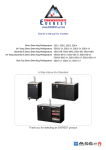
Oakley Sound Systems
Stereo Ensemble – SE330
PCB Issue 1
User Manual
V1.0.2
Tony Allgood
Oakley Sound Systems
CARLISLE
United Kingdom
Introduction
This is the User Manual for the issue 1 Stereo Ensemble SE330 module from Oakley Sound.
This document contains an overview of the unit and goes into some detail regarding the
operation of the module. It also contains the calibration instructions.
For the Builder's Guide, which contains a basic introduction to the circuit board and a full
parts list for the components needed to populate the board, please visit the main project
webpage at:
http://www.oakleysound.com/se330.htm
For general information regarding where to get parts and suggested part numbers please see
our useful Parts Guide at the project webpage or http://www.oakleysound.com/parts.pdf.
For general information on how to build our modules, including circuit board population,
mounting front panel components and making up board interconnects please see our generic
Construction Guide at the project webpage or http://www.oakleysound.com/construct.pdf.
2
The Oakley Sound SE330
The Oakley SE330 is a 'mono in, stereo out' ensemble unit designed to mimic the behaviour of
the multichannel chorus and ensemble units of late 1970s and early 1980s. The SE330 uses
four channels of bucket brigade delay (BBD) lines and four voltage controlled low frequency
oscillators (VC-LFO) to achieve a sound reminiscent of the Japanese string machines, guitar
chorus pedals and studio rack effects of yesteryear. Unlike the original devices the SE330
allows greater control over the modulation depths, speeds and waveforms, as well as featuring
a wet/dry control.
The SE330 features three basic modes:
Quad ensemble: All four delay lines are operating in this mode – with two BBDs and two
VC-LFOs being used for each stereo channel. This mode is at its most effective when the
wet/dry control is set to around 100% wet.
Stereo ensemble: In this mode two BBDs are being used, one per stereo channel. Each BBD
can be modulated by its own pair of VC-LFOs. This mode is very effective when the wet/dry
control is set to around 50%.
Dimension: Again, in this mode, two BBDs are being used. But this time both BBDs are
being driven from the same pair of VC-LFOs. However, one of the BBDs will receive the
inverted outputs of the VC-LFO pair. Like mode 2, this mode is very effective when the
wet/dry control is set to around 50%.
The four VC-LFOs are made from four separate circuits. Two of the LFOs produce sine
waves and two of them produce triangle waves. The SE330 is wired so that each stereo
channel's BBDs are controlled by one set of triangle and sine wave LFOs. Each pair of similar
waveform VC-LFOs are controlled by one set of speed and depth pots. So one set of pots
controls the two sine wave LFOs and one set controls the two triangle wave LFOs. Each pair
of similar waveform LFOs will therefore track each other but one is set to always run 20%
faster than the other.
An effective compander circuit reduces the inevitable noise created by the analogue delay lines
to a respectable level. A peak LED lights when the input signal is getting too big and
noticeable distortion would result.
Input and output level control pots are also provided to allow maximum flexibility in dealing
with a variety of input signal levels. Both the input and output connections are balanced but
can be used with unbalanced connections if desired.
The power to the unit should be a regulated split supply of +/-12V to +/-17V. Power is
admitted onto the main circuit board via a four way 0.156” (2.96mm) header of MTA or KK
type. The module can be powered by our own Rack Power Supply Unit (RPSU) or any other
MOTM compatible supply such as the Oakley PSU . Power consumption is +140mA and
-110mA at +/-15V
The printed circuit board size is 198mm (width) x 234mm (depth).
3
Operating Instructions
INPUT LEVEL
The input level should be set so that the peak LED never lights continuously. The brighter the
LED shines the more you are overdriving the unit and this is generally to be avoided. Ideally,
the peak LED should never come on in normal operation. Once the input level is set to the
correct point then the output level control can be adjusted to suit.
PEAK LED
This gives a visual indication of when the signal being sent to the delay line circuitry exceeds
the recommended amount. As soon as the LED starts to glow the delay line circuitry will be
close to clipping and distorting. The level required to clip the delay lines varies with frequency
and the harmonic content of the signal. Brighter sounds, or ones of very high pitch, are more
likely to clip than low frequencies. For example; a static sine wave at 200Hz will clip at 3.6V
peak-peak. While at 2kHz clipping will start at 1.2V peak to peak.
TRIANGLE RATE
Controls the rate of the triangle wave low frequency oscillator (LFO). An LFO produces an
output signal that changes in voltage with a repeatable and periodic shape. The triangle wave
output rises at a constant rate, reaches an apex and then descends at the same rate as it went
up. Then at its lowest point it rises again and the process repeats itself. It is called a triangle
wave because when viewed on an oscilloscope the trace is made from a series of triangles.
TRIANGLE DEPTH
Controls the depth of the triangle wave modulation. The deeper the modulation the greater the
change in delay times the BBD lines exhibit. Quick changes in delay are heard as a change in
pitch by the listener. With a triangle wave the pitch changes can be quite severe as the
waveform changes direction.
4
SINE RATE
Controls the rate of the sine wave LFOs. A sine wave is similar to the triangle wave but the
rises and falls in output voltage are more gentle. The waveform is more akin to natural
resonances slowing down before it changes direction.
SINE DEPTH
Controls the depth of the sine wave modulation. Sine waves produce a more natural sounding
pitch change when they modulate a BBD.
BALANCE
This adjusts the mix between the unaffected signal and the one coming from the delay line or
lines. DRY is the unaffected signal while WET is the delayed signal.
MODE SWITCH
This sits between the two right most pots and is key to understanding what the modulation
section of the SE330 does. It has three positions; dimension, stereo and quad.
There are four bucket brigade delay lines in the SE330. Each side of the stereo signal has two
dedicated BBDs and each BBD has its own driver circuitry which controls the delay imparted
by the BBD. These driver circuits are modulated with low frequency oscillators. Thus each
LFO can alter the delay time exhibited by the BBD it controls.
There are four LFOs in the SE330 but they are not connected so that one LFO controls its
own BBD. This should work well but in practice it doesn't give the sound of the classic
Japanese string machines and effects units that we want to hear. So the SE330 does something
much more complicated and, in doing so, can mimic most of the well known ensembles units
of the past.
Dimension Mode
This is the simplest of the SE330's three modes. Only two BBD lines are used in this mode,
one for the left hand channel and one for the right. The mono input is shared equally to each
BBD's input. Each BBD produces a similar delay when not modulated so that the sound from
both left and right is more or less the same. Two LFOs, one whose output is a triangle wave,
the other, whose output is a sine wave, are used as modulation sources. The rate and depth of
each LFO is controllable from the front panel controls. Both BBDs are modulated by the sum
of both LFOs. That is, both LFOs control both BBDs together. However, there is one
important difference between the modulating signals that are sent to each BBD. The BBD that
affects the right hand side operates inversely to the left hand one. So that when the delay of
the left hand BBD is increasing, the right hand one is decreasing.
5
When listened to dry the overall effect is like an odd form of panning and vibrato at the same
time. But when the balance pot is turned to around 50% a subtle chorus sound is heard.
Stereo Ensemble Mode
This mode is similar to the dimension mode but features four LFOs and not just two. Instead
of the right hand BBD being modulated by the inverse of the same LFOs that control the left
hand side, this time the right hand BBD gets its own pair of triangle and sinewave LFOs.
However, these LFOs are not completely independent of the left hand side ones. The rate and
frequency controls are shared with the left hand LFOs. Therefore the right hand side LFOs
will track the frequency and amplitude of the left hand side LFOs. The only difference between
the two sides are that the right hand side LFOs always run 20% faster than the left hand side.
This keeps things relatively stable across the stereo panorama, yet, because of the free running
nature of all four LFOs, things are different enough between the channels to give a wide
ensemble sound.
Quad Ensemble Mode
The RS or VP ensemble mode. The third mode is the most complex. The basic behaviour is
the same as the stereo mode, but the quad mode adds an extra BBD line to each stereo
channel. This additional BBD is only controlled by the triangle LFO and not the sine wave
LFO. However, it responds inversely to the other BBD on its channel. So as the other BBD is
increasing in delay, the extra one is decreasing. And because it doesn't respond to the sine
wave LFO, the output of the BBD can be very different to the other BBD on the same
channel. This creates a rich rolling sound. The classic RS or VP string sound involves only the
effected sound, ie. 100% wet. The triangle wave LFOs being set to fairly slow (one cycle
around 5 seconds) but deep modulations. And then with a much smaller amount of faster
(around 5Hz) sine wave modulation added.
POWER LED
This will light when power is applied to the unit. To be precise, it lights when the positive
power supply rail is up and running.
OUTPUT LEVEL
This adjusts the output level of the unit. The gain of the whole module is +6dB when being
driven with an unbalanced audio signal.
6
Input and Output Connections
The SE330 has both balanced input and output connections. It is expected that the unit will be
fitted with three pole TRS (tip-ring-sleeve) sockets. Both input and output are compatible
with unbalanced signals and mono jack plugs can be used without detriment to the SE330
It should work fine with signal levels direct from a mixer, line level synthesisers and modular
synthesisers. The input impedance is too low to work direct from guitars unless they are fitted
with internal pre-amplifiers.
The maximum input signal level without clipping the pre-amplifier stage is +/-12V if the
SE330 has a +/-15V internal supply. Signal levels higher than +/-30V have the potential to
damage the unit. Input impedance is 44K. Output impedance is 220R.
7
Calibration
There are sixteen trimmers on the SE330. It will be useful to have access to an oscilloscope
and a frequency counter for the calibration routine, however, it is not necessary as most
adjustments can be done with just your ears and a voltmeter.
All voltages should be measured with respect to a suitable 0V point. That is the black lead of
your meter should be connected to 0V. 0V is most easily found at the cathode of D18 – the
end that is nearest to the power header.
CLK1 This sets the delay time of BBD line number 1.
If you have no scope or frequency counter then adjust CLK1 so that pin 1 of U12 is
approximately 3.30V.
If you have access to a scope or frequency counter then measure the signal at pin 6 of U6.
Adjust CLK1 so that the frequency of the square wave is approximately 75kHz.
CLK2 This sets the delay time of BBD line number 2.
If you have no scope or frequency counter then adjust CLK2 so that pin 1 of U32 is
approximately 3.30V.
If you have access to a scope or frequency counter then measure the signal at pin 6 of U17.
Adjust CLK2 so that the frequency of the square wave is approximately 75kHz.
CLK3 This sets the delay time of BBD line number 3.
If you have no scope or frequency counter then adjust CLK3 so that pin 7 of U26 is
approximately 3.30V.
If you have access to a scope or frequency counter then measure the signal at pin 6 of U6.
Adjust CLK3 so that the frequency of the square wave is approximately 75kHz.
CLK4 This sets the delay time of BBD line number 4.
If you have no scope or frequency counter then adjust CLK4 so that pin 7 of U32 is
approximately 3.30V.
If you have access to a scope or frequency counter then measure the signal at pin 6 of U35.
Adjust CLK1 so that the frequency of the square wave is approximately 75kHz.
8
OFF1, OFF2, OFF3 & OFF4 These adjust the bias point of the respective BBD line's input
signal. If this voltage offset is set too high or too low then the output signal of that BBD will
distort too easily.
Input a triangle wave or smooth sounding tone into the SE330. You can use a keyboard and
hold down the A key to give you a constant 440Hz tone. Try not to make it too bright and
don't use a square wave. Adjust the input level so that the peak LED is just starting to glow
dimly. Turn down both modulation depth pots and set the balance pot to wet. Select
dimension mode.
Listen to the left output of the SE330 only and adjust OFF2 so that the sound is not distorting.
There will be a point at which the sound is not distorting noticeably while either side of it
sounds thinner and grubbier.
Now select quad mode. The sound from the left channel will be louder. Adjust OFF1 until the
sound is not distorting noticeably.
Listen to the right hand output only and select dimension mode again. Adjust OFF4 so that the
sound is not distorting.
Now select quad mode. Adjust OFF3 until the sound is not distorting noticeably.
NULL1, NULL2, NULL3 & NULL4 These adjust the amount of high frequency clock
breakthrough into the audio output. You want to set these so that the smallest amount of
clock is getting through to the output.
If you have no scope then just set this trimmer to its middle position. Although this sounds
pretty imprecise it's actually not too far from the perfect setting.
If you have access to a scope you can tweak it more exactly. Set your scope's time base to
5uS per division and the scaling to 200mV per division. Immediately below the TL072 op-amp
in each delay section on the PCB there is a small ceramic capacitor. For BBD1 this is C17.
Just below this capacitor is a resistor. It's not clear which resistor this is as its name is
underneath it – it's actually R19 for BBD1. The left hand pad of this resistor is the point you
need to measure for each BBD. Adjust the relevant NULL trimmer so that the waveform
amplitude seen on the scope trace is minimised. Set incorrectly you'll see a kind of spiky
square wave. Set correctly the trace will reduce to just a series of spikes. Do this for all four
BBD lines.
T_FRQ This sets the frequency range of the triangle LFOs. Insert an audio input into the
SE330. The A440 note is a good one to use again. Set the triangle rate and triangle depth pot
to their middle settings. Set the sine wave pots to their minimum. Select the dimension mode
and turn the balance control to wet. Make sure the peak LED is not lit and listen to the left
output only. You should hear the pitch being modulated. Adjust T_FRQ so that you hear the
dee-dah sound repeating once a second.
9
If you have a 'scope, monitor the voltage at pin 1 of U3. Set the triangle rate pot to its
maximum value and adjust T_FRQ until you get a 50Hz triangle wave.
T_LVL This sets the maximum output level of both triangle wave LFOs. Without a 'scope this
is difficult to set exactly but it doesn't really matter that much. Simply adjust the trimmer to its
middle position and you should find that the depth pot goes from nothing to all out freaky
vibrato.
If you do have a 'scope then set the triangle rate and depth pots to their maximum. Then
monitor the voltage on pin 1 of U11 and adjust T_LVL until you get a 10V peak to peak
signal.
S_FRQ This sets the frequency range of the sine wave LFOs. Insert an audio input into the
SE330. The A440 note is a good one to use again. Set the sine rate and sine depth pot to their
middle settings. Set the triangle wave depth pots to their minimum. Select the dimension mode
and turn the balance control to wet. Make sure the peak LED is not lit and listen to the left
output only. You should hear the pitch being modulated again but much more smoothly than
with the triangle wave LFO. Adjust S_FRQ so that you hear a ee-aw sound repeating once a
second.
If you have a 'scope, monitor the voltage at pin 1 of U22. Set the sine rate pot to its maximum
value and adjust T_FRQ until you get a 50Hz sine wave.
T_LVL This sets the maximum output level of both sine wave LFOs. Without a 'scope this is
difficult to set exactly but it doesn't really matter that much. Simply adjust the trimmer to its
middle position and you should find that the depth pot goes from nothing to all out freaky
vibrato.
If you do have a 'scope then set the triangle rate and depth pots to their maximum. Then
monitor the voltage on pin 1 of U31 and adjust T_LVL until you get a 10V peak to peak
signal.
10
Final Comments
I hope you enjoy using the Oakley Sound SE330.
If you have any problems with the module, an excellent source of support is the Oakley Sound
Forum at Muffwiggler.com.
If you have a comment about this user manual, or have a found a mistake in it, then please do
let me know either via e-mail or the forum.
Tony Allgood at Oakley Sound
Cumbria, UK
© August 2013
No part of this document may be copied by whatever means without my permission.
11