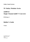
1
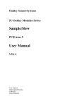
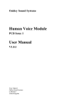
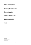
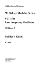
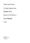
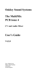
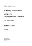
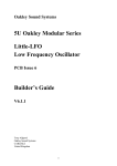
Oakley Sound Systems
5U Oakley Modular Series
Multimix issue 5
Four channel mixer with reversible attenuators
Builder's Guide
V5.0.02
Tony Allgood B.Eng
Oakley Sound Systems
CARLISLE
United Kingdom
Introduction
This is the Project Builder's Guide for the issue 5 Multimix 5U module from Oakley Sound.
This document contains a basic introduction to the board, a full parts list for the components needed
to populate the board, interconnections and some basic testing methods.
For the User Manual, which contains an overview of the operation of the unit, advice on connecting
the unit and calibration procedures, please visit the main project webpage at:
http://www.oakleysound.com/multimix.htm
For general information regarding where to get parts and suggested part numbers please see our
useful Parts Guide at the project webpage or http://www.oakleysound.com/parts.pdf.
For general information on how to build our modules, including circuit board population, mounting
front panel components and making up board interconnects please see our generic Construction
Guide at the project webpage or http://www.oakleysound.com/construct.pdf.
The issue 5 Multimix PCB
The prototype Multimix 5 in a natural finish Schaeffer panel. Note the use of the PCB that holds the sockets. This
is an early Sock6 board with reduced input and outputs. Newer builds use our Sock8 or Sock8 Wide Boy PCBs.
I have provided space for the three main control pots on the PCB. If you use the specified 16mm
Alpha pots and matching brackets, the PCB can be held firmly to the panel without any additional
mounting procedures. The pot spacing is 1.625” and is the same as the vertical spacing on the
MOTM modular synthesiser and most of our other modules.
The design requires plus and minus 15V supplies. The power supply should be adequately
regulated. The current consumption is about 35mA for the positive rail and 30mA for the negative
rail. Power is routed onto the PCB by a four way 0.156” MTA156 type connector or the special five
way Synthesizers.com MTA100 header. You could, of course, wire up the board by soldering on
wires directly. The four pins are +15V, ground, earth/panel ground, -15V. The earth/panel
connection allows you to connect the metal front panel to the power supply’s ground without it
sharing the modules’ ground line. More about this later.
The PCB has four mounting holes for M3 bolts, one near each corner. These are not required if you
are using the two 16mm pot brackets.
The board size is 104mm (high) x 112mm (deep).
The board has been laid out to accept connection to our Sock8 socket board. This small board
speeds up the wiring of the eight sockets and reduces the chances of mistakes. Sock8 is available in
both standard size or 'wide boy' size for Synthesizers.com compatible panels.
Parts List
For general information regarding where to get parts and suggested part numbers please see our
useful Parts Guide at the project webpage or http://www.oakleysound.com/parts.pdf.
The components are grouped into values, the order of the component names is of no particular
consequence.
A quick note on European part descriptions. R is shorthand for ohm. K is shorthand for kilo-ohm. R
is shorthand for ohm. So 22R is 22 ohm, 1K5 is 1,500 ohms or 1.5 kilohms. For capacitors: 1uF =
one microfarad = 1000nF = one thousand nanofarad.
To prevent loss of the small ‘.’ as the decimal point, a convention of inserting the unit in its place is
used. eg. 4R7 is a 4.7 ohm, 4K7 is a 4700 ohm resistor, 6n8 is a 6.8 nF capacitor.
Resistors
All resistors should be 0.25W 5% carbon or better. Parts labelled MF should 0.25W or 0.4W 1%
metal film types.
To save confusion with different colour codes I recommend all resistors be 0.25W or 0.4W 1% MF
types.
22R
75R
120R
470R
3K
3K3
3K9
10K
11K
22K MF
24K MF
33K
47K
100K MF
470K
1M
3M3
R51
R5, R16, R45, R44
R41 This sets the brightness of both LEDs. Increase this
value to reduce brightness.
R43
R36
R9
R33
R1, R4, R21, R22, R8, R20
R30
R29, R37, R34, R6, R40, R38, R35, R32, R13, R2, R31, R39,
R46
R49, R50, R48, R7, R47, R3, R15
R10
R14, R12
R24, R27, R25, R28, R23, R26
R19, R17, R18
R11
R42
Capacitors
100nF axial multilayer ceramic
1uF, 63V radial electrolytic
22uF, 35V radial electrolytic
2u2,63V radial electrolytic
C18, C19, C11, C2, C4, C15, C9, C3, C14, C13, C10, C5, C8,
C12
C7
C22
C16, C17
33pF ceramic 2.5mm
C1, C21, C20, C6
Discrete Semiconductors
1N4148
BC560 PNP transistor
Green LED 5mm
Red LED 5mm
D1, D2, D3, D4, D5
Q1
LED2 – mounted off board
LED1 – mounted off board
Integrated Circuits
TL072 dual FET op-amp
LM2903 dual comparator
U1, U2, U3, U4, U5, U7, U8
U6
IC sockets are recommended. You need eight 8-pin DIL sockets.
Potentiometers
47K linear Alpha 16mm
LEVEL1, LEVEL2, LEVEL3
Two Alpha pot brackets are also required. The LEVEL1 pot has no bracket.
Miscellaneous
Leaded Ferrite beads
Knobs to fit 6mm shafts
L1, L2
Three off
Molex or MTA 4 way header
MTA100 6-way header
PSU – Oakley/MOTM power supply
PWR – Synthesizers.com power supply
Molex/MTA 0.1” header 6-way
Molex/MTA 0.1” header 8-way
Molex/MTA 0.1” housing 6-way
Molex/MTA 0.1” housing 8-way
UPPER – for connecting to sockets
LOWER – for connecting to sockets
UPPER – for connecting to sockets
LOWER – for connecting to sockets
Molex/MTA 0.1” housing 2-way
LED1, LED2
1/4” sockets
Eight off mounted either on the Sock8 board or on panel
Hook up wire (26awg).
Wire Links
You will also need three 2cm long pieces of solid core wire to make the three links on the board.
The actual position of these links determines how the three level controls work, either as a simple
level control or as a reversible attenuator. The links can be made from component leg clippings or
uninsulated tinned copper wire. Simply solder a small hoop of the wire joining the relevant pads of
each link. For each of the ‘three pad links’, LK1, 2 & 3, pad 1 is the square pad at one end, pad 3 is
middle pad, and pad 2 is the round pad on the end.
If the Multimix is to be built with three reversible attenuators (the 'Stooge' variant) then each of the
three links need to have pads 1 and 3 linked. That is the middle pad to the square pad.
If the Multimix is to be built with three standard level controls (the 'Sum' variant) then each of the
three links need to have pads 2 and 3 linked. That is the middle pad to the end round pad.
The link LK2 configured in 'Stooge' mode with pads 1 and 3 linked together.
Additional components required if using optional Sock8 board
Molex/MTA 0.1” header 6-way
Molex/MTA 0.1” header 8-way
Molex/MTA 0.1” housing 6-way
Molex/MTA 0.1” housing 8-way
UPR
LWR
UPR
LWR
112APCX Switchcraft 1/4” socket SK1, SK2, SK3, SK4, SK5, SK6, SK7, SK8
If using Molex KK you'll also need at least 28 crimp terminals.
Suitable lengths of wire to make up the two interconnects and three cable ties.
Wire Link
You also need to fit a wire link into the location on the Sock8 PCB marked as L1. This ensures that
the NC lug on the IN4 socket is grounded.
Connections
Power connections – MOTM and Oakley
The PSU power socket is 0.156” Molex/MTA 4-way header. Friction lock types are recommended.
This system is compatible with MOTM systems.
Power
Pin number
+15V
Module GND
Earth/PAN
-15V
1
2
3
4
Pin 1 on the LWR header has been provided to allow the ground tags of the jack sockets to be
connected to the powers supply ground without using the module’s 0V supply. Earth loops cannot
occur through patch leads this way, although screening is maintained. Of course, this can only work
if all your modules follow this principle.
Power connections – Synthesizers.com
The PWR power socket is to be fitted if you are using the module with a Synthesizers.com system.
In this case you should not fit the PSU header. The PWR header is a six way 0.1” MTA, but with
the pin that is in location 2 removed. In this way location 3 is actually pin 2 on my schematic,
location 4 is actually pin 5 and so on.
Power
Location number
Schematic Pin number
+15V
Missing Pin
+5V
Module GND
-15V
Not connected
1
2
3
4
5
6
1
2
3
4
5
+5V is not used on this module, so location 3 (pin 2) is not actually connected to anything on the
PCB.
If fitting the PWR header, you will also need to link out pins 2 and 3 of the PSU header. This
connects the panel ground with the module ground. Simply solder a solid wire hoop to join the two
middle pads of PSU together.
Building the Multimix 5 module using the Sock8 board
This is the simplest way of connecting all the sockets to the main board. The Sock8 board should be
populated in the way described in our construction guide found on the project webpage. There are
only two headers, UPR (for upper) which is six way, and LWR (for lower) which is eight way. Both
headers are fitted to the bottom side of the board.
You need to make up two interconnects. The six way one should be made so that it is 80mm long.
The eight way should be made to be 130mm.
The prototype SVF issue 5 module showing the detail of the board to board interconnects. The Multimix is wired
similarly. Here I have used the Molex KK 0.1” system to connect the Sock8 to the main PCB.
Building the Multimix 5 module by wiring the sockets manually
If you have bought Switchcraft 112A sockets you will see that they have three connections. One is
the earth or ground tag. One is the signal tag which will be connected to the tip of the jack plug
when it is inserted. The third tag is the normalised tag, or NC (normally closed) tag. The NC tag is
internally connected to the signal tag when a jack is not connected. This connection is automatically
broken when you insert a jack.
Once fitted to the front panel the ground tags of each socket can be all connected together with solid
wire. I use 0.91mm diameter tinned copper wire for this job. It is nice and stiff, so retains its shape.
A single piece of insulated wire can then be used to connect those connected earth tags to pin 1 of
LWR. Pin 1 is the square solder pad.
All the other connections are shown in the tables below:
UPPER
Pin
Pad name
Socket Connection
Lug Type
Pin 1
Pin 2
Pin 3
Pin 4
Pin 5
Pin 6
OUT2
NC2
NC1
OUT1
module ground
IN1
Connect to OUT2
Connect to OUT2
Connect to OUT1
Connect to OUT1
Connect to IN1 & IN2
Connect to IN1
Signal lug
NC lug
NC lug
Signal lug
NC lugs
Signal lug
LOWER
Pin
Pad name
Socket Connection
Lug Type
Pin 1
Pin 2
Pin 3
Pin 4
Pin 5
Pin 6
Pin 7
Pin 8
Panel ground
MIX+
IN4
OUT3/MIX
module ground
IN2
module ground
IN3
Connects to all sockets
Connect to MIX OUT
Connect to IN4
Connect to OUT3/MIX
Connect to IN3
Connect to IN2
Connect to IN4
Connect to IN3
Ground lugs via wire frame
Signal lug
Signal lug
Signal lug
NC lug
Signal lug
NC lug
Signal lug
Light Emitting Diodes
The 5V LED fitted to the panel with a translucent green cliplite. A two way Molex KK housing is used to make the
connection to the LED device. This allows the LED to be removed easily.
Both LEDs are wired to the board via flying wires. I twist the wires and cable tie them together to keep them neat.
The cathode of the LED is connected to the round pad on the board.
Testing, testing, 1, 2, 3...
Apply power to the unit making sure you are applying the power correctly. Check that no device is
running hot. Any sign of smoke or strange smells turn off the power immediately and recheck the
polarity of the power supply, and the direction of the ICs in their sockets.
Assuming everything is OK so far, it is time to apply an audio input. Use a bright signal like a
sawtooth output from a VCO. Middle A, 440Hz is a good note to use.
Connect up an amplifier or mixing desk input to the OUT3/MIX socket. Now connect your signal to
the first input. You should be control the level with the top pot. If you have built the Stooge version,
you should be able to silence the input by moving the pot to its middle position. If you have built
the Sum version, the pot should act as an ordinary volume control.
Input channels two and three should perform identically
Now listen to the output coming from MIX OUT. This should behave much like the OUT3/MIX
socket, but it should also be able to pass any signal connected to IN4. Connect your VCO to IN4
and check you can hear the VCO's output through MIX OUT. None of the level pots should have an
affect on the level of the signal coming into IN4.
If you are using a modular VCO as a source for your input signal, check that the green LED turns
on when the input level is turned to its maximum. The LEDs track the output signal coming from
the MIX OUT socket. The green LED will turn on when the signal level reaches over +/-5V which
should be obtained when the input level is fully clockwise (and also fully anti-clockwise in the case
of the Stooge variant). You should note that the actual trigger value does depend a little on input
wave shape and frequency. The red LED only turns on when the output level exceeds +/-11V. To
test this function on your modular the easiest thing to do is use two VCOs, each one going to a
separate input on the Multimix. With two sawtooth input signals, and both their level controls set to
maximum, the peak LED should light in time with the audible beating of the two VCOs. If your
LEDs fail to light make sure you haven't reversed the connections to the LEDs.
Another way to check the LED's operation is to use a voltage source. The Oakley midiDAC is an
excellent source of voltage that can be used to test the Multimix. Simply connect the modulation
wheel output to IN1 and turn its level pot fully up. Then as you rotate the mod wheel on your
controller the midiDAC will put out an increasing positive voltage. At just under half way it will
put out around 5V and the green LED should light. Fully up the midiDAC will be producing 10.6V
and this should be easily enough to tickle the RED LED to light.
You should now check the output from OUT1 and OUT2. OUT1 should be a pot controlled version
of IN1, and OUT2 should be a pot controlled version of IN2. Inserting a jack plug into either OUT1
or OUT2 will cut the respective input from the OUT3/MIX socket, but not from the MIX OUT
socket. The MIX OUT socket will always sum IN1, IN2, IN3 and IN4 together regardless of any
jack plugs inserted into OUT 1, OUT2 or OUT3/MIX.
Final Comments
If you have any problems, an excellent source of support is the Oakley Sound Forum at
Muffwiggler.com. Paul Darlow and I are on this group, as well as many other users and builders of
Oakley modules.
If you can't get your project to work, then Oakley Sound Systems are able to offer a 'get you
working' service. If you wish to take up this service please e-mail me, Tony Allgood, at my contact
e-mail address found on the website. I can service either fully populated PCBs or whole modules.
You will be charged for all postage costs, any parts used and my time at 25GBP per hour. Most
faults can be found and fixed within one hour, and I normally return modules within a week. The
minimum charge is 25GBP plus return postage costs.
If you have a comment about this builder's guide, or have a found a mistake in it, then please do let
me know. But please do not contact me or Paul Darlow directly with questions about sourcing
components or general fault finding. Honestly, we would love to help but we do not have the time
to help everyone individually by e-mail.
Last but not least, can I say a big thank you to all of you who helped and inspired me. Thanks
especially to all those nice people on the Synth-diy, Oakley-Synths and Analogue Heaven mailing
lists and those at Muffwiggler.com.
Tony Allgood at Oakley Sound
Cumbria, UK
© July 2010
Updated October 2010
No part of this document may be copied by whatever means without my permission.