1
Part 20 - Checking the SCIO Interface
The SCIO interface contains the digital interface device, a microprocessor and connects
together the necessary cabling. The power for the LED’s (lights) originates from the USB
connection, which draws on computer power. LED’s have a very long life and generally do
not fail. If a LED does not illuminate as below check connections first. If the lights are not
functioning, there may be a problem with the computer settings (and not with the device).
Check that the UAC is turned off (as explained in Part 13.2 above) and check that the COM
port settings are correct (as explained in Part 16 above). If there is a LED issue then the
device may be be sent to an authorized Service Center listed under Policies & Procedure in
the Service Center Policy.
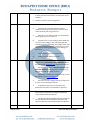
Power on: All LED’s will flash briefly and there will be an audible beep when the SCIO is
powered on.
Program Opening: a SCIO found message will display.
Calibration: all illuminate, with Rx and Tx having intermittent operation.
Test: all except Tx illumines.
Therapy: The daVinci and channel LED’s will illuminate continuously with the Rx and Tx
illuminating at intervals.
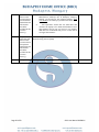
Green LED (power): will display when
The SCIO is connected to the computer by the USB cable
The SCIO is switched on (rear of unit)
LED Integrity
All LED’s will flash briefly when the SCIO is powered on.
Rx and Tx LED’s
Rx (receiving) indicated that signals are being sent to the client.
Tx (transmitting) indicates that client transmissions are being monitored: signals are being
received from the client.
The Rx and Tx LED’s will flash briefly:
1
On power up
2
When the SCIO has been found by the program on opening.
Red Channel 1-8 LED’s
Page 35 of 63
SCIO User Manual 200003-K