1
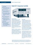
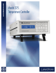
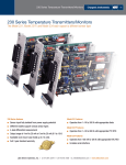
86 Instruments Model 340 Temperature Controller Model 340 Temperature Controller Features Operates down to 100 mK with appropriate NTC RTD sensors Two sensor inputs; expandable to ten sensor inputs Supports diode, RTD, capacitance, and thermocouple sensors Sensor excitation current reversal eliminates thermal EMF errors Two autotuning control loops: 100 W and 1 W IEEE-488 and RS-232C interfaces, analog outputs, digital I/O, and alarm relays www.lakeshore.com Product Description The Model 340 is our most advanced temperature controller and offers unsurpassed resolution, accuracy, and stability for temperature measurement and control applications to as low as 100 mK. Operating with diodes, platinum RTDs, and negative temperature coefficient (NTC) resistor sensors, the Model 340 is expandable to ten sensor inputs or to operate with thermocouple or capacitance sensors. It has two control loops, with the first loop powered to 100 W. Sensor Inputs The Model 340 features two inputs with high-resolution 24-bit analog-to-digital converter and low noise circuit design, providing temperature readings with resolution as low as 0.1 mK at 4.2 K. Sensors are optically isolated from other instrument functions for quiet and repeatable sensor measurements. Lake Shore Cryotronics, Inc. (614) 891-2244 Appropriate sensor excitation and input gain can be selected from the front panel. An autorange mode keeps the power in NTC resistors low to reduce selfheating as sensor resistance changes by many orders of magnitude. Automatic current reversal with rounded square wave excitation for NTC resistors eliminates the effect of thermal EMF. Standard temperature response curves for silicon diodes, platinum RTDs, and many thermocouples are included. Up to twenty 200-point CalCurves™ for Lake Shore calibrated sensors or user curves can be loaded into non-volatile memory via a computer interface or the instrument front panel. CalCurves™ can be installed at the factory when purchased with a Model 340, or they can be field installed using the data card slot. A built-in SoftCal™1 algorithm can also be used to generate curves for silicon diodes and platinum RTDs, for storage as user curves. 1 The Lake Shore SoftCal™ algorithm for silicon diode and platinum RTD sensors is a good solution for applications that need more accuracy than a standard sensor curve but do not warrant traditional calibration. SoftCal™ uses the predictability of a standard curve to improve the accuracy of an individual sensor around a few known temperature reference points. fax: (614) 818-1600 e-mail: [email protected] Model 340 Temperature Controller Temperature Control The Model 340 offers two proportional-integral-derivative (PID) control loops. A PID control algorithm calculates control output based on temperature setpoint and feedback from the control sensor. Wide tuning parameters accommodate most cryogenic cooling systems and many small high-temperature ovens. Control output is generated by a high-resolution digital-toanalog converter for smooth continuous control. The user can manually set the PID values or the autotuning feature of the Model 340 can automate the tuning process. The main heater output for the Model 340 is a well-regulated variable DC current source. Heater output is optically isolated from other circuits to reduce interference and ground loops. Heater output can provide up to 100 W of variable DC power to control Loop 1. Features have been added to the Model 340 to minimize the possibility of overheating delicate sensors and wiring in cryostats. These features include setpoint temperature limit, heater current range limit, internal heater diagnostics, and a fuse in the heater output wiring. The Model 340 also has the ability to run a second independent control loop, intended to reduce the temperature gradients in one cooling system rather than to run two different cooling systems. The setpoint ramp feature allows smooth, continuous changes in setpoint. This feature permits faster experiment cycles, since data can be taken as the system is changing in temperature. It can also be used to make a more predictable approach to a setpoint temperature. The zone feature can automatically change control parameter values for operation over a large temperature range. Values for ten different temperature zones can be loaded into the instrument, which will select the next appropriate zone value on setpoint change. b f b - Line Input Assembly c - Heater Fuse d - Heater Output e - Option Slots www.lakeshore.com c g Instruments The Model 340 can run a set of instrument instructions called an internal program. Each program represents the temperature changes needed to conduct a user’s experiment. The setpoint can be changed or ramped up and down, and other controller parameters can be programmed. For simple experiments the internal program eliminates the need for computer control. It is also common for the internal program to be used along with the computer interface so the computer is not slowed down by temperature control overhead. Several math features are included to improve usability and aid in setting up experiments. It is often useful to have reading filters and maximum and minimum calculations easily available on the front panel. The Model 340 also computes a linear equation on reading data to allow flexibility in how the display represents experimental inputs. Interface The Model 340 can be fully involved in computer-controlled experiments. It is equipped with IEEE-488 and RS-232C interfaces. Either interface can send settings to the Model 340 and collect reading data from it. Even the analog outputs, relays, and Digital I/O can be controlled by computer interface. The Model 340 has several features to make it more valuable as part of a larger measuring system. Two analog voltage outputs can be used to report a voltage that is proportional to the temperature of an input. The outputs can be controlled manually as a voltage source for any other application. Two relays can be used with the alarm setpoints in latching mode for error detection, or in nonlatching mode for simple on and off control. Digital I/O can be used with an external scanner or manually. d h e i f - Data Card g - IEEE-488 Interface h - Serial (RS-232C) I/O i - Digital I/O Lake Shore Cryotronics, Inc. 87 (614) 891-2244 j 1) 1! j - Relays 1) - Analog Outputs 1! - Standard Sensor Inputs fax: (614) 818-1600 e-mail: [email protected] 88 Instruments Model 340 Temperature Controller Additional Inputs Available For Model 340 Configurable Display The Model 340 includes a graphic LCD with fluorescent backlight display that is fully configurable and can display up to eight readings. The following optional inputs are available for the Model 340. Only one can be installed at a time, and the standard inputs stay in the instrument and remain fully functional. Calibration for the option is stored on the card so it can be installed in the field without recalibration. 3462 Dual Standard Input Option Card Adds two standard inputs to the Model 340, appearing on the display as C and D. The card has separate A/Ds and excitation for each sensor. A microprocessor on the card manages the A/D and communication with the Model 340. Allows the Model 340 to read four sensors and use any of them as a control sensor. This shows a variation of the display with a large loop 1 heater output graphic bar where the PID parameters are not displayed, but the heater output is more prominent. The user can display 1 to 8 readings from any of the available inputs. The units available are the sensor units of mV, V, Ω, kΩ, nF, or temperature units of °C or K. Results of the math feature can also be selected. The user can select the sensor type, and the controller will automatically select the sensor units, excitation, and range. If ‘special’ type is selected, the user can choose any available excitation and input range. 3464 Dual Thermocouple Input Option Card Adds two new thermocouple inputs to the Model 340, appearing on the display as C and D. The card has separate A/Ds and excitation for each sensor. A microprocessor on the card manages the A/D and communication with the Model 340. Thermocouple inputs range from cryogenic temperature to 1000 °C, with built-in room temperature compensation. Curves for thermocouple types E, K, and AuFe 0.07% vs. Cr are included. The user can add other types. 3465 Single Capacitance Input Option Card Adds a new capacitance input to the Model 340, appearing on the display as C. The card has separate A/D and excitation for the sensor. A microprocessor on the card manages the A/D and communication with the Model 340. The 3465 is intended to control temperature in strong magnetic fields using a Lake Shore Model CS-501 capacitance temperature sensor. 3468 Eight Channel Input Option Card Adds eight sensor inputs to the Model 340. The optional inputs are broken into two groups of four and appear on the display as C1–C4 for Input C, D1–D4 for Input D. The 3468 includes two A/D converters, one for each group of four inputs, and individual excitation for each sensor. Each input group must use the same sensor type, but the two groups can be different. The multiplexed inputs provide new readings for all eight inputs twice each second. The 3468 inputs are not recommended for temperature control because the reading rate is too slow to allow good stability. A variety of sensor types are supported by the Model 3468, but not as many as the standard inputs. Diode and platinum configurations have similar specifications to the standard inputs, reduced only slightly to account for multiplexing. However, the NTC RTD configuration is quite different than the standard inputs. The option has a limited resistance range of 7.5 kΩ with a fixed current excitation of 10 µA. This limitation significantly reduces the low temperature range of the inputs. The option also does not support current reversal to reduce the effect of thermal EMF voltages. The original standard inputs remain fully functional allowing the Model 340 to measure 10 sensors when the option is installed. www.lakeshore.com Lake Shore Cryotronics, Inc. (614) 891-2244 fax: (614) 818-1600 e-mail: [email protected] Model 340 Temperature Controller Instruments 89 Sensor Temperature Range (sensors sold separately) Diodes 340/3462 Positive Temperature Coefficient RTDs 340/3462 Negative Temperature Coefficient RTDs 340/3462 Thermocouples 3464 Capacitance 3465 Diodes 3468 Positive Temperature Coefficient RTDs 3468 Negative Temperature Coefficient RTDs2 3468 Silicon Diode Silicon Diode Silicon Diode Silicon Diode Silicon Diode Silicon Diode GaAlAs Diode GaAlAs Diode GaAlAs Diode 100 Ω Platinum 100 Ω Platinum Rhodium-Iron Rhodium-Iron Cernox™ Cernox™ Cernox™ Cernox™ Cernox™ Germanium Germanium Germanium Germanium Germanium Germanium Germanium Germanium Carbon-Glass Carbon-Glass Carbon-Glass Rox™ Rox™ Rox™ Type K Type E ChromelAuFe 0.07% Silicon Diode Silicon Diode Silicon Diode Silicon Diode Silicon Diode Silicon Diode GaAlAs Diode GaAlAs Diode GaAlAs Diode 100 Ω Platinum 100 Ω Platinum Rhodium-Iron Rhodium-Iron Cernox™ Cernox™ Cernox™ Cernox™ Cernox™ Germanium Germanium Germanium Carbon-Glass Carbon-Glass Carbon-Glass Rox™ www.lakeshore.com Model Useful Range Magnetic Field Use DT-670-SD DT-670E-BR DT-414 DT-421 DT-470-SD DT-471-SD TG-120-P TG-120-PL TG-120-SD PT-102/3 PT-111 RF-800-4 RF-100T/U CX-1010 CX-1030-HT CX-1050-HT CX-1070-HT CX-1080-HT GR-200A-30 GR-200A-50 GR-200A-100 GR-200A-250 GR-200A/B-500 GR-200A/B-1000 GR-200A/B-1500 GR-200A/B-2500 CGR-1-500 CGR-1-1000 CGR-1-2000 RX-102 RX-103 RX-202 9006-006 9006-004 1.4 K to 500 K 30 K to 500 K 1.4 K to 375 K 1.4 K to 325 K 1.4 K to 500 K 10 K to 500 K 1.4 K to 325 K 1.4 K to 325 K 1.4 K to 500 K 14 K to 873 K 14 K to 673 K 1.4 K to 500 K 1.4 K to 325 K 0.3 K to 325 K3 0.3 K to 420 K3, 5 1.4 K to 420 K3 4 K to 420 K3 20 K to 420 K3 0.1 K to 5 K5 0.2 K to 40 K5 0.3 K to 100 K 0.5 K to 100 K 1.4 K to 100 K 1.4 K to 100 K 1.4 K to 100 K 1.4 K to 100 K 1.4 K to 325 K 1.7 K to 325 K4 2 K to 325 K4 0.1 K to 40 K5 1.4 K to 40 K 0.1 K to 40 K5 3.2 K to 1505 K 3.2 K to 934 K T ≥ 60 K & B ≤ 3 T T ≥ 60 K & B ≤ 3 T T ≥ 60 K & B ≤ 3 T T ≥ 60 K & B ≤ 3 T T ≥ 60 K & B ≤ 3 T T ≥ 60 K & B ≤ 3 T T > 4.2 K & B ≤ 5 T T > 4.2 K & B ≤ 5 T T > 4.2 K & B ≤ 5 T 9006-002 CS-501 1.2 K to 610 K 1.4 K to 290 K Not Recommended DT-670-SD DT-670E-BR DT-414 DT-421 DT-470-SD DT-471-SD TG-120-P TG-120-PL TG-120-SD PT-102/3 PT-111 RF-800-4 RF-100T/U CX-1010 CX-1030-HT CX-1050-HT CX-1070-HT CX-1080-HT GR-200A/B-1000 GR-200A/B-1500 GR-200A/B-2500 CGR-1-500 CGR-1-1000 CGR-1-2000 RX-102A 1.4 K to 500 K 30 K to 500 K 1.4 K to 375 K 1.4 K to 325 K 1.4 K to 500 K 10 K to 500 K 1.4 K to 325 K 1.4 K to 325 K 1.4 K to 500 K 14 K to 800 K 14 K to 673 K 1.4 K to 500 K 1.4 K to 325 K 2 K to 325 K5 3.5 K to 420 K3,6 4 K to 420 K3,6 15 K to 420 K3 50 K to 420 K3 2.2 K to 100 K4 2.6 K to 100 K4 3.1 K to 100 K4 4 K to 325 K5 5 K to 325 K5 6 K to 325 K5 1.4 K to 40 K5 T ≥ 60 K & B ≤ 3 T T ≥ 60 K & B ≤ 3 T T ≥ 60 K & B ≤ 3 T T ≥ 60 K & B ≤ 3 T T ≥ 60 K & B ≤ 3 T T ≥ 60 K & B ≤ 3 T T > 4.2 K & B ≤ 5 T T > 4.2 K & B ≤ 5 T T > 4.2 K & B ≤ 5 T Lake Shore Cryotronics, Inc. T > 40 K & B ≤ 2.5 T T > 40 K & B ≤ 2.5 T T > 77 K & B ≤ 8 T T > 77 K & B ≤ 8 T T > 2 K & B ≤ 19 T T > 2 K & B ≤ 19 T T > 2 K & B ≤ 19 T T > 2 K & B ≤ 19 T T > 2 K & B ≤ 19 T Not Recommended Not Recommended Not Recommended Not Recommended Not Recommended Not Recommended Not Recommended Not Recommended T > 2 K & B ≤ 19 T T > 2 K & B ≤ 19 T T > 2 K & B ≤ 19 T T > 2 K & B ≤ 10 T T > 2 K & B ≤ 10 T T > 2 K & B ≤ 10 T Silicon diodes are the best choice for general cryogenic use from 1.4 K to above room temperature. Diodes are economical to use because they follow a standard curve and are interchangeable in many applications. They are not suitable for use in ionizing radiation or magnetic fields. Cernox™ thin-film RTDs offer high sensitivity and low magnetic field-induced errors over the 0.3 K to 420 K temperature range. Cernox sensors require calibration. Platinum RTDs offer high uniform sensitivity from 30 K to over 800 K. With excellent reproducibility, they are useful as thermometry standards. They follow a standard curve above 70 K and are interchangeable in many applications. 2 Single excitation current may limit the low temperature range of NTC resistors 3 Non-HT version maximum temperature: 325 K 4 Low temperature limited by input resistance range 5 Low temperature specified with self-heating error: ≤ 5 mK 6 Low temperature specified with self-heating error: ≤ 12 mK Not Recommended Not Recommended Not Recommended T > 40 K & B ≤ 2.5 T T > 40 K & B ≤ 2.5 T T > 77 K & B ≤ 8 T T > 77 K & B ≤ 8 T T > 2 K & B ≤ 19 T T > 2 K & B ≤ 19 T T > 2 K & B ≤ 19 T T > 2 K & B ≤ 19 T T > 2 K & B ≤ 19 T Not Recommended Not Recommended Not Recommended T > 2 K & B ≤ 19 T T > 2 K & B ≤ 19 T T > 2 K & B ≤ 19 T T > 2 K & B ≤ 10 T (614) 891-2244 fax: (614) 818-1600 e-mail: [email protected] 90 Instruments Model 340 Temperature Controller Sensor Selection Typical Sensor Performance – see Appendix F for sample calculations of typical sensor performance Example Lake Shore Sensor Temp Nominal Resistance/ Voltage Typical Sensor Sensitivity7 Measurement Resolution: Temperature Equivalents Electronic Accuracy: Temperature Equivalents Temperature Accuracy including Electronic Accuracy, CalCurve™, and Calibrated Sensor Electronic Control Stability8: Temperature Equivalents Silicon Diode DT-670-CO-13 with 1.4H calibration Silicon Diode DT-470-SD-13 with 1.4H calibration GaAlAs Diode TG-120-SD with 1.4H calibration 1.4 K 77 K 300 K 500 K 1.4 K 77 K 300 K 475 K 1.4 K 77 K 300 K 475 K 30 K 77 K 300 K 500 K 0.3 K 0.5 K 4.2 K 300 K 1.4 K 4.2 K 77 K 420 K 0.5 K 1.4 K 4.2 K 100 K 1.4 K 4.2 K 10 K 100 K 1.4 K 4.2 K 77 K 300 K 0.5 K 1.4 K 4.2 K 40 K 75 K 300 K 600 K 1505 K 4.2 K 77 K 200 K 1.664 V 1.028 V 0.5597 V 0.0907 V 1.6981 V 1.0203 V 0.5189 V 0.0906 V 5.391 V 1.422 V 0.8978 V 0.3778 V 3.660 Ω 20.38 Ω 110.35 Ω 185.668 Ω 2322.4 Ω 1248.2 Ω 277.32 Ω 30.392 Ω 26566 Ω 3507.2 Ω 205.67 Ω 45.03 Ω 29570 Ω 1376 Ω 198.9 Ω 2.969 Ω 8257 Ω 520 Ω 88.41 Ω 1.751 Ω 103900 Ω 584.6 Ω 14.33 Ω 8.55 Ω 3701 Ω 2005 Ω 1370 Ω 1049 Ω -5862.9 µV 1075.3 µV 13325 µV 49998.3 µV 6 nF 9.1 nF 19.2 nF -12.49 mV/K -1.73 mV/K -2.3 mV/K -2.12 mV/K -13.1 mV/K -1.92 mV/K -2.4 mV/K -2.22 mV/K -97.5 mV/K -1.24 mV/K -2.85 mV/K -3.15 mV/K 0.191 Ω/K 0.423 Ω/K 0.387 Ω/K 0.378 Ω/K -10785 Ω/K -2665.2 Ω/K -32.209 Ω/K -0.0654 Ω/K -48449 kΩ/K -1120.8 kΩ/K -2.4116 Ω/K -0.0829 Ω/K -221000 Ω/K -2220 Ω/K -68.9 Ω/K -0.025 Ω/K -19400 kΩ/K -245 kΩ/K -19.5 Ω/K -0.014 Ω/K -520000 Ω/K -422.3 Ω/K -0.098 Ω/K -0.0094 Ω/K -5478 Ω/K -667 Ω/K -80.3 Ω/K -1.06 Ω/K 15.6 µV/K 40.6 µV/K 41.7 µV/K 36.006 µV/K 27 pF/K 52 pF/K 174 pF/K 0.8 mK 5.8 mK 4.4 mK 4.8 mK 0.8 mK 5.2 mK 4.2 mK 4.5 mK 0.1 mK 8.1 mK 3.6 mK 3.2 mK 5.3 mK 2.4 mK 2.6 mK 2.7 mK 3 µK 12 µK 94 µK 15 mK 6 µK 90 µK 1.3 mK 12 mK 14 µK 140 µK 440 µK 40 mK 52 µK 410 µK 515 µK 72 mK 58 µK 24 µK 3.1 mK 32 mK 19 µK 45 µK 375 µK 29 mK 26 mK 10 mK 10 mK 12 mK 7.4 mK 3.9 mK 1 mK ±13 mK ±76 mK ±47 mK ±40 mK ±13 mK ±69 mK ±45 mK ±38 mK ±7 mK ±180 mK ±60 mK ±38 mK ±13 mK ±10 mK ±34 mK ±55 mK ±0.2 mK ±0.5 mK ±6.2 mK ±540 mK ±0.4 mK ±3.4 mK ±68 mK ±520 mK ±0.2 mK ±0.9 mK ±3.8 mK ±200 mK ±0.6 mK ±3.0 mK ±5.6 mK ±270 mK ±0.6 mK ±1.2 mK ±140 mK ±1.1 K ±0.7 mK ±2.4 mK ±16 mK ±1.1 K ±0.124 K ±0.038 K ±0.184 K ±0.73 K ±2.08 K ±1.14 K ±0.4 K ±25 mK ±98 mK ±79 mK ±90 mK ±25 mK ±91 mK ±77 mK ±88 mK ±19 mK ±202 mK ±92 mK ±88 mK ±23 mK ±22 mK ±57 mK ±101 mK ±3.7 mK ±5 mK ±11.2 mK ±580 mK ±5.4 mK ±8.4 mK ±84 mK ±585 mK ±4.5 mK ±4.9 mK ±7.8 mK ±216 mK ±4.6 mK ±7 mK ±10.6 mK ±286 mK ±4.6 mK ±5.2 mK ±165 mK ±1.2 K ±5.2 mK ±7.4 mK ±32 mK ±1.2 K Calibration not available from Lake Shore ±1.6 mK ±11.6 mK ±8.8 mK ±9.6 mK ±1.6 mK ±10.4 mK ±8.4 mK ±9 mK ±0.2 mK ±16.2 mK ±7.2 mK ±6.4 mK ±10.6 mK ±4.8 mK ±5.2 mK ±5.4 mK ±6 µK ±24 µK ±188 µK ±30 mK ±12 µK ±180 µK ±2.6 mK ±24 mK ±28 µK ±280 µK ±880 µK ±80 mK ±104 µK ±820 µK ±1.03 mK ±114 mK ±116 µK ±48 µK ±6.2 mK ±64 mK ±38 µK ±90 µK ±750 µK ±58 mK ±52 mK ±20 mK ±20 mK ±24 mK ±14.8 mK ±7.8 mK ±2 mK 340/3462 100 Ω Platinum RTD 500 Ω Full Scale PT-103 with 14J calibration Cernox™ CX-1010-SD with 0.3L calibration Cernox™ CX-1050-SD-HT9 with 1.4M calibration Germanium GR-200A-250 with 0.5D calibration Germanium GR-200A-500 with 0.5D calibration Carbon-Glass CGR-1-500 with 1.4L calibration Rox™ RX-102A-AA with 0.3B calibration Thermocouple 50 mV 3464 Capacitance 150 nF 3465 Type K CS-501GR Calibration not available from Lake Shore 7 Typical sensor sensitivities were taken from representative calibrations for the sensor listed Control stability of the electronics only, in an ideal thermal system 9 Non-HT version maximum temperature: 325 K 8 www.lakeshore.com Lake Shore Cryotronics, Inc. (614) 891-2244 fax: (614) 818-1600 e-mail: [email protected] Model 340 Temperature Controller Instruments 91 Specifications Input Specifications Diode 340/3462 PTC RTD 340/3462 NTC RTD 1 mV 340/3462 NTC RTD 10 mV 340/3462 Thermocouple 3464 Capacitance 3465 Sensor Temperature Coefficient Input Range Excitation Current Display Resolution Measurement Resolution Electronic Accuracy Electronic Control Stability 10 negative negative positive positive positive negative negative negative negative negative negative negative negative negative negative negative negative negative negative negative negative negative positive positive positive or negative 0 V to 2.5 V 0 V to 7.5 V 0 Ω to 250 Ω 0 Ω to 500 Ω 0 Ω to 2500 Ω 0 Ω to 10 Ω 0 Ω to 30 Ω 0 Ω to 100 Ω 0 Ω to 300 Ω 0 Ω to 1 kΩ 0 Ω to 3 kΩ 0 Ω to 10 kΩ 0 Ω to 30 kΩ 0 Ω to 30 Ω 0 Ω to 100 Ω 0 Ω to 300 Ω 0 Ω to 1 kΩ 0 Ω to 3 kΩ 0 Ω to 10 kΩ 0 Ω to 30 kΩ 0 Ω to 100 kΩ 0 Ω to 300 kΩ ±25 mV ±50 mV 0 nF to 150 nF 10 µV 10 µV 1 mΩ 1 mΩ 10 mΩ 100 µΩ 100 µΩ 1 mΩ 1 mΩ 10 mΩ 10 mΩ 0.1 Ω 0.1 Ω 100 µΩ 1 mΩ 1 mΩ 10 mΩ 10 mΩ 0.1 Ω 0.1 Ω 1Ω 1Ω 0.1 µV 0.1 µV 10 pF 10 µV 10 µV 1 mΩ 1 mΩ 10 mΩ 1 mΩ 3 mΩ 10 mΩ 30 mΩ 0.1 Ω 0.3 Ω 1Ω 3Ω 300 µΩ 1 mΩ 3 mΩ 10 mΩ 30 mΩ 0.1 Ω 0.3 Ω 3Ω 30 Ω 0.2 µV 0.4 µV 2.0 pF ±80 µV ±0.005% of rdg ±80 µV ±0.01% of rdg ±0.002 Ω ±0.01% of rdg ±0.002 Ω ±0.01% of rdg ±0.03 Ω ±0.02% of rdg ±0.02% rng ±0.1% rdg ±0.02% rng ±0.1% rdg ±0.02% rng ±0.1% rdg ±0.02% rng ±0.1% rdg ±0.02% rng ±0.1% rdg ±0.02% rng ±0.1% rdg ±0.02% rng ±0.1% rdg ±0.02% rng ±0.1% rdg ±0.02% rng ±0.05% rdg ±0.02% rng ±0.05% rdg ±0.02% rng ±0.05% rdg ±0.02% rng ±0.05% rdg ±0.02% rng ±0.05% rdg ±0.02% rng ±0.05% rdg ±0.02% rng ±0.05% rdg ±0.02% rng ±0.05% rdg ±0.02% rng ±0.25% rdg ±1 µV ±0.05% of rdg ±1 µV ±0.05% of rdg ±50 pF ±0.1% of rdg 20 µV 20 µV 2 mΩ 2 mΩ 20 mΩ 2 mΩ 6 mΩ 20 mΩ 60 mΩ 0.2 Ω 0.6 Ω 2Ω 6Ω 600 µΩ 2 mΩ 6 mΩ 20 mΩ 60 mΩ 0.2 Ω 0.6 Ω 6Ω 60 Ω 0.4 µV 0.8 µV 4.0 pF positive or negative 0 nF to 15 nF 1 pF 0.2 pF ±50 pF ±0.1% of rdg 0.4 pF negative negative positive positive positive negative 0 V to 2.5 V 0 V to 7.5 V 0 Ω to 250 Ω 0 Ω to 500 Ω 0 Ω to 5000 Ω 0 Ω to 7500 Ω 10 µA ±0.05% 10 µA ±0.05% 1 mA 1 mA 0.1 mA 100 µA 30 µA 10 µA 3 µA 1 µA 300 nA 100 nA 30 nA 300 µA 100 µA 30 µA 10 µA 3 µA 1 µA 300 nA 100 nA 30 nA NA NA 4.88 kHz 1 V square wave 4.88 kHz 1 V square wave 10 µA ±0.01% 10 µA ±0.01% 1 mA ±0.3% 1 mA ±0.3% 1 mA ±0.3% 10 µA ±0.01% 100 µV 100 µV 10 mΩ 10 mΩ 100 mΩ 100 mΩ 20 µV 20 µV 2 mΩ 2 mΩ 20 mΩ 50 mΩ ±160 µV ±0.01% of rdg ±160 µV ±0.02% of rdg ±0.004 Ω ±0.02% of rdg ±0.004 Ω ±0.02% of rdg ±0.06 Ω ±0.04% of rdg ±0.01 Ω ±0.04% of rdg 40 µV 40 µV 4 mΩ 4 mΩ 40 mΩ 0.1 Ω Diode 3468 PTC RTD 3468 NTC RTD 3468 10 Control stability of the electronics only, in an ideal thermal system Sensor Input Configuration Thermometry Number of inputs Input configuration 2 included (additional inputs optional) Each input is factory configured as diode/RTD. Thermocouple and capacitance are optional and sold as additional input cards. Isolation Sensor inputs optically isolated from other circuits but not from each other A/D resolution 24-bit analog-to-digital Input accuracy Sensor dependent – refer to Input Specifications table Measurement resolution Sensor dependent – refer to Input Specifications table Maximum update rate Up to 20 readings per s on an input, 40 readings per s on all inputs Autorange Automatically selects appropriate NTC RTD range User curves Forty 200-point CalCurves™, or user curves SoftCal™ Improves accuracy of DT-470 diode or platinum RTD sensors Math Maximum and minimum of input readings and linear equation Filter Averages input readings to quiet display, settable time constant www.lakeshore.com Lake Shore Cryotronics, Inc. Diode/RTD Thermocouple Capacitance 4-lead differential 2-lead, room temperature compensated 4-lead Excitation Constant current with current reversal for RTDs NA 4.88 kHz, 1 V square wave Supported sensors Diodes: Silicon, GaAlAs RTDs: 100 Ω Platinum, 1000 Ω Platinum, Germanium, Carbon-Glass, Cernox™,and Rox™ Most thermocouple types CS-501GR Standard curves DT-470, DT-500D, DT-670, PT-100, PT-1000, RX-102A, RX-202A Type E, Type K, Type T AuFe 0.07% vs. Cr, AuFe 0.03% vs. Cr, None Input connector 6-pin DIN Ceramic isothermal block 6-pin DIN Measurement type (614) 891-2244 fax: (614) 818-1600 e-mail: [email protected] 92 Instruments Model 340 Temperature Controller Control Front Panel Control loops Control type 2 Closed-loop digital PID with manual heater power output, or open loop Autotune (one loop at a time), manual PID, zones Sensor dependent – to 2× measurement resolution (in an ideal thermal system) Tuning Control stability PID control settings Proportional (gain) Integral (reset) Derivative (rate) Manual output Zone control Setpoint ramping Safety limits 0 to 1000 with 0.1 setting resolution 1 to 1000 with 0.1 setting resolution 1 to 1000 s with 1 s resolution 0 to 100% with 0.01% setting resolution 10 temperature zones with P, I, D, manual heater power out, and heater range 0.1 K per min to 100 K per min Setpoint limit, curve temp limits, heater output, slope limit, heater range limit, power up heater off, and short-circuit protection Heater Output Specifications Heater output type Loop 1 Loop 2 Variable DC current source Variable DC voltage Heater output D/A resolution 18-bit 14-bit Max heater power 100 W 1W Max heater output current 2A 0.1 A Heater output compliance 50 V 10 V Heater source impedance NA 0.01 Ω Heater output ranges 5 decade steps in power 1 Heater load type Resistive Resistive Heater load range 10 Ω to 100 Ω recommended 100 Ω minimum Heater load for max power 25 Ω 100 Ω Heater noise (<1 kHz) RMS 50 µV + 0.001% of output voltage <0.3 mV Optical isolation between output and other circuits None Dual banana BNC Isolation Heater connector Loop 1 Full Scale Heater Power at Typical Resistance Heater Resistance Heater Range 2A 10 Ω 5 4 3 2 1 40 W 4W 0.4 W 40 mW 4 mW 10 W 1W 100 mW 10 mW 1 mW 2.5 W 250 mW 25 mW 2.5 mW 250 µW 625 mW 62.5 mW 6.25 mW 625 µW 62.5 µW 25 Ω 5 4 3 2 1 100 W 10 W 1W 100 mW 10 mW 25 W 2.5 W 250 mW 25 mW 2.5 mW 6.25 W 625 mW 62.5 mW 6.25 mW 625 µW 1.56 W 156 mW 15.6 mW 1.56 mW 156 µW 50 Ω 5 4 3 2 1 50 W 20 W 2W 200 mW 20 mW 50 W 5W 500 mW 50 mW 5 mW 12.5 W 1.25 W 125 mW 12.5 mW 1.25 mW 3.12 W 312 mW 31.2 mW 3.12 mW 312 µW www.lakeshore.com Maximum Current 1A 0.5 A Lake Shore Cryotronics, Inc. 0.25 A Display No. of reading displays Display units Temp display resolution Sensor units display resolution Setpoint setting resolution Heater output display Graphic LCD with fluorescent backlight 1 to 8 Temperature in K, °C, or sensor units 0.0001 K below 10 K, 0.001 K above 10 K Sensor dependent, to 6 digits Same as display resolution (actual resolution is sensor dependent) Numeric display in percent of full scale for power or current – bar graph display of heater output available Heater output resolution 0.1% numeric or 2% graphical Keypad Numeric plus special function Front panel features Front panel curve entry, display brightness control, and keypad lock-out Interfaces IEEE-488.2 interface Features Reading rate Software support Serial interface Electrical format Max baud rate Connector Reading rate Alarms Number Data source Settings SH1, AH1, T5, L4, SR1, RL1, PP0, DC1, DT0, C0, E1 To 20 readings per s National Instruments LabVIEW™ driver RS-232C 19,200 baud RJ-11 To 20 readings per s Two, high and low, for each installed input Temperature, Sensor Units, and Linear Equation Source, High and Low Setpoint, Latching or Non-Latching, and Audible On/Off Display, annunciator, beeper, and relays Actuators Relays Number 2 Contacts Normally open (NO), normally closed (NC), and common Contact Rating 30 VDC at 2 A Operation Activate relays on high or low alarms for any input, or manual off/on Connector Detachable terminal block Analog voltage outputs (when not used as control loop 2 output) Number 2 Scale User selected Update rate 20 readings per s Data source Temperature, Sensor Units, and Linear Equation Settings Input, Source, Top of Scale, Bottom of Scale, or Manual Range ±10 V Resolution 1.25 mV Max output power 1 W Min load resistance 100 Ω (short-circuit protected) Source impedance 0.01 Ω Digital I/O 5 inputs and 5 outputs – TTL voltage level compatible Data card PC card Type II slot used for curve transfer, setup storage, and data-logging General Ambient temp range Power requirements Size Weight Approval (614) 891-2244 20 °C to 30 °C (68 °F to 86 °F) for specified accuracy; 15 °C to 35 °C (59 °F to 95 °F) for reduced accuracy 100, 120, 220, 240 VAC (+5%, -10%), 50 or 60 Hz; 190 VA 432 mm W × 89 mm H × 368 mm D (17 in × 3.5 in × 14.5 in), full rack 8 kg (17.6 lb) approx. CE mark fax: (614) 818-1600 e-mail: [email protected] Model 340 Temperature Controller Extending Temperature Controller Heater Power It is often necessary to extend the heater power of a cryogenic temperature controller to conduct experiments above room temperature. This diagram illustrates a practical way to increase the control output of the Model 340 to several hundred watts. A programming resistor, Rpgm, is placed across the controller's heater output current source. As the heater output current changes, a changing voltage is generated across Rpgm. That voltage is used to program a large external power supply. Rpgm should be chosen so that a low current range of the controller can be used. The control output of loop 2 on the Model 340 is a voltage, thus it can be connected directly to the external power supply without Rpgm. 3003 Heater Output Conditioner The heater output conditioner is a passive filter which further reduces the already low Model 340 heater output noise. The typical insertion loss for the Model 3003 is 20 dB at or above line frequency, and >40 dB at or above double line frequency. A 144 mm W × 72 mm H × 165 mm D (5.7 in × 2.8 in × 6.5 in) panel mount enclosure houses this option, and it weighs 1.6 kg (3.5 lb). www.lakeshore.com Lake Shore Cryotronics, Inc. Instruments 93 Ordering Information Part number Description 340 2 diode/resistor inputs temperature controller Select a power configuration*: VAC-100 Instrument configured for 100 VAC with U.S. power cord VAC-120 Instrument configured for 120 VAC with U.S. power cord VAC-120-ALL Instrument configured for 120 VAC with U.S. power cord and universal Euro line cord and fuses for 220/240 VAC setting VAC-220 Instrument configured for 220 VAC with universal Euro line cord VAC-240 Instrument configured for 240 VAC with universal Euro line cord *Other country line cords available, consult Lake Shore Accessories included 106-009 Heater output connector (dual banana jack) 106-233 Two sensor mating connector 6-pin DIN plugs used for sensor inputs 106-737 6-pin terminal block used for relays connector – accepts up to 12 AWG wire 2001 4-wire RJ11 cable assembly, 4.6 m (14 ft) long, used with RS-232C interface 2003 RJ11 to DE-9 adapter – adapts RJ11 receptacle to female DE-9 connector; connects Model 340 to customer computer rear RS-232C serial port —— Calibration certificate MAN-340 Model 340 user manual Options and accessories 2002 RJ11 to DB-25 adapter 2003 RJ11 to DE-9 adapter 3003 Heater output conditioner 3462 2-channel card for additional standard sensors 3464 2-channel card for thermocouple sensors 3465 1-channel card for capacitance sensors 3468 8-channel scanner card for silicon diodes, PTC and NTC RTD sensors 3507-2SH Cable assembly for 2 sensors and 1 heater 8001-340 CalCurve™, factory installed – the breakpoint table from a calibrated sensor stored in the instrument 8072 IEEE-488 computer interface interconnect cable assembly CAL-340-CERT Instrument calibration with certificate HTR-25 25 Ω, 25 W cartridge heater HTR-50 50 Ω, 50 W cartridge heater RM-1 Rack mounting kit (614) 891-2244 fax: (614) 818-1600 e-mail: [email protected]