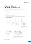
1
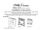
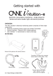
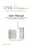
Getting started with
Electricity consumption & Solar PV generation monitoring
– single phase, for homes fitted with Solar PV
IN THE BOX:
Transmitter unit
3 channel
2 x plug-in standard
Sensor clamp
(<10mm cable, <71A)
3 x AA
alkaline battery
x2
PART NO. CMA113
MADE IN CHINA
1. Measuring CAT II
2. Max. voltage 250V ~
3. Max. current 71 Amp
© 2 Save Energy Limited 2014
1
Introduction
This Electricity Transmitter is a part of the OWL Intuition range of cloud connected monitoring and control products. Its operation is dependant upon being paired to the broadband Internet connected Network OWL (supplied separately).
This version of the Electricity Transmitter is designed for monitoring single phase electricity consumption and Solar PV generation. It is suitable for use in homes and some smaller
light commercial premises.
Access to both live and historic energy information collected by this Transmitter is via the
OWL Intuition web dashboard, from any Internet connected computer anywhere in the
World. iPhone and Android smartphone apps are also available for free download.
For details on using your new OWL Intuition-pv system, please download the Electricity
Monitoring User Manual document by clicking on Manuals on the web dashboard (lower
right).
2
© 2 Save Energy Limited 2014
Installation Instructions
BEFORE YOU START - Determine PV System Type
Intuition-pv will NOT work correctly unless the correct wiring configuration has been identified and the 2 or 3 Sensor clamps are correctly installed.
Intuition-pv Type 1 (solar PV - Henley block)
The standard Intuition-pv package is only suitable for a Type 1 wiring configuration where
the PV generation feed is connected to the properties existing mains wiring via a Henley
Junction Block. Please refer to wiring diagram on page 4 to identify if this installation is a
Type 1 configuration.
Intuition-pv Type 2 (solar PV - Consumer unit)
If the PV generation feed is connected to the properties existing mains wiring via a circuit
breaker or fuse within your main Consumer Unit / Fuse Box then this is a Type 2 wiring
configuration. Please refer to wiring diagram on page 5 to identify if this installation is a
Type 2 configuration. IMPORTANT: If you have a Type 2 wiring configuration you MUST
also purchase a Y-Cable Pack (Part Number: TSE200-010). This includes a third Sensor
clamp and a “Y-Cable”.
© 2 Save Energy Limited 2014
3
Type 1 Intuition-pv (solar PV - Henley block)
Transmitter & Sensor Installation
Grid-tie
Inverter
Transmitter
Solar PV
Array
DC
230V AC
50Hz
Domestic
Loads
PV
Generation
Sensor
Utility Meter
Fuse Box /
Consumer Unit
WARNING
- RISK OF ELECTRICAL SHOCK
- Please Refer to User Manual.
WARNING
- RISK OF ELECTRICAL SHOCK
- Please Refer to User Manual.
Ring Mains,
Lights,
Cooker etc
Electricity
Grid
Henley
Junction Block
Normal Convention with Live cable to Consumer Unit
being the right most cable connected to the Meter
(Brown or Red normally covered with Grey sheath)
4
Consumption Sensor
© 2 Save Energy Limited 2014
Type 2 Intuition-pv (solar PV - Consumer unit)
Transmitter & Sensor Installation
Transmitter
PV Gen Sensor 1
Orientation of this
clamp is not
important
1. Measuring CAT II
2. Max. voltage 250V ~
3. Max. current 71 Amp
PART NO. CMA113
MADE IN CHINA
Y-Cable
Grid-tie
Inverter
DC
PV Gen Sensor 2
230V AC Important: Orient
50Hz
this clamp so that the
CE marking is facing
the inverter
1. Measuring CAT II
2. Max. voltage 250V ~
3. Max. current 71 Amp
WARNING
- RISK OF ELECTRICAL SHOCK
- Please Refer to User Manual.
Electricity
Grid
Normal Convention with Live cable to Consumer Unit
being the right most cable connected to the Meter
(Brown or Red normally covered with Grey sheath)
Domestic
Loads
Fuse Box /
Consumer Unit
PART NO. CMA113
MADE IN CHINA
Utility Meter
Solar PV
Array
Grid Sensor
Important: Orient
this clamp so that the
CE marking is facing
the grid supply
© 2 Save Energy Limited 2014
Ring Mains,
Lights,
Cooker etc
Y-Cable Pack
also required
5
STEP ONE - Install Network OWL
•
•
If you are adding PV monitoring to an existing Intuition installation then please jump
to STEP THREE - Log in and follow Wizard.
If this is a new Intuition installation then you will first need to install the Network OWL
(supplied separately). For full details please refer to the Network OWL installation
guide supplied with that product, however a summary of the steps are listed below:
1. Connect Ethernet cable between spare active LAN port on your broadband Internet router and the Network OWL.
2. Plug the power supply into the mains and insert the DC jack connector into the
base of the Network OWL.
3. Wait until the green LED on the top of the Network OWL is flashing with a “triple
blip” pattern. This should not normally take longer than 2 minutes.
4. Do NOT proceed to STEP TWO until this flashing pattern is observed.
STEP TWO - Create Intuition online account
•
•
If you are adding PV monitoring to an existing Intuition installation then please jump
to STEP THREE - Log in and follow Wizard.
If this is a new Intuition installation then you will first need to create a new OWL
Intuition account. For full details please refer to the Network OWL installation guide
supplied with that product, however a summary of the steps are listed below:
6
© 2 Save Energy Limited 2014
1.
2.
3.
4.
5.
6.
Using a web browser visit https://www.owlintuition.com
Click “Create Account”.
Check and confirm that the Network OWL is online.
Fill in the information requested.
Click “Create Account” button.
Ensure successful account creation completion message is displayed.
STEP THREE - Log in and follow Wizard
•
•
•
•
Log in to the OWL Intuition account with username and password.
If this is a new system the installation & configuration Wizard will
automatically open. For existing
Intuition installations you should
start the Wizard by clicking the
Wizard menu bar option at the top
of the screen.
Select “Electricity / Solar Monitoring”
from the drop down box.
Click the “Start” button and follow
the Wizard through these steps:
• Select Electricity Transmitter
© 2 Save Energy Limited 2014
7
•
•
•
type as “CMR180i” and click “Next”.
Slide back cover off of the Transmitter and insert the batteries into the unit.
Press the small “Check” button in the Transmitter battery compartment until the red LED on the front starts
flashing.
The Transmitter is now in Pairing / Check Mode and
PART NO. CMR180i
MADE IN CHINA
the red LED on the front will start flashing every 2 seconds (for 30 seconds). Click the Wizard “Next” button.
IMPORTANT Pairing Notes:
•
•
•
Please DO NOT remove the Transmitter batteries once fitted or the pairing will be lost.
• You can quickly check for correct pairing at any time
by pressing the Transmitter “Check” button until the
red LED starts flashing - if the Transmitter red LED
and Network OWL blue LED flash within a fraction of a
second of each other, they are correctly paired.
When the “Pairing Successful” message is displayed in the
PRESS
Wizard click “Next”.
CHECK BUTTON
Select Electricity Monitoring System type as either “Intuition-pv Type 1 (Solar PV - Henley block) OR “Intuition-pv Type 2 (Solar PV - Consumer
unit) to suit the wiring configuration used by this installation (see page 3 for details)
8
© 2 Save Energy Limited 2014
•
•
•
•
•
•
•
and click “Next”.
Adjust consumption Voltage and Power Factor settings to measured values if available.
If in doubt leave the default values (Voltage = 230; Power Factor = 1.0) and click
“Next”.
Configure the Solar Settings (Generation) settings to measured values / current meter
readings if available. If in doubt leave the default values (Voltage = 240; Power Factor
= 1.0).
Enter the PV System Rating (kW) and select the direction that the majority of the solar
panels are facing then click “Next”.
Ensure message “Device successfully added to your Intuition system.” is displayed.
Click the “Finish” button.
Unless you have further Intuition devices to install / configure then click the “Finish”
button.
Click the “OK” button to close the Wizard. The web dashboard will then automatically
refresh itself and you should now have an Electricity and Solar widget within the web
dashboard, although the live readings will be zero at this stage until the Sensors are
correctly attached in the next step.
© 2 Save Energy Limited 2014
9
STEP FOUR - Install Transmitter and attach Sensors
IMPORTANT:
• You must ensure that each Sensor is ONLY around the live core and NOT around a
sheathed cable containing live, neutral and earth.
• The Sensors must be a loose fit onto the cables.
• After the Sensors have been installed, the Transmitter should be hung on the wall in a
free area as far from large metal objects as possible.
In the section BEFORE YOU START on page 3 you will have determined whether you are
installing an Intuition-pv Type 1 (solar PV - Henley block) OR an Intuition-pv Type 2 (solar
PV - Consumer unit) system. Please now follow the relevant sub-section below, referring to
the diagrams on pages 4 and 5 as required.
Intuition-pv Type 1 (solar PV - Henley block)
• Consumption Sensor - Locate the supply cables between the Henley block and consumer unit (fuse box). Using the latch, clamp the first Sensor around the insulated
Live cable going into the consumer unit. Plug this Sensor into the Transmitter left hand
socket. The orientation of this Sensor is not important.
• Generation Sensor - Locate the PV generated power cable between the Henley block
and Generation meter / Inverter. Using the latch, clamp the second Sensor around the
insulated Live cable going into the Henley Block. Plug this Sensor into the Transmitter
centre socket. The orientation of this Sensor is not important.
10
© 2 Save Energy Limited 2014
Intuition-pv Type 2 (solar PV - Consumer unit)
•
•
•
•
PV Generation Sensor 1 - Locate the PV generated power cable between the inverter
and consumer unit (fuse box). Using the latch, clamp the first Sensor around the insulated Live cable going into the consumer unit. Plug this Sensor into the Transmitter
centre socket. The orientation of this Sensor is not important.
PV Generation Sensor 2 - For correct operation it is important that the CE mark
on this Sensor is oriented to face the Inverter end of the cable. Taking this
into account, using the latch, clamp this second Sensor around the same insulated
Live cable that PV Generation Sensor 1 is attached to. Plug this Sensor into either of
the arms of the Y-Cable.
Grid Sensor - Locate the supply cables between your electricity meter and consumer
unit (fuse box). For correct operation it is important that the CE mark on this
Sensor is oriented to face the electricity meter end of the cable. Taking this
into account, using the latch, clamp this third Sensor around the insulated Live cable
going into the consumer unit. Plug this Sensor into the remaining arm of the Y-Cable.
Y-Cable - With both Sensors attached, plug the Y-Cable into the Transmitter left-hand
socket.
Tip: Orient the Sensor clamps such that the CE
mark faces the direction the power is coming from.
© 2 Save Energy Limited 2014
11
STEP FIVE - Log in to your OWL Intuition account
If you are not already, please log in to your OWL Intuition account with your username
and password at: https://www.owlintuition.com
• You should now have an Electricity and Solar widget within your web dashboard.
• If you watch these new widgets, you should see the live consumption and generation
values updating every 12 to 60 seconds.
• Type 2 systems only - If when the Generation figure changes you see the Consumption figure change by a similar amount you need to reverse the direction the cable
is going through Grid Sensor. Undo the Sensor latch, remove, twist 180 degrees and
re-attach around the cable. If unclear please see web site Support for further information.
Consumption
•
Generation
Check the signal strength of the radio signal between your Transmitter and Network
OWL:
• If the signal strength is only 1 or 2 bars, to reduce the chance of intermittent /
inconsistent data reception it is suggested that you reposition the Network OWL
so that it is physically closer to the Transmitter.
12
© 2 Save Energy Limited 2014
Signal strength indicator
•
Settings icon
• The Network OWL should ideally be hung on the wall in a free area as far from
large metal objects as possible. Position the antenna in a vertical orientation.
• If necessary you can replace the Ethernet cable with a longer cable (up to 100
meters long). If installing a long Ethernet cable is a problem, you can use a
“Powerline Range Extender” or “Wireless Range Extender” - please search for
these common products online.
Click on the Electricity widget Settings icon - here you can set details of your electricity
tariff.
© 2 Save Energy Limited 2014
13
•
•
•
Click on the Solar widget Settings icon - here you can set details of your feed in /
export tariff.
For details on using your new OWL Intuition-pv system, please now download the
Electricity Monitoring User Manual document by clicking on Manuals on the web dashboard (lower right).
Please ensure you retain this document for future reference.
14
© 2 Save Energy Limited 2014
INFORMATION & TROUBLE SHOOTING TIPS
•
•
•
•
•
Unless the Transmitter is in Check Mode, the red LED does not flash, in order to prolong battery life.
Check that the blue LED on the Network OWL flashes at least every 12 seconds if the
monitored electricity supply consumption is varying, or every 60 seconds when at a
steady state.
For wireless range testing you can make the Transmitter send its signal every 2 seconds (for 30 seconds) by pressing the “Check” button in the battery compartment for
10 seconds. The red LED will flash with each transmission, the Network OWL blue LED
will flash to confirm the signal has been received.
If the blue LED does not flash then the Transmitter signal is not being received or the
Transmitter Pairing has been lost.
• On the web dashboard click on the Devices menu, then click on Electricity
Transmitter. If the Last Reported time is greater than 60 seconds then it is likely
the batteries have been removed from the Transmitter since pairing. Click on the
“Change Batteries” button and follow the instructions provided.
• If necessary undo the Transmitter’s Sensors and move it so it is close to the Network OWL. Repeat step above to confirm if radio range is an issue.
Battery change - when the Transmitter batteries require replacement the battery
icon on the Electricity widget will change to red. Use web dashboard Devices menu /
Electricity Transmitter / Change Batteries feature to ensure that pairing is not lost.
© 2 Save Energy Limited 2014
15
SAFETY INFORMATION
To ensure that you use your product safely and correctly please read the warnings & safety
precautions below before installing your OWL Intuition Transmitter & Sensor.
• This product uses a Type C current Sensor. Do not apply around or remove from hazardous LIVE conductors.
• When fitting the Sensor if in any doubt always contact a qualified electrician.
• Do not immerse the unit in water or other liquids. If you spill liquid over it, dry it immediately with a soft cloth.
• Do not use or store the product in conditions that could adversely affect the product
such as rain, snow, desert and magnetic fields.
• Do not subject the product to excessive force, shock, dust, temperature or humidity.
• Keep the product away from heat sources - radiators, stoves, heaters etc.
• Do not use the product in or near water or in high moisture areas such as bathrooms.
• Do not tamper with the product’s internal components. This invalidates the warranty.
• Do not attempt to repair the product yourself.
• Contact the retailer or Customer Services if your product requires servicing.
• If the equipment is used in a manner not specified in this manual, the protection provided by the equipment may be impaired.
• Take care when handling all battery types. Batteries can cause injuries, burns or damage to property if they come into contact with conducting materials, heat, corrosive
16
© 2 Save Energy Limited 2014
•
•
•
•
materials or explosives.
Remove the batteries before storing the product for extended periods.
Only use fresh batteries. Do not mix new and old batteries.
Do not dispose of old batteries as unsorted municipal waste, only do so in accordance
with your local waste disposal regulations.
When disposing of this product do so in accordance with your local waste disposal
regulations.
CARING FOR YOUR PRODUCT
•
•
•
•
Before cleaning, disconnect the Sensor and remove the batteries from the Transmitter.
Use a lightly dampened cloth. Do not use liquid or aerosol cleaning agents, benzene,
thinners, abrasive or corrosive materials.
Do not scratch hard objects against the product.
Do not leave discharged batteries in the product.
© 2 Save Energy Limited 2014
17
SPECIFICATIONS
Transmitter dimensions
64mm x 95mm x 40mm
Sensor dimensions (max when closed)
50mm x 50mm x 30mm
Radio frequency band
433MHz unlicenced ISM band
Operating range
Up to 30m (in free space)
Power source
3 x 1.5V Alkaline AA batteries
Operating temperature range
0°C to +40°C
Storage temperature range
-25°C to +65°C
Relative humidity
25% to 95% non-condensing
COMPLIANCE
The CE marking certifies that this product meets the main requirements of the European
Parliament and Council Directive 1999/5/EC. A copy of the signed and dated Declaration of
Conformity is available on request. OWL Intuition products are manufactured to ISO-9001
Quality Assurance Standards.
18
© 2 Save Energy Limited 2014
WARRANTY INFORMATION
2 Save Energy Limited guarantees that OWL Intuition products will work for a minimum
period of 24 months from date of purchase and that it will be free from defects in
materials, workmanship or design. If during this limited 2 year period of guarantee, from
date of purchase, you find that the equipment is not working properly, you may return it to
us and we will replace, or, (at our discretion) repair it, free of charge.
2 Save Energy Limited will not accept any liability for defects arising from fair wear and
tear, accidental or wilful damage, misuse or failure to follow product or safety instructions
If you return any equipment as faulty, 2 Save Energy Limited reserves the right to test the
equipment and if found to be in perfect working order, to return it to you. In this event, 2
Save Energy Limited reserves the right to charge for any testing or postage costs incurred.
This does not affect your legal rights relating to equipment, which is faulty. Warranty
conditions only apply where Proof of Purchase is provided.
To return your OWL Intuition product please contact [email protected] to
report the issue and your reason for wishing to return your product. 2 Save Energy Limited
will issue you an RMA number. You should ensure that the returned product is clearly
marked with the issued RMA number. Once we have received the product and proof of
purchase we will commence the returns process.
© 2 Save Energy Limited 2014
19
For details on using your new OWL Intuition-pv system, please download
the Electricity Monitoring User Manual document by clicking on Manuals on
the web dashboard (lower right).
Customer Support
If you have any further questions please check our knowledge base at:
https://theowl.zendesk.com
You can also email us at: [email protected]
(please ensure you state your Network OWL MAC ID)
2 Save Energy Limited operate a policy of continuous development and improvement,
therefore the content of this document is subject to change without notice.
Document Version 3.1 - June 2014
20
© 2 Save Energy Limited 2014