1
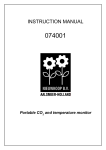
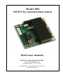
Model 305e
OEM CO2 concentration sensor
Reference manual
DIGITAL CONTROL SYSTEMS
7401 SW Capitol Hwy.
Portland, OR 97219 USA
503/246-8110 ♦ 503/246-6747 (fax)
www.dcs-inc.net
Revision History
Date
11/11/2005
3/16/2006
1/21/2007
3/8/2007
3/16/2008
3/11/2015
DCS Model 305e user’s manual
Table of Contents
Revision History .................................................................................. 2
Scope ................................................................................................... 4
Introduction ......................................................................................... 4
Specifications....................................................................................... 4
Mechanical........................................................................................... 5
Electrical Connections ......................................................................... 5
Operating Power ............................................................................... 5
Analog Measurement Output............................................................ 6
Digital Interface ................................................................................ 6
Operator Interface................................................................................ 7
Using Jumper Functions ................................................................... 7
Measurement Calibration (JP2) ........................................................ 8
Elevation Correction ......................................................................... 8
Relay Set Point.................................................................................. 9
Relay Hysteresis................................................................................ 9
Analog Calibration............................................................................ 9
Analog Output Offset Adj. (JP4 & JP3)...................................... 9
Analog Output Span Adj. (JP4 & JP5) ....................................... 9
Last Rev: 3/11/15
page 3 of 9
Digital Control Systems • 7401 SW Capitol Hwy • Portland, OR
97219 • 503/246-8110
DCS Model 305e user’s manual
Scope
This document applies to the –01 and higher circuit board revisions..
The part numbers 32-0133-01 or 32-0133-02 in the lower left hand
corner of the circuit board identifies these units.
Introduction
The DCS Model 305e is very compact, cost effective, low power
module for measuring ambient CO2 levels. Designed for imbedded
applications it operates from a single 5 volt DC supply and reports
CO2 concentration results as an analog voltage or digitally over an
industry standard 3 wire serial bus.
A TTL level logic relay signal is also provided which is high when the
CO2 concentration is at or above the user adjustable relay setpoint.
Elevation calibration is also provided.
Specifications
Parameter
Measurement Method
Measurement Range
Measurement Resolution
Measurement Accuracy
Analog Output
Digital Interface
Operating Power Requirements
Operating Temperature Range
Operating Humidity Range
Elevation Correction Range
Mechanical Size
Relay Output
Last Rev: 3/11/15
Value
Non-dispersive infra-red
(NDIR)
0 - 2500 ppm CO2
1 ppm
±5% of reading or ±100 ppm
0 - 2.5 VDC (nominally
scaled at 1mV/ppm CO2)
bi-directional SPI
4.75 to 5.25 VDC @ .05
Amps (average)
0 to 50° C.
0 to 95% RH (noncondensing)
0 to 5000 feet
2.1” x 2.2(1.9)” footprint,
0.75” tall
TTL level, 10 mA max.;
adjustable hysteresis
page 4 of 9
Digital Control Systems • 7401 SW Capitol Hwy • Portland, OR
97219 • 503/246-8110
DCS Model 305e user’s manual
2.100
1.975
C11
J4
- 5V +
J5
2
3
D2
4
Breakaway Section
5
VOLT
GND
RLY
1
PRGM
L1
DOWN
J2
(Mounting hole dimensions
on breakaway are same
as on Model 305)
UP
J3
C1
DISPLAY
32-0133-01
J6
0.125
0.000
2.200
2.070
1.895
1.770
1.65
0.120
0.000
The mechanical dimensions for
the Model 305e are shown in
Figure 1 to the right. The
breakaway section on the right
maintains the Model 305e
mechanical spacing and
mounting hole pattern is
provided for legacy
applications. This section can
be snapped-off and discarded
for a smaller footprint.
DCS 2004
Mechanical
Cell Clearance
Clearance for
Perpendicular
Connectors
0.750
0.450
0.150
0.000
Note the clearance requirements
shown in Figure 1. For tight
Under Board
Clearance
fitting applications, the
clearance above the board can
Figure 1: Model 305e Mechanical
be reduced to .46” by using
Dimensions.
parallel connectors. Contact the
factory for details.
The four holes in the corners are intended for #4 mounting hardware.
Electrical Connections
Operating Power
The Model 305e’s operating power is supplied through the two .025”
square pin, .1” pitch harmonica connector located as shown in Figure
2.
C11
J4
1
3
D2
DIGITAL
INTERFACE
4
VOLT
GND
RLY
POWER INPUT
CONNECTOR
2
PRGM
L1
5
ANALOG
& RELAY
OUTPUTS
- 5V +
J5
J3
J2
DOWN
UP
Power requirements
are 5.0 ± .25 VDC at
50 mA average. The
current waveform
alternates between 20
and 80 mA at a 50%
duty cycle.
(Jumpers &
Buttons)
C1
DISPLAY
32-0133-01
If the optional LED
display is connected,
the current draw will
increase.
DCS 2004
J6
Figure 2: Model 305e Parts Locations.
Last Rev: 3/11/15
page 5 of 9
Digital Control Systems • 7401 SW Capitol Hwy • Portland, OR
97219 • 503/246-8110
DCS Model 305e user’s manual
Analog Measurement Output
The measured CO2 concentration is reported as a voltage that varies
linearly as a function of detected concentration. The negative terminal
of the analog output is electrically connected to the operating power
ground.
The offset and gain of the analog signal output are adjustable with the
jumpers and buttons as described in the ‘Jumper Functions’ section.
Unless otherwise specified, the units are shipped with the analog
output set to vary between 0 and 2.5 volts as the concentration
varies from 0 to 2500 ppm CO2.
Digital Interface
The digital interface appears at the 7 position harmonica connector as
shown in Figure 2. It implements a Motorola style, bi-directional SPI
bus. Logic levels are 0 and 5 volts. The pin assignments on J3 are
shown in the table below.
Pin #
1
Description
Select
2
3
Serial Data Out (SDO)
Serial Clock (SCK)
4
5
+5
Ground
6
Serial Data In
Function
When high, serial bus data is intended
for this port.
SPI output data from Model 305e
Clock that synchronizes data on SDI
and SDO lines
5 volt power for external application
Ground reference for all digital bus
signals, and current return for 5 volt
power.
SPI input data to Model 305e
Table 1: Digital Interface Connector (J3) Pinout.
This interface can be used to deliver measurement results to a host
system as well as controlling the Model 305e operations. Application
specific configurations can be implemented to suit customer
requirements. The SPI bus can operate in master mode for continuous
updates or in slave mode where it must be queried by the application.
The standard firmware uses this port to communicate with an optional
LED display module that normally shows the detected concentration in
ppm.
Last Rev: 3/11/15
page 6 of 9
Digital Control Systems • 7401 SW Capitol Hwy • Portland, OR
97219 • 503/246-8110
DCS Model 305e user’s manual
Operator Interface
The operator interacts with the Model 305e using seven contact closure
pairs as shown in Figure 2. The five pairs labeled ‘1’ through ‘5’
implement JP1 through JP5 respectively. The two contact pairs labeled
‘UP’ and ‘DOWN’ function like ‘UP’ and ‘DOWN’ buttons that are
momentarily closed to simulate the action of push-button switches. A
small (1/8” wide) blade screwdriver is a handy tool to use for
momentary contact closure.
The operator interface is used to query and alter internal parameters. A
jumper pair is typically closed with a shorting block to select the
parameter to be accessed. The button pairs are then momentarily
closed to alter the value.
Shorting blocks can be conveniently stored by placing them over only a
single pin of a jumper.
Using Jumper Functions
Several of the five, 2 pin jumpers are used to view and adjust
parameters as shown in Table 2 below. Placing a shorting block over
the two pins corresponding to the jumper number closes that jumper.
Functions are accessed by placing a shorting block on the jumper
indicated in the table below. For some parameters a second jumper
must be momentarily closed after the shorting block is placed on the
first jumper.
If the optional display is connected, most functions will show a
characteristic string in the display to identify the selected function. In
the case of relay hysteresis, the current value is immediately displayed.
To change the value, momentarily close the ‘UP’ or ‘DOWN’ jumpers
to increment or decrement the value.
When the desired value is being displayed remove the shorting block to
restore normal operation. Some modes will reset the unit after the
jumper is removed.
Last Rev: 3/11/15
page 7 of 9
Digital Control Systems • 7401 SW Capitol Hwy • Portland, OR
97219 • 503/246-8110
DCS Model 305e user’s manual
Jumper
Shorting
block
Function
Momentary
JP2
Manual user
calibration (at
any gas
concentration)
Relay Setpoint
JP3
JP3
JP4
JP1
JP3
JP4
JP5
DOWN
(> 5 sec)
Relay hysteresis
Analog Output
Offset
Analog Output
Span
Elevation
Correction
Display
Factory
Default
U.CAL
r.SET
1000 ppm
reading
LO
20 ppm
HI
ELE
0 feet (sea
level)
Table 2: Accessing User Alterable Parameters
Measurement Calibration (JP2)
When calibrating the model 305e make sure that the detector has
stabilized at the concentration to which the measurement system will
be calibrated before closing jumper JP2.
When jumper JP2 closed the display reads U.CAL and the
measurement system verifies the reading for about 45-50 sec. to make
sure that the gas concentration is stable. After about 50 seconds the
display switches to read CO2 concentration in ppm (with decimal point
following forth digit) and is ready for adjustment. With jumper (JP2)
still closed, the UP & DOWN jumpers are used to adjust the displayed
CO2 concentration to the desired value.
Elevation Correction
Closing the DOWN jumper for 5 seconds (or longer) enters the
elevation setting mode. If the display is connected it will show “ELE”.
At this point the DOWN jumper is opened to make it available for
altering the value.
Momentarily closing either the ‘UP’ or ‘DOWN jumpers causes the
display to show the current elevation setting (in feet) and the analog
output voltage sets to the corresponding value (1 mV = 4 feet).
Subsequent closures of the ‘UP’ or ‘DOWN’ jumpers increment or
Last Rev: 3/11/15
page 8 of 9
Digital Control Systems • 7401 SW Capitol Hwy • Portland, OR
97219 • 503/246-8110
DCS Model 305e user’s manual
decrement the elevation value. After about 5 seconds of no jumper
closures, the Model 305e exits this mode and returns to normal
operation.
Relay Set Point
To view or alter the setpoint close JP3 to make display show 'r.SEL',
then momentarily close either the ‘UP’ or ‘DOWN’ jumper to show the
current relay setpoint in ppm CO2. The ‘UP’ and ‘DOWN’ jumpers
can now be used to adjust the displayed relay setpoint to the desired
value.
Opening JP3 stores the new relay setpoint value and returns the unit to
normal operation.
Relay Hysteresis
To view or alter the relay hysteresis close JP3 to make display show
'r.SEL', then momentarily close JP1 to show the current relay
hysteresis. The ‘UP’ and ‘DOWN’ jumpers can now be used to adjust
the displayed relay hysteresis to the desired value.
Analog Calibration
This calibration ONLY adjusts the scaling of the analog output voltage.
It is not intended for primary calibration of the gas measurement
system.
Calibrating the Analog output is a two part process. First close JP4
with a shorting block. This shows ‘SEL’ on the display. Then
momentarily close a jumper to select offset or span calibration. JP3
allows adjustment of Low cal point (display reads Lo) JP5 is for
calibration of the high cal point (display reads Hi).
Analog Output Offset Adj. (JP4 & JP3)
With JP4 closed, momentarily close JP3 to force the CO2 measurement
system to report 0 ppm. The UP & DOWN buttons are used to adjust
the offset of the analog output to the desired value at 0 ppm. If the
LED display is connected, it shows ‘Lo’ when jumper 3 is closed.
Analog Output Span Adj. (JP4 & JP5)
With JP4 closed, momentarily close JP5 to force the CO2 measurement
to report full scale concentration regardless of the actual gas
concentration at the sensor. The UP & DOWN buttons are used to
adjust the span of the analog output to the desired value at full scale. If
the LED display is connected, it shows ‘Hi’ when jumper 5 is closed.
Last Rev: 3/11/15
page 9 of 9
Digital Control Systems • 7401 SW Capitol Hwy • Portland, OR
97219 • 503/246-8110