1
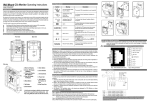
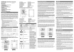
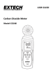
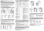
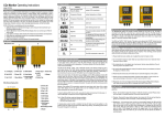
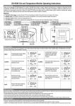
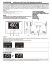
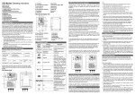
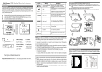
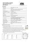
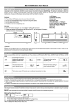
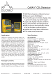
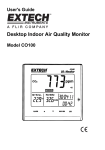
Wall Mount CO2 Monitor Model: ZGw08VRC Operating Instructions As of 20.Aug.2011 【Operation Instruction】 Front view Back view Side view Thank you for selecting ZGw08VRC CO2 wall mount monitor. J Your safety is very important to us .To ensure you use your product correctly and safety, we would like to your attention to read those warning and the entire User Manual before using the product. ☞ Note: *If you do not used this product for a long time, please remove AC adapter and keep them. *We do not guarantee measurement result by this product and/or the result by using the measurement. *This product and measurement result are not for business proof. K 【Product Overview】 This product was developed to detect the presence of CO2 in the ambient air and help people to take care of the Indoor Air Quality. The compact device is designed for use in HAVC in the building. The demand controlled ventilation in the building, also the greenhouse with the CO2 concentration control. By using the CO2 monitor as the indicator, it can easily get the current CO2 concentration together with the ventilation rate. And then adjust the ventilation to the comfort condition automatically by the setting data. So the over-ventilation of the building can be reduced, and the energy can be saved. The ZGw08VRC can be widely used in the office building, green house, school, exhibition, shopping mall. The ZGw08VRC is easy to use and has many features: NDIR ( Non-Dispersive-Infrared) technology used to measure CO2 concentration Three different LED display show the current Indoor Air Quality situation. Voltage (0~5V), Current loop and relay output. Reliable Sensor provides long-term calibration stability. The visual and audible alarm function can be adjustable by user. 【Caring for product】 To make sure you receive the maximum benefit from using this product, please observe the follow guideline. 1. Cleaning ----Disconnect the power before clean. Use a damp cloth, do not use the liquid cleaning agent, such as benzene, thinner or aerosols. 2. Repair---- Do not attempt to repair the product or modify the circuitry by yourself. Please contact with the local dealer or a qualified repairman if the product needs servicing. 3. Calibration--- Please observe the calibration operation to make sure the accuracy for the devices when it‟s necessary. 4. Air circulation---The vents allow the air circulation liquid for measurement of the CO2 concentration and the ventilation should not be blocked. 【Safety Instruction】 L M A. Main LCD Display I. Screw Position B. Green LED Display ( <800ppm) J. Power Terminal 9VDC + C. Yellow LED Display (800-1200ppm) J. Power Terminal 9VDC - D. Red LED Display (>1200ppm) Relay Terminal Block E. Mode Button K. Power Socket F. Up Button L. RJ 45 Cover G. Down Button M. Gas Entry Hole H. Enter Button RJ45 Socket including the RS232 and analog output. Dimension 1. Please take the devices lightly, do not subject the product to impact or shock. 2. Do not immerse the product in water. 3. Please pay attention to the terminal block connection instruction, the wrong mode of operation or opposite installation will destroy the circuit of the devices. 4. Do not touch the exposed electronic circuitry of the device under any circumstances. Keep the circuit is close during installation. As there is the danger of electric shock. 5. Please keep the devices away from children touch to avoid the dangerous or the accident. 6. Do not keep the product under the hot and moisture environment. Keep the product away from the heat source or near water. 7. Please ensure the screws are fixed on the wall tightly. Do not let the screws approach or close to the surface of PCB board during installation. It has the risk of circuit damage or irreparable damage to device. -1- -2- 【LCD Display Symbol】 Symbol CALI 【Installation Step】 Meaning Description CO2 Concentration PPM Parts Per Million The current CO2 concentration in your household. Ventilation Rate L/P/S Liter/Person/Second The Current Liter/ Second Ventilation Rate for one person. Alarm The Alarm Setting Icon, the factory setting with alarm is buzzer off Calibration To calibration the CO2 sensor when the accuracy deviates from the actual CO2 concentration. Alarm Level 1 The Level. Relay status will invert after CO2 level exceeds AL1 The Buzzer and Yellow LED will work after CO2 level exceeds AL1 Alarm Level 2 The 2nd Alarm Level The Buzzer and Red LED will work after CO2 level exceeds AL2 Recover Factory Setting To Recover Factory Setting to cancel the customize Setting Altitude The height above sea level , to compensate the pressure changes Step 1: Release the screw from the device, take the front cover off. Step 2: Release the four screws from the back cover, take the CO2 board from the back cover. Step 3: Connect the power line of AC/DC converter with the 110VAC or 220VAC power line from the power box. Notice: To avoid the danger, please power off the 110VAC/220VAC before connecting. And the power direction must be notice. Step 4: Using the screw to fix the back cover to the current outlet, let the wires come out of the hole. Step 5: Re-assembling the CO2 board by screw to the back cover. Step 6: Connect the power line of AC/DC converter with the power terminal Step 7: After finishing the terminal block wire connection. Press the front cover to the LCD display. Step1 Step2 Step3 1st Alarm 9VDC+ 9VDC- Vent ira t ion on Value well-ventilated 10 poorly ventilated 5 5.6 8.3 8.2 16.4 lps lps lps lps lps lps C O2 m o n e x p r e s s i o n i n J a p a n Japanese Standard Value 36 m3/h/p 18 m3/h/p 20 m3/h/p Building Standards Act 30 m3/h/p standard design 1000 ppm Building Standards Act Lower limit standard design 700 ppm M o n i tCoo rm Step4 Step5 Step6 CO2 Monitor AC/DC Converter Step7 -3- -4- Setting the Altitude mode: 【RJ45 Interface & Wiring Connection】 Fig1: RJ45 Interface (Side View) Fig 2: Wiring Connection 【Customizing Settings】 When the power has been connected, The ZGw08VRC CO2 monitor will begin to work. In order to meet you personal requirement, it is advisable to set up the customizing parameter. Warm Up: It lasts approximately 1min before WARM UP disappears; all MODE functions will not response during warm up. ■Mode setting When pressing MODE button, each mode flashes in the following order: MODE ⇨ MUTE ⇨ ALTI ⇨ ALARM 1 ⇨ ALARM 2 ⇨ OUTSIDE ⇨ CALI ⇨ DATALOGGER ⇨ MAX MIN ⇨ RcFS Then press ENTER to select mode to change. Use UP /DOWN button to change settings and press ENTER to save the data. PRESS PRESS MODE BUTTON ENTER BUTTON 1. Press the MODE, the AL icon flashes. 2. Press the ENTER, AL show on the display. 3. Adjust the display to the actual geographical altitude by up/down button. 4. Press the ENTER again to save the data. Setting the Calibration mode: Ventilation Rate: 1. Press the MODE, the CALI icon flashes. 2. Press the ENTER, CALI show on the display. 3. Adjust the display to the ambient CO2 value by up/down button. 1. Press the up/down to choose the ventilation rate modes. 2. When pressing up button, the LCD display sequence is Vent Rate l/p/s → VentRate cfm/p. When pressing down button, the LCD display sequence is reverse. 4. Press the MODE more than 10 sec, CALI flashes. 5. Calibration will be done automatically after 10minutes and LCD will display „Pass” or “Fail”. If it shows “fails”, please try again. Setting the Alarm parameter Mode: Setting the Alarm function: 1. Press the MODE, the speaker icon flashes simultaneously. 2. Press ENTER, use up/down to select the on/off. 3. Press ENTER again to save the setting. Note: User can set the alarm on/off according to alarm function instruction. -5- 1. Press the MODE, the speaker icon flashes simultaneously. 2. Press ENTER. Using the Up/Down to set the parameter. 3. Press the ENTER again to save the data. Remark: There have AL1 & AL2 when you press the mode. You can set the two different levels on your opinion. The step is 100 ppm per times -6- Using the ReFactSet Mode: 【Calibration】 1. Press MODE, The ReFactSet flashes simultaneously. 2. Press ENTER, Using the Up/Down to select the No/Yes. 3. After the selecting, Press the ENTER to save the changes. Remark: If the user setting the data or calibrate the sensor wrongly. You can use the ReFactSet ( Recover the factory Setting) to come back the factory setting data. 【Specification】 Method - NDIR Sample Method -Diffusion or flow through (50 ~200 ml/min) Notice: Before calibrating, you need standard gas or semi-standard gas, there are 3 methods to get standard gas. ■ Method A: use CO2 in office/building -Use two Meters (One is the device for calibration. The other one is a calibrated (new) one. -Use ambient room gas for calibration in office, waiting at least 10min, until the CO2 reading doesn‟t change. (Notice: user must not breathe toward the ZGw08VRC, CO2 from the user will affect the reading of ZGw08VRC) -Use the reading of the new device as the standard -Calibrate the device by the Cali Mode instruction. ■ Method B: use CO2 outsides -Use ambient room gas for calibration outsides, waiting at least 10min, until the CO2 reading doesn‟t change. (Notice: user must not breathe toward the ZGw08VRC, CO2 from the user will affect the reading of ZGw08VRC) -Use 380~420ppm as the standard reading. -Calibrate the device by the Cali Mode instruction. ■ Method C: use standard CO2 in the bottle -Pump the standard CO2 gas (0~1000ppm, flux = 0.1~0.2 liter/min) into the ZGw08VRC from the Gas Entry Hole waiting about 2~3min. -Calibrate the device by the Cali Mode instruction. ■Performance - CO2 Measurement Range Display Resolution 1ppm at 0-1,000ppm;10ppm at 1,001-3,000ppm Accuracy ±75ppm or ±5% of reading whichever is greater Repeatability ±20 ppm @400ppm Temperature Dependence ±0.1% of reading per °C or ±2 ppm per °C, whichever is greater, referenced to 25°C Pressure Dependence 0.13% of reading per mm Hg Response Time <2min for 90% of step change Warm-Up Time <60 seconds at 22°C Sound Alarm Zone LED Display Power Supply Green:<800ppm Yellow:800~1200ppm Red: >1200ppm (The Factory Setting) (User can adjust) Power Terminal 9VDC (Power Socket 6VDC) 0~5VDC Linear Current Loop Output 40 ~20mA (Max Load is 200 Ohm) Operating Temperature Operating Humidity Range Storage Temperature Ref.No.:042009 70db@10cm Linear Voltage Output Relay Output -7- 0-3,000 ppm display 30VDC or 250VAC, max 2A., SPST. Normal Open 0°C ~50°C(32°F~122°F) 0~95% RH non-condensing -20°C to +60 °C (-4°F to 140 °F) -8-