Download iANT101 Manual
Transcript
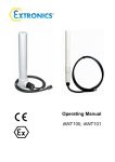
Operating Manual
iANT100, iANT101
Operating Manual
This page is intentionally left blank.
Document Number 314666 (See Last Page for Revision Details)
©2011 Extronics Limited. This document is Copyright Extronics limited.
Extronics reserve the right to change this manual and its contents without notice, the latest
version applies.
2
Operating Manual
Contents
1
2
3
4
5
6
7
8
Introduction.......................................................................................................... 4
1.1
Antenna Profile............................................................................................. 4
Safety Information and Notes .............................................................................. 5
2.1
Storage of this Manual ................................................................................. 5
2.2
List of Notes ................................................................................................. 5
General information ............................................................................................. 7
3.1
Installation and Function .............................................................................. 7
3.1.1
Parts Enclosed ...................................................................................... 7
3.1.2
Antenna Installation Recommendations................................................ 7
3.2
Optional Accessories.................................................................................... 8
3.2.1
iANTMB01............................................................................................. 8
3.2.2
iANTMB02............................................................................................. 9
3.2.3
iANTMB03............................................................................................. 9
Technical Specification...................................................................................... 10
4.1
iANT100 and iANT101 Plots ...................................................................... 10
4.2
iANT100 Specifications .............................................................................. 11
4.3
iANT101 Specifications .............................................................................. 12
4.4
iANT101 Cable Loss .................................................................................. 12
Intended Purpose Usage................................................................................... 13
5.1
Transportation and Storage........................................................................ 13
5.2
Cleaning and Maintenance......................................................................... 13
Fitting of Exd Antenna Cable Gland on iANT100 .............................................. 14
ATEX & IECEx CERTIFICATION ...................................................................... 18
Manual Revision ................................................................................................ 25
3
Operating Manual
1 Introduction
1.1 Antenna Profile
The iANT100 and iANT101 are increased safety antennas and have been
designed and approved by ATEX and IECEx for use in Zone 1 / 21 & Zone 2/22
Hazardous Area Environments.
The iANT100 and iANT101 are optimised for use in WLAN installations in the 2.4GHz
and 5 GHz spectrums for IEEE802.11 a/b/g wireless networks or 2.4GHz and 5GHz
wireless MESH Ethernet networks.
These devices can be used with explosion proof Access Points such as the Extronics
iWAP101 iWAP103 or an Access Point installed in a safe area and just the antenna
installed in the hazardous area.
The units are explosion protected in accordance with IEC 60079-0:2007-10 edition 5,
IEC 60079-31:2008 edition 1, IEC60079-7:2006-07 edition 4, EN 60079-0:2009, EN
60079-7:2007.
The device is certified as:
II 2 GD
Ex e IIC T6 Gb (Ta = -40°C to 60°C)
Ex t IIIC T85°C Db IP66 .
It can operate in areas classified as Zone 1, gas and dust with a temperature class of
T6 with a maximum temperature of 60oC
The minimum permissible ambient temperature is -40oC
The maximum permissible ambient temperature is 60oC
4
Operating Manual
2 Safety Information and Notes
2.1 Storage of this Manual
Keep this user manual safe and in the vicinity of the antenna. All persons who have to work
on or with the controller should be advised on where the manual is stored.
2.2 List of Notes
The notes supplied in this chapter provide information on the following.
• Danger / Warning.
o Possible hazard to life or health.
• Caution
o Possible damage to property.
• Important
o Possible damage to the device, or associated equipment.
• Information
o
Notes on the optimum use of the device
Warning!
The iANT100/iANT101 enclosure is an electrostatic charging hazard;
clean only with a damp cloth
Important
The iANT100/iANT101 may be used in zones 1 and 2 with flammable
gases and vapours with apparatus groups IIA, IIB & IIC and with all
temperature classes.
Important
The iANT100/iANT101 may also be used in zones 21 and 22 with all
flammable dusts compatible with the maximum surface temperature of
60°°C. The appropriate safety margin should be applied
Important
The iANT100/iANT101 is only certified for use in ambient temperatures in
the range -40oC to +60oC and should not be used outside this range
Important
The equipment has not been assessed as a safety-related device (as
referred to by Directive 94/9/EC Annex II, clause 1.5
Important
Installation of this equipment shall be carried out by suitably trained
personnel in accordance with the applicable code of practice (EN 6007914).
Important
If terminated in the hazardous area, the flying lead shall be installed in an
appropriately-certified enclosure. An example would be termination
inside a flameproof enclosure via a suitable certified flameproof gland.
5
Operating Manual
Important
The iANT100/iANT101 and associated wiring should be periodically
inspected for damage, in accordance with the applicable code of practice
(EN 60079-17)
Important
Repair of the iANT shall only be carried out by the manufacturer:
The antenna contains no user-serviceable parts
Warning
The maximum radiated power shall not exceed 2 W
6
Operating Manual
3 General information
3.1 Installation and Function
3.1.1
Parts Enclosed
iANT100
•
•
•
•
•
•
•
•
1 x Antenna with 1mtr / 5mtr cable
1 x M6 x 10 slotted machine screw
1 x M6 lock washer
1 x Antenna Bracket
2 x 1 ¼” x 8 Wood Screws
2 x 6mm red rawl plugs
2 x self adhesive nylon blocks
2 x cable ties
iANT101
•
•
1 x Antenna with Cable as Ordered
1 x Antenna Pipe Mounting Bracket
If any Part is damaged or missing, contact Extronics Ltd
Warning
3.1.2
Ensure that the M6 screw used to affix the iANT100 antenna does not
protrude more than 10mm into the antenna through the attachment
bracket. Protrusion greater than 10mm will cause damage to the
antenna.
Antenna Installation Recommendations
It is recommended that the antennas be mounted at least 204mm (8") away from any
metal objects e.g. metal clad walls or girders.
The antennas should be mounted at least 600mm (24") apart for optimal
performance, but will perform well closer together.
Information
The iANT100 has optional brackets which allow the antenna to be
mounted directly to Extronics Range of hazardous area access points
Information
The iANT101 is supplied with a pipe mounting bracket
7
Operating Manual
3.2 Optional Accessories
3.2.1
iANTMB01
316L Stainless steel wall mount bracket assembly for iANT101
8
Operating Manual
3.2.2
iANTMB02
316L SS Antenna bracket 365mm length for 2 iANT100 / iANT200
antennas for mounting on an iWAP enclosure
3.2.3
iANTMB03
316L Stainless Steel wall mount bracket for iANT100 & iANT200
9
Operating Manual
4 Technical Specification
4.1 iANT100 and iANT101 Plots
2.4GHz
E Plane Pattern Vertical Free Space Beamwidth
Approx 40°°
2.4GHz
H Plane Pattern Vertical Free Space Beamwidth
Approx 40°°
5GHz
E Plane Pattern Vertical Free Space Beamwidth
Approx 40
5GHz
H Plane Pattern Vertical Free Space Beamwidth
Approx 40°°
10
Operating Manual
2.4GH (VSWR) Plot Voltage Standing Wave Ratio <:1
Over 2400—2483 MHz
4.2
5GHz(VSWR) Plot Voltage Standing Wave Ratio
<:1 Over 5000—6000 MHz
iANT100 Specifications
Parameter
iANT100-24
iANT100-58
Power
Max power 1 Watt continuous
Max power 1 Watt continuous
Dimensions
210mm Length, 38mm Diameter
210mm Length, 38mm Diameter
Weight
350g
350g
Connections
Reverse Polarity BNC
(Other connector types available on request)
Reverse Polarity BNC
(Other connector types available on request)
Cable Sealed Lead Length
Supplied as 1 or 5 metre
Suitable for Supplied as 1 or 5 metre
Centre Frequency
2.45 GHz
Suitable for Bands A, B and C
Bandwidth
100MHz
Bands A, B and C
Impedance
50 Ohms
50 Ohms
Return Loss
Better than –12 dB over bandwidth
Better than –12 dB over bandwidth
Gain
5 dBi
8 dBi
Radiation Pattern
Omni Directional
Omni Directional
Radiator Element
Brass tubing, copper plated steel rod
PCB and Brass tubing.
Ambient Temperature
-40°C to 60°C
-40°C to 60°C
IP Rating
IP66
IP66
Certification Number
Sira 11ATEX3100X
IECEx SIR 11.0045X
Sira 11ATEX3100X
IECEx SIR 11.0045X
ATEX Certification
II 2GD Ex e IIC T6 Gb (Ta = -40°C to +60°C)
Ex t IIIC T85°C Db IP66
II 2GD Ex e IIC T6 Gb (Ta = -40°C to +60°C)
Ex t IIIC T85°C Db IP66
IECEx Certification
Ex e IIC T6 Gb (Ta = -40°C to +60°C)
Ex t IIIC T85°C Db IP66
Ex e IIC T6 Gb (Ta = -40°C to +60°C)
Ex t IIIC T85°C Db IP66
11
Operating Manual
4.3 iANT101 Specifications
Parameter
2.4GHz
5.8GHz
Power
Max power 1 Watt continuous
Max power 1 Watt continuous
Dimensions
250mm Length, 38mm Diameter
250mm Length, 38mm Diameter
Weight
480g Not including Cable
480g Not including Cable
Connections
Please Specify with Order
Please Specify with Order
Centre Frequency
2.45 GHz
Suitable for Bands A, B and C
Bandwidth
100MHz
Suitable for Bands A, B and C
Impedance
50 Ohms
50 Ohms
Return Loss
Better than –12 dB over bandwidth
Better than –12 dB over bandwidth
Gain
5 dBi @ 2.4 GHz
8 dBi @ 5.8 GHz
Radiation Pattern
Omni Directional
Omni Directional
Radiator Element
Brass tubing, copper plated steel rod
PCB and Brass Rod
Ambient Temperature
-40°C to 60°C
-40°C to 60°C
IP Rating
IP66
IP66
Certification Number
Sira 11ATEX3100X
IECEx SIR 11.0045X
Sira 11ATEX3100X
IECEx SIR 11.0045X
ATEX Certification
II 2GD Ex e IIC T6 Gb (Ta = -40°C to +60°C)
Ex t IIIC T85°C Db IP66
II 2GD Ex e IIC T6 Gb (Ta = -40°C to +60°C)
Ex t IIIC T85°C Db IP66
IECEx Certification
Ex e IIC T6 Gb (Ta = -40°C to +60°C)
Ex t IIIC T85°C Db IP66
Ex e IIC T6 Gb (Ta = -40°C to +60°C)
Ex t IIIC T85°C Db IP66
4.4 iANT101 Cable Loss
As cable length increases the loss in dB increases
Loss
Loss
Loss
Loss
Loss
Loss
Loss
Loss
Loss
Loss
Loss
Loss
with
with
with
with
with
with
with
with
with
with
with
with
1M lead @ 2.4 GHz
2M lead @ 2.4 GHz
5M lead @ 2.4 GHz
10M lead @ 2.4 GHz
15M lead @ 2.4 GHz
20M lead @ 2.4 GHz
1M lead @ 5.8 GHz
2M lead @ 5.8 GHz
5M lead @ 5.8 GHz
10M lead @ 5.8 GHz
15M lead @ 5.8 GHz
20M lead @ 8.8 GHz
0.22
0.44
1.10
2.20
3.30
4.40
0.36
0.72
1.80
3.60
5.40
7.20
12
dB
dB
dB
dB
dB
dB
dB
dB
dB
dB
dB
dB
Operating Manual
5 Intended Purpose Usage
5.1 Transportation and Storage
All iANT devices must be so transported and stored that they are not subjected to
any excessive mechanical stresses.
5.2 Cleaning and Maintenance
The iANT and all its components require no maintenance and are self-monitoring. All
work on the iANT100 or iANT101 by personnel who are not expressly qualified for
such activities will cause the Ex approval and the guarantee to become void.
Warning!
The iANT100 and iANT101 enclosures are an electrostatic charging
hazard; clean only with a damp cloth
13
Operating Manual
6 Fitting of Exd Antenna Cable Gland on
iANT100
These instructions are intended only for when the iANT100 is to be used with the
iWAP range of enclosures For Full installation instruction also refer to Pepper CR-U
assembly Instructions
Figure 1
Figure 2
Figure 3
Figure 4
14
Operating Manual
Figure 5
Figure 6
Figure 7
15
Operating Manual
Figure 8
Figure 9
16
Operating Manual
1. Split gland as Shown in Figure 1
2. Fit Entry Body into the iWAP enclosure. Hand-tighten, then using wrench
tighten a further ½ turn. DO NOT EXCEED MAX TORQUE FOR
ENCLOSURE
3. Slide Rear Assembly (Back Nut, Mid Cap and Union Nut) onto cable.
CABLE PREPARATION
1. Cut around circumference of cable, being careful not to cut into braid.
2. Slide cable sheath to expose 20-25mm of braid as shown in figure 2.
3. Check compound has not passed its "Use By" date..Note Installation at
temperatures below 10°C should be avoided.
4. Trim any hardened pieces from ends of stick. Mix the compound by
rolling, folding and breaking. Ease mixing by cutting large sticks in half.
Fully mixed compound has a uniform yellow colour with no streaks.
5. Support the cable and Rear Assembly, holding them roughly concentric.
Starting at the middle, pack a small amount of compound around the
screen of the cable as shown in figure 3. Pressing and working the
compound into the braid.
6. Pack Compound around the cable to completely fill the Rear Assembly
cup. Build up compound around the outside of the cores, with a slight
taper & to approximately 40mm in length, as shown in figure 4
7. Pass the cable through and push compound into Entry Body until Rear
Assembly engages. Remove squeezed out compound as Screw Union
full turns onto Entry Body. Ensure that compound emerges at entry
thread, as per figures 7 and 8.
8. Clean off excess compound from Entry Body to allow withdrawal when
cured, as shown in figure 9.
9. Leave to cure for a minimum of 4 hours when working at 21ºC
10. To release and pull back joint for inspection, unscrew Union Nut
11. Hand-tighten Union Nut to remake joint. Then refer to table below and
tighten Union Nut using wrench to the given amount. Hold Mid Cap with
wrench and tighten Back Nut onto cable. Ensure seal makes full contact
with cable sheath, then tighten 1 extra turn
12. The equipment should not be energised until the compound has been
left to cure for at least 4 hours when working at 21ºC. See chart
‘Energising Time vs. Temperature’ for further guidance
HEALTH AND SAFETY WARNING
The resin used in the compound can cause eye and skin irritation. For your personal
protection, wear the gloves supplied while mixing and applying. The uncured
compound should not be allowed to come into contact with foodstuffs.
A COMPREHENSIVE SAFETY DATA SHEET PROVIDED BY THE COMPOUND
MANUFACTURER IS AVAILABLE ON REQUEST
17
Operating Manual
7 ATEX & IECEx CERTIFICATION
18
Operating Manual
19
Operating Manual
20
Operating Manual
21
Operating Manual
22
Operating Manual
23
Operating Manual
24
Operating Manual
8 Manual Revision
Revision
1
2
3
4
5
Description
Original Copy
Added Gland Details
Added iANT101 Version
Added Mounting Bracket Section
New ATEX & IECEx Certificates
Date
24/08/2006
25/05/07
22/08/08
10/12/08
03/05/2011
By
David Revell
Nick Saunders
Nick Saunders
James Eastwood
Nick Saunders
Nick
Saunders
25
Digitally signed by Nick Saunders
DN: CN = Nick Saunders, C = US,
O = Extronics, OU = Extronics
Reason: I am approving this
document
Date: 2011.07.04 22:04:14 +01'00'


