1
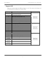
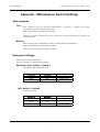
User’s Manual
© Nippon Telesoft Co., Ltd. March 2003.
Appendix : Maintenance Switch Settings
Slide switches
Test
This setting is for use during maintenance to produce a printer test page
containing a mixture of ink characters.
The user should not change this setting.
When set to ON, it enables the user to print a test page containing a mixture of
ink characters.
Memory
This setting is for performing a memory check during maintenance.
The user should not change this setting.
When set to ON, memory checks are done.
Equipment Settings
This switch is for maintenance.
The user should not change this setting.
Equipment Type: Switch 1, Switch 2
Configures the equipment type:
Switch 1
Down
Down
Up
Switch 2
Down
Up
Down
Gemini-Basic
Gemini-Pro
Gemini
LOG: Switch 3, Switch4
Produces a LOG
Switch 3
Down
Switch 4
Down
Down
Up
Up
Down
1
No LOG
Print in Ink On
Reverse Side
Memory
User’s Manual
© Nippon Telesoft Co., Ltd. March 2003.
Segment LED
Whenever an alarm sounds, the LED also displays a value. The contents of the display and
the associated error condition are as shown below.
LED Display
Primary Error Cause
Hardware Errors
0
Communications Settings Switch Communications Speed
1
Communications Settings Switch – Parity
2
Mode Setting Switch memory read
3
Braille Code Setting Switch memory read
4
Paper feed
5
Paper feed reverse rotation
6
Memory check
7
Ink head connection check
8
Servomotor starting point timeout check
Communications Errors
9
RS-232C parity
A
RS-232C overrun
b
RS-232C framing
c
RS-232C central receiver timeout
d
RS-232C buffer overrun
E
Ink character transmission timeout
F
Ink character retransmission overrun
H
Ink character transmission timeout
J
Ink character retransmission overrun
L
Data Receiving Errors
o
Invalid control code
P
Printer setting data
U
Invalid data runaway halted
Prior format missing line feed
 ̄ (upper
segment)
Software Errors
― (middle
Timeout
segment)
Insufficient memory
_(bottom
segment)
(Upper Right
Only segment)
2
Alarm Sound
3 short beeps
followed by
3 short beeps
2 short beeps
followed by
2 short beeps
4 short beeps
followed by
4 short beeps
User’s Manual
© Nippon Telesoft Co., Ltd. March 2003.
LED Handling Procedures
LED Value
Procedure
4
5
9, A, b, c
o, P, U
Load the paper and press the Load Paper switch.
Turn the power off and after ejecting all of the paper, reload the paper.
Please check the PC’s RS-232C communications settings.
Please check the output printer name and output settings of the software
you are using.
Please attempt to correct by rebooting the system.
Other values
3