1
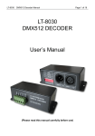
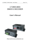
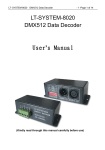
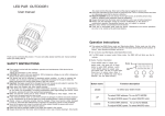
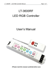
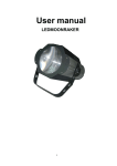
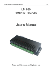
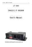
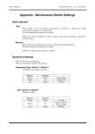
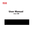
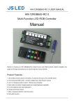
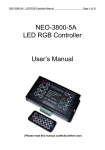
DMX512 Constant Voltage Decoder
User’s Manual
¾ Brief Introduction
Decoder is designed via advanced microchip technology to convert the universal standard DMX512/1990 signal into
most advanced PWM (pulse-width-modulation) digital driving signal, it allows user to choose 1~3 output channel,
256-level brightness control, max 512 output channels. This compact decoder connects to light console, analog device
and various Led terminal products such as RGB Led lamps, RGB Led tubes, building lamps, LED wall washers or
lighting and other compatible devices allowing its user to create endless possibilities of light shows.
¾
¾ Specifications
Model
Input voltage
Max load current
Output Power
Output Scale level
Input signal
Output signal
Output DMX Channel
DMX512 socket
Dimension
Package Size
Weight (G.W)
CONSTANT VOLTAGE 5A
DC12V~DC24V
5A/CH×3
180W/360W(12V/24V)
256 levels
DMX512/1990
3 constant voltage PWM
3Chs or 4Chs (4th CH is shutter strobe)
Standard XLR-3R
L125×W52×H40mm
L135×W70×H50mm
300g
¾
¾ Basic Features
1.
2.
3.
4.
5.
Input standard DMX512 protocol,Address can be set by DIP.
Automatically adapt input voltage DC12V-24V.
3 output channels, 256 scale each, RGB driving control.
10 modes of self-Changing, 8 level of speed changing。
Max output 5A each channel.
Two different versions
3 DMX ADD Version:
The 1st address controls LEDs on CH1,0-255 steps of brightness.
The 2nd address controls LEDs on CH2,0-255 steps of brightness.
The 3rd address controls LEDs on CH3,0-255 steps of brightness.
4 DMX ADD Version:
The 1st address controls LEDs on CH1, 0-255 steps of brightness.
The 2nd address controls LEDs on CH2, 0-255 steps of brightness.
The 3rd address controls LEDs on CH3, 0-255 steps of brightness.
0-127 of the 4th address controls the brightness, 128-255 for strobing
¾ Safety warnings
Please don’t install this controller in lightening, intense magnetic and high-voltage fields.
1. To reduce the risk of component damage and fire caused by short circuit, make sure correct connection
2. Always be sure to mount this unit in an area that will allow proper ventilation to ensure a fitting temperature.
3. Check if the voltage and power adapter suit the controller
(please select DC12-24V power supply with constant voltage)
4. Don’t connect cables with power on; make sure a correct connection and no short circuit checked with instrument before power
on.
5. Please don’t open controller cover and operate if problems occur.
The manual is only suitable for this model; any update is subject to change without prior notice.
¾
¾ 1. Interfaces
DMX Port
Output Port
¾ 2. Conjunction Diagram
1. Connect to LED strip:
2. Connect to DMX system:
-2-
NOTE: According to DMX512 protocol, in order to ensure a steady data transmission, you should add a
metalster(Metal Thin Film resistor,90-120Ω 1/4 W )at the end of each layout of DMX data cable(between Foot 2
and Foot 3, Data + and Data -), please also refer to your DMX console manual to select a correct resistor.
Operating instructions
1. Decoder address setting
This decoder occupies 3 addresses, adopted Dip switch to set the address, the Dip switches from 1 to 9 are a
kind of binary value coding switches used to set DMX512 initial address code, the correlative bits is the 1-9 bits of
the DIP switch, the 1st bit is LSC, the 9th bit MSC , 512 addresses totally.
DMX512 initial address code is equal to the total amount of the Dip switches’ number from 1 to 9, press Dip
switch downward (ON: at position “1”), user can get the number of its position, if pressing upward (at position “0”),
the number of its position is 0.
Accept DMX512 signal only when the DIP switch FUN=OFF (at position “0”)
Example 1: Set to 37
Set the 6th, 3rd, 1st bit of the DIP switch downward to “1”, others to “0” (picture 1), the total sum from 1 to 9 is
32+4+1, so the DMX512 initial address code is 37.
Picture 1
Example 2:
Set DMX512 original address code as 328: Set the 9th, 7rd, 4st bit of the DIP switch downward to “1”, the rest to “0”
(as picture 2), the total sum from 1 to 9 is 256+64+8, so the DMX512 original address code is 328.
Picture 2
Ⅵ. Instructions for other functions
1.Testing function:
The 10th DIP switch is FUN, acting as the function key.
DMX512 Decoder works when FUN is at OFF, receiving DMX512 signals.
Decoder testing mode works when FUN is at position” ON” as Picture 3:
SWITCH1-9 OFF:BLACK
SWITCH1 IS ON:RED
SWITCH2 IS ON: GREEN
SWITCH3 IS ON: BLUE
SWITCH4 IS ON: YELLOW
SWITCH5 IS ON: PURPLE
SWITCH6 IS ON: CYAN
SWITCH7 IS ON: WHITE
Picture 3
SWITCH8 IS ON: 7 CLOLOR JUMPING (8 SPEED LEVELS)
SWITCH9 IS ON: 7 COLOR SMOOTH (8 SPEED LEVELS)
2.Color jumping & color smooth speed
When decoder is at testing mode, DIP Switch 8 is at “ON”, it’s the 7 Color Jumping, when DIP Switch 9 is at
“ON”, it’s the 7 Color Smooth, with 8 speed levels for each effect.
SWITCH 1-7 OFF:SPEED 0
SWITCH 1=ON:SPEED 1
SWITCH 2=ON:SPEED 2
SEITCH 3=ON:SPEED 3
SWITCH 4=ON:SPEED 4
SWITCH 5=ON:SPEED 5
SWITCH 6=ON:SPEED 6
SEITICH7=ON:SPEED 7;
Picture 4
As Picture 4. When several DIP SWITCH at “ON” at the same time, comply with the largest value switch; In
Picture4, it shows the decoder status is color smooth at testing function, and is at Speed 7.
-4-
¾ Exception Handles
Malfunction
No light
Incorrect color
No changes for
certain mode
Output current
less than
350mA/700mA
Cannot Remote
Causation
1. No power from plug
2. Power supply protection
works
3. Incorrect connection or
cable loose
4. Incorrect RGB output wire
connection
4. Re-connect RGB wires
correspondently
5. Speed is too slow
5. Press Speed to accelerate
6. The LEDs at each
channel are not in series
7. the LED quantity in series
is beyond the capacity
8. the input voltage is lower
than the total voltage of
all the LEDS in series.
1. Remote battery is low.
2. Over remote distance
Solution
1. Check the socket
2. Check the malfunction,
re-power on
3. Check connection
6. Connect LEDS in series
7. reduce the LED quantity
8. replace a suitable power
supply
1. Replace a new battery
2. Reduce remote distance
¾ After-Sales
From the day you purchase our products within 2 years, if being used properly in accordance with the instruction, and quality
problems occur, we provide free repair or replacement services except the following cases:
1. Any defects caused by wrong operations.
2. Any damages caused by inappropriate power supply or abnormal voltage.
3. Any damages caused by unauthorized removal, maintenance, modifying circuit, incorrect connections and replacing chips.
4. Any damages due to transportation, breaking, flooded water after the purchase.
5. Any damages caused by earthquake, fire, flood, lightning strike etc. force majeure of natural disasters.
6. Any damages caused by negligence, inappropriate storing at high temperature and humidity environment or near harmful
chemicals.
7. Product has been updated.
¾ Kindly Reminder
Power Source Selection
Power source must be DC constant voltage type of power supply. Due to the efficient output in some power supplies are only 80% of
total, so please select at least 20% higher output power supply than the consumption of LED lights.