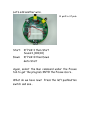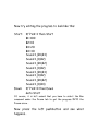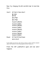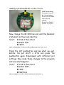
1
physical pins on the IC package and 6 logical
input/output pins (numbered 0 through 5). Logical
I/O pin 5 is dedicated to the Serial Input function
of the downloading process, leaving logical pins 0
through 4 available to use in your design.
Furthermore, logical pin 0 is also shared with the
downloading process so you have to be careful
using this pin. Notice that it is configured as an
output only in the software. Since it toggles, A
LOT, during downloading, don’t attach ‘touchy’
devices to this pin. LEDs, including the dedicated
infrared led function, are a good item for this pin.
END SIDEBAR
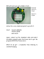
So if you were to build the above circuit and make
the following changes to the program:
Di:
High 2
Sound 1,(B1,B2)
Low 2
Sound 1,(0,B2)
Return
Da:
High 2
Sound 1,(B1,B3)
Low 2
Sound 1,(0,B2)
Return