1
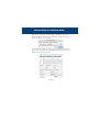
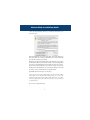
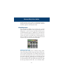
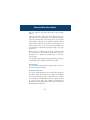
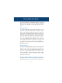
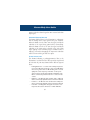
ChannelStrip User Guide
ChannelStrip version 2.0
January 12, 2004
Metric Halo
5 Donovan Drive
Hopewell Junction, NY 12533
tel (845) 223-6112 • fax (603) 250-2451 • Toll Free (888) 638-4527
http://www.mhlabs.com • email: [email protected]
Copyright © 1999-2004, Metric Halo Distribution, Inc.
ChannelStrip User Guide
Quick Installation Guide . . . . . . . . . . . . . . . . . . . . . . . . . . . . . 1
Congratulations . . . . . . . . . . . . . . . . . . . . . . . . . . . . . . . . . . . . 5
What is ChannelStrip. . . . . . . . . . . . . . . . . . . . . . . . . . . . . . . . 5
Operating the Strip . . . . . . . . . . . . . . . . . . . . . . . . . . . . . . . . . 7
Control Knob . . . . . . . . . . . . . . . . . . . . . . . . . . . . . . . . . . 7
Toggle Button . . . . . . . . . . . . . . . . . . . . . . . . . . . . . . . . . . 7
Fader . . . . . . . . . . . . . . . . . . . . . . . . . . . . . . . . . . . . . . . . . 8
Filter type . . . . . . . . . . . . . . . . . . . . . . . . . . . . . . . . . . . . . 8
Sidechain Routing Switch . . . . . . . . . . . . . . . . . . . . . . . . . 8
Compressor character . . . . . . . . . . . . . . . . . . . . . . . . . . . 9
Graphs disclosure control . . . . . . . . . . . . . . . . . . . . . . . . 9
Peak Meter . . . . . . . . . . . . . . . . . . . . . . . . . . . . . . . . . . . . 9
Gain reduction meter. . . . . . . . . . . . . . . . . . . . . . . . . . . 10
Peak, RMS, VU output meter . . . . . . . . . . . . . . . . . . . . . 10
EQ Transfer Function. . . . . . . . . . . . . . . . . . . . . . . . . . . 11
Dynamics Knee . . . . . . . . . . . . . . . . . . . . . . . . . . . . . . . 12
Global Controls . . . . . . . . . . . . . . . . . . . . . . . . . . . . . . . . . . . 13
Working with Pro Tools™ . . . . . . . . . . . . . . . . . . . . . . . . . . 14
Plug-in Window . . . . . . . . . . . . . . . . . . . . . . . . . . . . . . . .15
Key Commands . . . . . . . . . . . . . . . . . . . . . . . . . . . . . . . .17
The Processing – A Detailed Description. . . . . . . . . . . . . . . 17
Input Conditioning . . . . . . . . . . . . . . . . . . . . . . . . . . . . . . . . . 18
Gate/Expander . . . . . . . . . . . . . . . . . . . . . . . . . . . . . . . . . . . . 19
Theory of operation . . . . . . . . . . . . . . . . . . . . . . . . . . . . .19
Gate Enable. . . . . . . . . . . . . . . . . . . . . . . . . . . . . . . . . . . .20
Threshold control. . . . . . . . . . . . . . . . . . . . . . . . . . . . . . .20
Attack control. . . . . . . . . . . . . . . . . . . . . . . . . . . . . . . . . .21
Release control. . . . . . . . . . . . . . . . . . . . . . . . . . . . . . . . .21
ChannelStrip User Guide
Using the Sidechain Key input w/selectable filter . . . . . .21
Sidechain Routing Button . . . . . . . . . . . . . . . . . . . . . . . . .22
Filter type button . . . . . . . . . . . . . . . . . . . . . . . . . . . . . . .22
Filter enable button . . . . . . . . . . . . . . . . . . . . . . . . . . . . .23
Filter band boost/cut control . . . . . . . . . . . . . . . . . . . . . .23
Filter band frequency . . . . . . . . . . . . . . . . . . . . . . . . . . . .23
Filter bandwidth . . . . . . . . . . . . . . . . . . . . . . . . . . . . . . . .24
Compressor . . . . . . . . . . . . . . . . . . . . . . . . . . . . . . . . . . . . . . 24
Theory of Operation . . . . . . . . . . . . . . . . . . . . . . . . . . . .25
Audio Dynamics . . . . . . . . . . . . . . . . . . . . . . . . . . . . . . . .26
Compressor Enable . . . . . . . . . . . . . . . . . . . . . . . . . . . . .27
Post EQ. . . . . . . . . . . . . . . . . . . . . . . . . . . . . . . . . . . . . . .27
Auto Gain . . . . . . . . . . . . . . . . . . . . . . . . . . . . . . . . . . . . .27
Manual make-up gain . . . . . . . . . . . . . . . . . . . . . . . . . . . .28
Compressor Character . . . . . . . . . . . . . . . . . . . . . . . . . .28
Threshold control. . . . . . . . . . . . . . . . . . . . . . . . . . . . . . .29
Ratio Control . . . . . . . . . . . . . . . . . . . . . . . . . . . . . . . . . .29
Attack control. . . . . . . . . . . . . . . . . . . . . . . . . . . . . . . . . .29
Release control. . . . . . . . . . . . . . . . . . . . . . . . . . . . . . . . .30
Using the Sidechain Key input w/selectable filter . . . . . .30
Sidechain Routing Button . . . . . . . . . . . . . . . . . . . . . . . . .30
Filter type button . . . . . . . . . . . . . . . . . . . . . . . . . . . . . . .31
Filter enable button . . . . . . . . . . . . . . . . . . . . . . . . . . . . .32
Filter band boost/cut control . . . . . . . . . . . . . . . . . . . . . .32
Filter band frequency . . . . . . . . . . . . . . . . . . . . . . . . . . . .32
Filter bandwidth . . . . . . . . . . . . . . . . . . . . . . . . . . . . . . . .33
Equalizer . . . . . . . . . . . . . . . . . . . . . . . . . . . . . . . . . . . . . . . . . 33
Theory of operation . . . . . . . . . . . . . . . . . . . . . . . . . . . . .34
ChannelStrip User Guide
Master Enable button . . . . . . . . . . . . . . . . . . . . . . . . . . . .35
Filter type button . . . . . . . . . . . . . . . . . . . . . . . . . . . . . . .35
Filter enable button . . . . . . . . . . . . . . . . . . . . . . . . . . . . .36
Filter band boost/cut control . . . . . . . . . . . . . . . . . . . . . .36
Filter band frequency . . . . . . . . . . . . . . . . . . . . . . . . . . . .37
Filter bandwidth . . . . . . . . . . . . . . . . . . . . . . . . . . . . . . . .37
Controlling the EQ with the Transfer Function . . . . . . .38
EQ output gain . . . . . . . . . . . . . . . . . . . . . . . . . . . . . . . . .38
Delay Section . . . . . . . . . . . . . . . . . . . . . . . . . . . . . . . . . . . . . 38
Conclusion . . . . . . . . . . . . . . . . . . . . . . . . . . . . . . . . . . . . . . . 39
Service and Support . . . . . . . . . . . . . . . . . . . . . . . . . . . . . . . . 39
ChannelStrip Installation Guide
Quick Installation Guide
Installing and registering your Metric Halo software product is a simple 7
step process.
1. Insert the installation media into your computer.
Double-click the “CSTDMInstaller” application on the CD.
After a few seconds an installer dialog will appear:
Enter the serial number that is printed on the serial number sticker which is
found either on the CD sleeve or on the inside cover of your ChannelStrip
manual.
2. Under normal circumstances the installer will automatically locate the
proper destination for your plug-in software. Unless you have a special reason to install your ChannelStrip software in a different location, use the
default location provided by the installer.
If you need to install the software in a custom location, click the “Select
Destination Directory…” button to choose the software installation location. A folder selection dialog box will appear (next page):
1
ChannelStrip Installation Guide
Navigate until you have selected the appropriate folder to contain the software and then click the “Open” button at the bottom of the dialog. The
folder selection dialog box will close
3. Now click the “Install” button in the Installer dialog. Installation will
require about 1 minute.
4. Congratulations! Your software is now installed. The installer has provided a temporary license so that you can get started immediately. You will
need to register the software with Metric Halo within 12 days to get the
authorization code to convert the license to a permanent one.
You can now use your software immediately (even before it is authorized)!
The software will inform you once each time you start Pro Tools that the
license is temporary and will tell you the amount of time that remains on
license before it will expire.
5. In order to permanently authorize your software you will have to obtain
an authorization code from Metric Halo. To permanently authorize your
new ChannelStrip plug-in, use the “Authorizer(CS)” application included in
the same folder as the installer.
2
ChannelStrip Installation Guide
After a few seconds the following dialog box will appear (if you have a
number of hard disks attached to your machine, it may take some time for
the dialog to appear… this is normal):
Click the Authorize button and complete the registration dialog box to personalize your copy of ChannelStrip and generate a challenge code (software
ID) that you will send to Metric Halo.
(continued)
3
ChannelStrip Installation Guide
6. There are three methods by which you can obtain an authorization code
from Metric Halo:
(1) [Preferred] Click the “Send request via the Web” button in the dialog above.
Your request will be processed by our authorization server and your authorization code will be emailed to you instantly.
(2) Click the “Send Request via Email” button in the dialog above. Your registration information will be copied to the clipboard and a new email message will be
created for you automatically. Paste the information into the body of the message and send it to Metric Halo. Please do not edit the contents of the message.
We will send you the authorization code via email. Please allow up to three business days to receive your authorization code using this method.
(3) Call (845) 223-6112 and register over the phone.
7. After you have received your authorization code, type it into the “Authorization Code” box in the authorization dialog. If the code is correct, the
“Authorize” button will become enabled. If the button does not enable,
check your typing. Click on the “Authorize” button to convert your license
to a permanent one.
That’s it! Enjoy using ChannelStrip!
4
ChannelStrip User Guide
Congratulations
Thank you for purchasing ChannelStrip. You have just transformed your Digital Audio Workstation into a world class
mixing console. ChannelStrip provides all of the critical
channel processing features you would expect to find on a
top-of-the-line mixing console in a single mono or stereo
plug-in. ChannelStrip combines stunning sound quality with
a convenient interface designed to allow you to control all
critical channel processes interactively and simultaneously just like you would on a real console!
What is ChannelStrip
ChannelStrip is a plug-in for digital audio workstations
which provides the essential basic channel processing found
in the channel strip of a modern mixing console.
Processing functions include:
• Input level control
• Expander/Gate with filtered sidechain
• Compressor with filtered sidechain
• 6 band Parametric EQ
• Phase Invert
• Channel delay
• Advanced metering
ChannelStrip was designed with three primary goals in mind:
1. To sound mind-numbingly good.
2. To be flexible and easy to use.
3. To be as DSP efficient as possible while maintaining
stunning sound quality.
5
ChannelStrip User Guide
Figure 1: The ChannelStrip Plug-in Window
6
ChannelStrip User Guide
Operating the Strip
As with most channel strips, ChannelStrip provides many
copies of controls that are all operated in a similar manner.
The ChannelStrip user interface uses a few different control
elements to control all of the processing. These elements are:
Control Knob
Control Knobs are used to control the value of various
continuous parameters of a process. Examples of these
types of parameters include: Attack time, Release Time,
Threshold, etc. You can change the value of each knob in a number
of different ways. Click and drag the knob to change the value continuously. Dragging up or to the right will increase the value, while
dragging down or to the left will decrease the value. If you hold
down the <command> key when you click, you will be able to
adjust the value with finer precision. If you hold the <option> key
when you click, the knob will reset to its default value.
Click on the number (readout) of the knob to pop up a text entry
field that allows you to type in a number directly. The popup will
remain active until you dismiss it by clicking somewhere else or hitting the <return>, <enter>, <tab>, or <command>–<period> keys.
Hit <return> or <enter> to confirm the value and dismiss the
popup. Hit the <tab> key to confirm the value and pop up an entry
field for the next control (<command>–<tab> will pop up the entry
field for the previous control). Hit <command>–<period> to dismiss the popup and cancel the change.
When you enter a number into the pop up entry, you can use a
couple of abbreviations: “k” multiplies the number by 1000 and “m”
divides the number by 1000. So if you want to enter 16,500 Hz you
can just type 16.5k.
Toggle Button
Toggle buttons are simple on/off switches. They light up
when they are on and are dark when they are off.You toggle the state of the button by clicking on it. These buttons
7
ChannelStrip User Guide
are used to enable processor sections and to switch the order of
processing within ChannelStrip.
Fader
The fader is somewhat unique in that only one fader is
used in the interface for ChannelStrip. It works in much
the same fashion as the control knobs. Instead of dragging up/right or down/left to change the value, you
directly drag the fader knob. The other “tricks”
described for the knobs also work with the fader. The
fader is used to control the output gain of the EQ section of ChannelStrip. This controls a high-precision 56bit gain stage that maintains the full precision of the 48bit EQ algorithm provided by ChannelStrip.
Filter type
Each filter band in the strip (6 EQ bands and 2 Side-chain bands) has
a filter type control that allows you to choose the shape of the filter
applied by that band. Each band provides 6 different types of filter
shapes: Peaking/Parametric, Low Cut, High Cut, Low Shelf, High
Shelf, and Bandpass. You can select from these types via two different methods. Each time you click on the Filter Type control, the
band will switch to the next type in the list (and wrap to the beginning when you hit the end of the list). If you click and hold the
mouse button, a pop-up menu listing all of the types will appear
after about 1/4 of a second. You can select the type directly from
this popup menu. If you want to access the menu without having to
wait, hold down the <command> key when you click.
Sidechain Routing Switch
Each sidechain routing switch allows you to control the signal sent
to the sidechain input of its associated gate or compressor. By
default, the level detectors in the dynamics processors key off of the
signal that they are processing. Under some circumstance, you may
want to use a different signal to open the gate or compress the signal. Pro Tools allows you to specify an input or bus as the source for
ChannelStrip’s sidechain input. The Sidechain routing switches allow
8
ChannelStrip User Guide
you to choose the input to the level detector from the sidechain
(key) input or the signal being processed. To toggle the state, click
the Sidechain routing switch.
Compressor character
The compressor character controls the time constants of the compressor section. It functions identically to the Filter Type control,
except there are only three choices: Smooth, Warm and Fast. See
the section on the compressor for more information.
Graphs disclosure control
The Graphs disclosure control allows you to show
and hide ChannelStrip’s display graphs. This allows you to maximize
screen real-estate while still providing details on the processing
when they are needed. Click on this control to toggle the visibility
of the graphs. ChannelStrip will automatically make the plug-in window smaller when you hide the graphs.
ChannelStrip also uses a number of standard visual representations to give you feedback about what is happening within
the processor. These elements are:
Peak Meter
ChannelStrip provides a peakreading meter at the input stage
of each processing block. The meter uses the fast PPM standard for
decay time (0.9 seconds per 20 dB) and the digital PPM standard
legend for calibration. On the dynamics sections (gate and compressor) an orange triangle is visible on top of the meter and indicates
the current detector level. For the dynamics sections the processor
threshold is indicated by the green arrow above the input peak
meter. This green arrow can be manipulated directly with the
mouse. The top segment of the meter (above 0dB) is used as a clip
indicator and is illuminated red if the input section of the processor
detects an over. The clip light remains illuminated until you click on
9
ChannelStrip User Guide
the meter. <option>–click any meter to reset the clip lights on all of
the meters in ChannelStrip. When ChannelStrip is running in stereo
mode, this meter shows the higher of the two input levels and will
detect an over on either input channel.
Gain reduction meter
The gain reduction meter, which
has an orange bar and grows down
from 0 dB, shows the amount of attenuation being applied by its
associated dynamics processor at any given time. Please note that
the dynamic range of this meter is 60 dB which is huge as compared
to most gain reduction meters on other processors. We provided
such a large dynamic range because the dynamics processors in
ChannelStrip are capable of providing tremendous amounts of gain
reduction without artifact or distortion. Since the dynamic range is
so large, it is possible to compress a signal fairly aggressively without
seeing much activity on the gain reduction meter. Please refer to the
knee diagram for feedback in this case.
Peak, RMS,VU output meter
For the main output stage of ChannelStrip we have
provided meters driven with SpectraFoo metering
technology. These meters show, in addition to the
peak metering provided for the input stages, RMS
level and VU level. The peak level is represented by
the floating colored bar, the RMS level by the solid
colored bar and the VU level by the overlaid gray
bar. Both the Peak and RMS level are represented
with fast PPM ballistics. The VU meter shows IEEE
standard 300 ms RMS average level. When ChannelStrip is on a mono insert both output meters show the mono channel output. When ChannelStrip is running in stereo mode the left
meter shows the left channel output level and the right meter
shows the right channel output level. The output section clip lights
activate if there is an over in the output stage or in any of the processing section input stages. It is reset by clicking on the meter;
<option>–click to reset the clip lights on all the meters.
10
ChannelStrip User Guide
EQ Transfer Function
The EQ transfer function is a
combination of a visual representation of how the EQ is
processing the signal and an
intuitive controller for the
associated filter bands. This
display is sometimes called a
“Cartesian Graph” by other EQ manufacturers.
The horizontal axis provides frequency calibration in Hertz (Hz).
The vertical axis provides level calibration in decibels (dBr). The
heavy green line indicates the relative change in level at each frequency that is created by the combined effects of all of the active
bands in the equalizer. Each EQ band is represented by a colored
dot in the transfer function. The color of the dot matches the color
of the numeric readouts of the knobs for the corresponding EQ
band.
The band that is currently being edited will have a light gray crosshair centered under it. If the associated band is a parametric filter
there will also be two smaller colored dots that can be used to control the bandwidth of the filter. Clicking on a large colored dot and
dragging will allow you to adjust the frequency and gain of the associated band. <command>–click the dot to toggle the band enable.
<option>–click the dot to adjust the bandwidth (dragging right
increases the bandwidth, left decreases the bandwidth). <command><option>–click the dot to switch the band filter type. Click
and drag the smaller dots associated with a larger dot to adjust the
filter bandwidth.
In order to increase the real-time performance of changing EQ
parameters, the transfer function graph switches to a lower resolution mode while you are changing parameter values. You may find
that the graph “jumps” slightly when you are editing narrow parametric filters.
11
ChannelStrip User Guide
Dynamics Knee
ChannelStrip
contains
a
Dynamics Knee diagram for
each gate and each compressor processing section. The
diagram provides feedback on
the response of the associated dynamics processor.
Both the horizontal and vertical axes are calibrated in
dBFS. The horizontal axis corresponds to the input level
and the vertical axis represents the output level. The heavy line shows the quiescent dynamical
response of the associated processing block. This means that if you
sent in a sine wave at a given input level, the output level would be
equal to the level shown on the graph. When the processor is working with real dynamic signals, the graph is a good approximation of
the response when the attack is fast and the release is slow.
In most cases, however, the dynamic response of the processor will
not match its static response. In order to represent this, we have
included a “bouncing ball” meter for both the gate and the compressor. This metering is shown as a red square that is overlaid on the
knee diagram. The red square is placed so its horizontal position is
equal to the instantaneous input level and its vertical level is equal
to the instantaneous output level. Examining this meter while you
are adjusting the dynamics controls will provide you with a great
deal of information about how the processor is operating and how
the controls interact.
12
ChannelStrip User Guide
Global Controls
ChannelStrip has a few global controls that effect all
instances of the plug-in on every session. You can use these
controls to change the appearance of ChannelStrip to match
your mood and style. These preference controls are accessed
from the ChannelStrip “About Box”. To show the about box,
click on the Metric Halo logo or the ChannelStrip logo on
the control surface. This will bring up a dialog box with
copyright and contact information for Metric Halo. This
about box also names the beta testers who helped Metric
Halo test the product (these people deserve thanks from all
of us – ChannelStrip is a better product due to their efforts).
The block diagram shows the signal flow through the processor (this diagram changes based upon the current ordering of
the processing blocks). Finally, below the block diagram
there are two controls:
•
•
Use Custom Color – Click this to use a custom flat
color for the background plate of ChannelStrip instead of
the standard background texture.
Choose Color… – Click this to choose the custom color
to use.
13
ChannelStrip User Guide
Click anywhere else or type a character to dismiss the about
box. These preferences are global and shared between all
instances of the ChannelStrip.
Working with Pro Tools™
Your Pro Tools software provides a standard interface for
controlling various aspects of TDM plug-ins. While you
should refer to your Pro Tools documentation for a complete
description, we will summarize the most important points
here.
Since you will want to use ChannelStrip on every channel in
your mix, you should <option> insert ChannelStrip on all of
your main mono mix channels and ensure that ChannelStrip
is inserted on the same insert point on every channel (e.g.
ensure that ChannelStrip is on insert a for every channel).
This will allow you to take advantage of a number of time
saving features provided by Pro Tools.
14
ChannelStrip User Guide
PLUG-IN WINDOW
The illustration below shows the standard Pro Tools plug-in
window.
If you have inserted ChannelStrip as we suggested above you
can click on the channel name popup in the upper left hand
corner of the window (labeled “1 KIK.02” above) to switch
from channel to channel.
The next popup in the window (labeled “a” above) allows
you to switch to another insert on the same channel. You
would use this to switch to another plug-in on the same
channel.
The bypass button allows you to bypass the effects of ChannelStrip. When the bypass is turned on all of the processing
sections, including the user-configured delay, of ChannelStrip are bypassed. When the strip is bypassed there is still a
40 sample delay through the processor but all samples pass
through unchanged.
The Pro Tools editor/librarian button (the small downward
pointing triangle) provides access to a popup menu that
allow you to manage presets and libraries of setting for
ChannelStrip. Use this menu to save libraries or open groups
of libraries. See your Pro Tools documentation for more
information.
The preset library popup menu (labeled “factory default”
above) shows the active preset name (in italics if the current
15
ChannelStrip User Guide
settings do not match the library). Click this popup to select
from the available presets.
The “Compare” button indicates when the controls have
changed for the current preset settings. Click this button to
toggle between your current settings and the preset settings.
Clicking the “Automation” button causes Pro Tools to display
the plug-in automation configuration dialog box. This dialog
box allows you to enable any or all of the 61 processing
parameters for automation. When a parameter is enabled for
automation you will be able to record and play-back automated parameter changes directly from your Pro Tools session. If the channel that ChannelStrip is inserted on has
automation enabled ChannelStrip will highlight the controls
associated with the automated parameters.
The sidechain input popup menu allows you to select from
any mono input or bus in your system and feed it to the internal sidechain bus within ChannelStrip. You then use the
sidechain routing buttons to assign the sidechain bus to the
gate and compressor detectors.
16
ChannelStrip User Guide
KEY COMMANDS
Pro Tools provides two standard key commands for use with
plug-in automation. <control><option><command>–click a
control to pop up a menu that allows you to enable/disable
automation of the associated parameter, or to bring up the
automation dialog. <control><command>–click a control to
cause Pro Tools show that control’s automation breakpoint
graph in the Pro Tools edit window.
The Processing – A Detailed Description
In this section we discuss what each processing block does
and how the controls work. ChannelStrip is unique among
TDM plug-ins in that it provides all the basic channel processing that you need in a complete package. It accomplishes this through a combination of elegant user interface
design and incredible DSP coding. ChannelStrip provides all
basic channel processing in the same amount of DSP as one
6–band Focusrite d2 EQ and it sounds better.
Channel
Input
Key Input
SC
Filter
In Gain
Phase
Invert
Level
Detector
Gate
VCA
Out Gain
Key
Input
SC
Filter
Adjustable
255 Sample
Delay
Channel
Output
6 Band
EQ
Comp Pre/Post EQ
Level
Detector
8 Sample
Delay
CompVCA Makeup
Gain
The block diagram above illustrates the overall structure of
17
ChannelStrip User Guide
the processing system provided by ChannelStrip. This diagram does not indicate the various metering blocks. The
ganged switch in the diagram is controlled by the “Post EQ”
button in the compressor and it changes the path of the signal through the processor. The internal signal switching provided by ChannelStrip allows you to explore the various
effects of re-ordering processing blocks without having to
waste time stopping the transport, removing and reinserting
plug-ins and then finally restarting the transport.
Now lets examine the various processing blocks indicated in
the diagram.
Input Conditioning
After the signal is routed to ChannelStrip it runs through an
input gain block that provides input gain of up to +24 dB.
You can use this gain to condition signals that are low in
level.
This input gain may also be used to pad out signals by up to
–24 dB. While you may find this attenuation useful to just
bring down the level through the strip simply and quickly,
you must realize that this gain is applied after the signal
reaches ChannelStrip and will not pad out any clipping that
occurs in the A/D converters or in a plug-in that is inserted
before ChannelStrip.
The input gain is controlled by the “In Gain” knob.
After the input gain/pad section, there is a phase invert
block. This block is controlled by the “ø Inv” switch. When
the phase invert is enabled the polarity of the signal will be
flipped. The signal is cross-faded between the uninverted
18
ChannelStrip User Guide
and inverted states so the signal level will drop briefly when
you flip the state of the phase invert switch, but it will not
introduce a glitch or click into your audio.
Gate/Expander
The next processing block is the Gate. The gate is used to
adjust the low level dynamics of the signal being processed.
Through the use of the external side-chain the gate can be
used to do acoustic triggers. In addition, the side chain filter
may be used to make the control of the dynamics frequency
sensitive. This can be useful when you are trying to gate out a
noisy signal that has a specific, very strong signal in a limited
frequency range when you want the gate to open.
THEORY OF OPERATION
Based upon your setting for the sidechain routing switch,
either the Pro Tools sidechain input signal or the channel signal is fed to the sidechain filter. The sidechain filter provides
one band of equalization that may be used to accentuate or
cut certain frequencies (parametric or shelf filters) or limit
the key to a certain range of frequencies (cut or bandpass filters). You control the filter type and the filter parameters with
the filter type button and the “dB”, “Hz” and “BW” knobs.
19
ChannelStrip User Guide
You can enable the side chain filter with the green enable
button.
After the sidechain signal has been processed by the
sidechain filter it is measured by a level detector that determines the instantaneous level of the signal (in the case that
ChannelStrip is running in stereo mode the detector is linked
with the other channel in the stereo pair and the higher level
of the two channels is used). The measurement made by the
level detector is indicated by the orange triangle in the gate
input meter.
When the gate is enabled using the orange “Enable” button
the signal will be attenuated based on how much the
detected level is below the threshold you set with the
“Thres” knob.
The dynamic behavior of the opening and closing of the gate
is controlled with the “Attack” and “Release” knobs.
GATE ENABLE
The gate enable button enables the gating action. If this button is off, no gating will occur.
THRESHOLD CONTROL
The “Thres” knob controls the level at which the gate opens
and closes. When the detector level is above the threshold
level the gain through the gate is 0 dB. When the detector
level is below the threshold level, the gain reduced at a ratio
of 1:2. This means that if the detector is 3dB below the
threshold the signal output will be 6dB below the threshold
or 3dB below the input level.
20
ChannelStrip User Guide
The gate threshold level is also indicated by the green arrow
above the gate input meter. You can adjust the threshold
level using this indicator as well as by using the “Thres”
knob.
ATTACK CONTROL
The “Attack” knob allows you to adjust how quickly the gain
reduction is decreased to 0 dB when the detector level goes
above the threshold level. When this control is set to Auto,
the attack rate is controlled by how much the detector level
is above the threshold. When you set the attack to another
value other than “Auto” that value, measured in milliseconds, will control how quickly the gate opens. The maximum value is 100 milliseconds. Attack times other than auto
are especially useful when using the gate as a trigger. If the
key signal is a little early you can use the attack to delay the
trigger slightly. It is also useful to remove the initial transients
of impulsive sounds.
RELEASE CONTROL
The “Release” knob controls the release time of the gate. This
parameter is measured in milliseconds and can range from 5
ms to 5 sec. The release time controls how quickly the gate
closes after the detector drops below the threshold value. For
settings below 90 ms or so the gate closes pretty abruptly
and may introduce unwanted artifacts into your audio,
depending on the signal.
USING THE SIDECHAIN KEY INPUT W/SELECTABLE FILTER
The gate provides a sidechain that processes audio before
the detector determines the current level. The sidechain can
21
ChannelStrip User Guide
process either the channel signal or some external side chain
input signal.
SIDECHAIN ROUTING BUTTON
This button (labeled “chan” in the illustration) is used to control the routing of the input signal to the gate sidechain.
When the button is in the “chan” state, the signal used by the
sidechain is the signal being processed by ChannelStrip.
When the button is in the “sc-in” state, the signal used by the
sidechain is the input or bus selected in the “side chain
input” popup in the Pro Tools plug-in window header. If
nothing is selected in that popup, the input to the sidechain
will be silence and the gate will never open.
FILTER TYPE BUTTON
This button (indicating a peaking/parametric filter in the
illustration) is used to select the filter type of the single band
of side chain EQ. You may choose from 6 different types of
filters:
•
•
•
•
Peaking/Parametric – a second order bell-shaped parametric boost/cut filter. Boost/cut has a range of ± 24 dB. When
the boost is greater than +15 dB the filter gains a resonant
quality. The center frequency of the filter can be any frequency between 20 Hz and 20 kHz. The bandwidth of the
filter is continuously variable between 0.1 octaves and 2.5
octaves.
High Cut – a 12 dB/octave high cut filter with a -3dB point
that is continuously adjustable between 20 Hz and 20 kHz.
Low Cut – a 12 dB/octave low cut filter with a -3dB point
that is continuously adjustable between 20 Hz and 20 kHz.
Low Shelf – a shelving filter that applies boost/cut to low
frequencies. Boost/cut is limited to +12 dB/– 24dB. The
22
ChannelStrip User Guide
•
•
bandwidth controls the dip/peak that is added at the end of
the transition band.
High Shelf – a shelving filter that applies boost/cut to high
frequencies. Boost/cut is limited to +12 dB/– 24dB. The
bandwidth controls the dip/peak that is added at the end of
the transition band.
Bandpass – a bandpass filter with 6dB per octave skirt on
the high and low ends of the pass band. The width of the
pass band can be adjusted between 0.1 octaves and 2.5
octaves and the center of the pass band is continuously
adjustable between 20 Hz and 20 kHz.
FILTER ENABLE BUTTON
Use this green toggle button to enable the sidechain filter.
When the filter is turned off the signal will pass through the
sidechain filter unchanged.
FILTER BAND BOOST/CUT CONTROL
Use this knob (labeled “dB” in the illustration) to adjust the
gain of the filter band for the peaking, high and low shelf filter types. This parameter is ignored for the other filter types.
In the shelving filters the maximum boost is +12 dB and the
maximum cut is -24 dB. In the peaking filters the maximum
boost/cut is ± 24 dB. When you increase the boost for a filter
band above 15 dB, the filter gets nicely aggressive and resonant.
FILTER BAND FREQUENCY
Use this knob (labeled “Hz” in the illustration) to adjust the
characteristic frequency of the filter. For the peaking and
bandpass filter types this controls the center frequency of the
filter. For the high and low cut filter types this control adjusts
23
ChannelStrip User Guide
the 3 dB point of the filter. For the shelving filters this control
adjusts the shelf transition point.
FILTER BANDWIDTH
Use this knob (labeled “BW” in the illustration) to adjust the
characteristic width of the filter. This control only has effect
for peaking, shelving and bandpass filter types. Please note
that this parameter controls the bandwidth (measured in
octaves), not the quality factor (or “Q”). If you have been
using Q controls, the numbers will be backwards from what
you are used to. Small numbers mean narrow filters and
large numbers mean wide filters. For peaking and bandpass
filter types, this parameter controls the bandwidth of the filter in octaves. For the high and low shelving filter types this
parameter adjusts the amount of dip/peak and the slope of
the shelf. When this parameter is set to 0.1 you will get the
largest dip/slope available and when the parameter is 2.5,
you will get a classic first order shelf (which has a transition
band that is about 1 decade wide; e.g. if it is a high shelf
with a frequency of 10 kHz and a gain of 10 dB, the gain will
be at 0 dB near 1kHz).
Compressor
Depending on the state of the “Post EQ” button (the default
state is for the compressor to come first in the signal chain),
the next block in the signal processing chain is the compressor. The compressor is used to adjust the high–level dynamics of a signal. As with the gate, the sidechain can be used to
make the compressor frequency sensitive (so it can be used
like a de-esser) or to reduce the gain of the signal in response
24
ChannelStrip User Guide
to some external event (this allows the compressor to be
used like a ducker or for other creative effects).
Often, you will want to compress the signal before you
equalize it. Sometimes you will need to equalize the signal
before you compress it. ChannelStrip provides that flexibility
with the “Post EQ” button. This is a very important part of
ChannelStrip because it allows you to test different processing scenarios quickly and easily. It also allows you to compare the two different approaches without having to stop the
transport so you can get a much more visceral comparison.
THEORY OF OPERATION
The operation of the compressor is very similar to the gate.
Based upon your setting for the sidechain routing switch,
either the Pro Tools sidechain input signal or the channel signal is fed to the sidechain filter. The sidechain filter provides
one band of equalization that may be used to accentuate or
cut certain frequencies (parametric or shelf filters) or limit
the key to a certain range of frequencies (cut or bandpass filters). You control the filter type and the filter parameters with
the filter type button and the “dB”, “Hz” and “BW” knobs.
25
ChannelStrip User Guide
You can enable the sidechain filter with the green enable
button.
After the sidechain signal has been processed by the
sidechain filter it is measured by a level detector that determines the instantaneous level of the signal (in the case that
ChannelStrip is running in stereo mode the detector is linked
with the other channel in the stereo pair and the higher level
of the two channels is used). The measurement made by the
level detector is indicated by the orange triangle in the compressor input meter. The channel signal is delayed by 8 samples relative to the detector signal to allow the compressor to
have an instantaneous attack when the “Attack” parameter is
set to 0.
When the compressor is enabled using the orange “Comp
Enable” button the signal will be attenuated based on how
much the detected level is above the threshold you set with
the “Thres” knob and what compression ratio is set with the
“Ratio” knob.
The dynamic behavior of the opening and closing of the gate
is controlled with the “Attack” and “Release” knobs and the
compressor character switch.
AUDIO DYNAMICS
Compressors are important in controlling the dynamic range
of the source material you are working with. While the
instruments, your ears, the microphones and your digital
audio workstation all have dynamic ranges that are greater
than 100 dB, most reproduction and delivery media have
significantly reduced dynamic ranges. Compression is used,
in its simplest form, to help reduce the dynamic range of
26
ChannelStrip User Guide
your project or elements of the project to a range that is
reproducible. It does this by making the soft material louder
and the loud material softer. This type of processing can also
be used to change the character of the sound instead of just
adjusting the dynamic range. The compressor in ChannelStrip excels at both types of processing.
COMPRESSOR ENABLE
The “Comp Enable” button enables the compressor action. If
this button is off, no compression will occur.
POST EQ
The “Post EQ” button places the compressor section after the
equalizer in the signal chain. By providing the capability to
switch the routing on the fly, ChannelStrip allows you to
determine the most effective routing for your particular signal quickly and easily.
AUTO GAIN
Enabling the “Auto Gain” button causes the compressor to
automatically adjust the makeup gain in the compressor output stage so that if the manual “O Gain” knob is set to 0 dB
the static gain reduction for a 0 dB input level will be about
7 dB. This number was chosen because it works well with
the default settings of the “Attack” and “Release” knobs to
provide enough pad to not clip fast transients. The “O Gain”
knob will apply additional trim to the internal automatic
gain. If the threshold is set very low (e.g. –60 dB) and auto
gain is enabled, you will not be able to add very much manual gain (only about 1 – 2 dB) even though the readout on
27
ChannelStrip User Guide
the knob will go up to + 30 dB. This is an internal limitation
of the compressor.
MANUAL MAKE-UP GAIN
The “O Gain” knob allows you to manually adjust the
makeup gain applied to the signal after the gain reduction
applied by the compressor. If the Auto Gain switch is off, this
is the amount of makeup gain applied. If the Auto Gain
switch is on, then this parameter is a trim added to the internally computed makeup gain. The makeup gain is enabled
and disabled along with the rest of the compressor.
COMPRESSOR CHARACTER
Use the compressor character button to determine the overall dynamic characteristics of the compressor. There are three
settings to choose from:
•
•
•
Smooth – appropriate for full mixes or single instruments
that do not have big transients. Provides very smooth compression with few artifacts, no distortion and limit transient
control.
Warm – the most versatile setting for the compressor. Balances transient control with audibility of the compression.
Appropriate for a wide range of signals including harmonic
instruments with large transients (e.g. Plucked bass).
Fast – provides significant transient control at the expense
of transparency and added distortion. Appropriate for
impulsive signals with significant transients. Supports very
fast (e.g. 1 sample) gain reduction attacks.
The effect of the compressor character is very audible! This is
not a switch that you will press and then say, “Ok, so how
did it change?” In order to make the state of the compressor
visible at a glance, the trace color of the compressor’s knee
28
ChannelStrip User Guide
diagram automatically changes to match the color of the
character indicator (Blue for Smooth, Orange for Warm and
Green for Fast).
THRESHOLD CONTROL
The “Thres” knob controls the level at which the compressor
begins to reduce the gain applied to the signal. When the
detector level is below the threshold level, no gain reduction
is applied. As the detector level increases above the threshold level, the gain is reduced as indicated by the knee diagram associated with the compressor. The compressor knee
is soft. The ratio increases as the difference between the
detector level and the threshold increases.
The compressor threshold level is also indicated by the green
arrow above the gate input meter. You can adjust the threshold level using this indicator as well as by using the “Thres”
knob.
RATIO CONTROL
The “Ratio” knob controls the ‘terminal’ ratio used to compute the gain reduction of the compressor. When the ratio
associated with the soft knee hits the ratio specified by the
ratio knob, the knee ‘hardens’ and remains at the same constant ratio. If you set the ratio to 1000:1 the compressor will
have a soft knee for all input levels and thresholds. This
makes the compressor work like a classic all tube limiter/
compressor.
ATTACK CONTROL
The “Attack” knob allows you to adjust how quickly the gain
reduction is increases when the detector level goes above
29
ChannelStrip User Guide
the threshold level. This control is calibrated in milliseconds
and values range from 0 to 500 ms. The compressor has an 8
sample lookahead buffer that allows it to have an “instant
attack” when you set the attack time to 0. Fast attack times
will control the transients of impulsive sounds. Use longer
attack times to let the transients through but control the sustains.
RELEASE CONTROL
The “Release” knob controls the release time of the compressor. This knob is calibrated in milliseconds and can range
from 5 ms to 5 sec. The release time controls how quickly
the gain reduction returns to zero after the detector drops
below the threshold value. For settings below 40 ms or so the
compressor releases pretty abruptly and may introduce
unwanted artifacts into your audio, depending on the signal.
In addition, be careful making the release time faster than
the attack time.
USING THE SIDECHAIN KEY INPUT W/SELECTABLE FILTER
The compressor provides a sidechain that processes audio
before the detector determines the current level. The
sidechain can process either the channel signal or some
external side chain input signal.
SIDECHAIN ROUTING BUTTON
This button (labeled “chan” in the illustration) is used to control the routing of the input signal to the compressor
sidechain. When the button is in the “chan” state, the signal
used by the sidechain is the signal being processed by ChannelStrip. When the compressor is in the “sc-in” state, the sig30
ChannelStrip User Guide
nal used by the sidechain is the input or bus selected in the
“side chain input” popup in the Pro Tools plug-in window
header. If nothing is selected in that popup, the input to the
sidechain will be silence and the compressor will never
compress.
You can use the filter to achieve a de-essing effect by using
the bandpass filter to only compress when the “ess” is
present. You can also achieve a combined compression/deessing effect by using a peaking filter to accentuate the “ess”
frequencies and adjusting the threshold and ratio to perform
compression when the “ess” is not present and limiting when
the “ess” is present. Take a look a the presets for examples.
FILTER TYPE BUTTON
This button (indicating a peaking/parametric filter in the
illustration) is used to select the filter type of the single band
of side chain EQ. You may choose from 6 different types of
filters:
•
•
•
Peaking/Parametric – a second order bell-shaped parametric boost/cut filter. Boost/cut has a range of ± 24 dB. When
the boost is greater than +15 dB the filter gains a resonant
quality. The center frequency of the filter can be any frequency between 20 Hz and 20 kHz. The bandwidth of the
filter is continuously variable between 0.1 octaves and 2.5
octaves.
High Cut – a 12 dB/octave high cut filter with a 3dB frequency that is continuously adjustable between 20 Hz and
20 kHz.
Low Cut – a 12 dB/octave low cut filter with a 3dB frequency that is continuously adjustable between 20 Hz and
20 kHz.
31
ChannelStrip User Guide
•
•
•
Low Shelf – a shelving filter that applies boost/cut to low
frequencies. Boost/cut is limited to +12 dB/– 24dB. The
bandwidth controls the dip/peak that is added at the end of
the transition band.
High Shelf – a shelving filter that applies boost/cut to high
frequencies. Boost/cut is limited to +12 dB/– 24dB. The
bandwidth controls the dip/peak that is added at the end of
the transition band.
Bandpass – a bandpass filter with 6dB per octave skirt on
the high and low ends of the pass band. The width of the
pass band can be adjusted between 0.1 octaves and 2.5
octaves and the center of the pass band is continuously
adjustable between 20 Hz and 20 kHz.
FILTER ENABLE BUTTON
Use this green toggle button to enable the sidechain filter.
When the filter turned off the signal will pass through the
sidechain filter unchanged.
FILTER BAND BOOST/CUT CONTROL
Use this knob (labeled “dB” in the illustration) to adjust the
gain of the filter band for the peaking, high and low shelf filter types. This parameter is ignored for the other filter types.
In the shelving filters the maximum boost is +12 dB and the
maximum cut is -24 dB. In the peaking filters the maximum
boost/cut is ± 24 dB. When you increase the boost for a filter
band above 15 dB, the filter gets very aggressive and resonant.
FILTER BAND FREQUENCY
Use this knob (labeled “Hz” in the illustration) to adjust the
characteristic frequency of the filter. For the peaking and
32
ChannelStrip User Guide
bandpass filter types this controls the center frequency of the
filter. For the high and low cut filter types this control adjusts
the 3 dB point of the filter. For the shelving filters this control
adjusts the shelf transition point.
FILTER BANDWIDTH
Use this knob (labeled “BW” in the illustration) to adjust the
characteristic width of the filter. This control only has effect
for peaking, shelving and bandpass filter types. Please note
that this parameter controls the bandwidth (measured in
octaves), not the quality factor (or “Q”). If you have been
using Q controls, the numbers will be backwards from what
you are used to. Small numbers mean narrow filters and
large numbers mean wide filters. For peaking and bandpass
filter types, this parameter controls the bandwidth of the filter in octaves. For the high and low shelving filter types this
parameter adjusts the amount of dip/peak and the slope of
the shelf. When this parameter is set to 0.1 you will get the
largest dip/slope available and when the parameter is 2.5,
you will get a classic first order shelf (which has a transition
band that is about 1 decade wide; e.g. if it is a high shelf
with a frequency of 10 kHz and a gain of 10 dB, the gain will
be at 0 dB near 1kHz).
Equalizer
The next processing section is the Equalizer. The equalizer
may appear in the signal chain before the compressor section depending on the state of the “Post EQ’ button in the
compressor. The equalizer in ChannelStrip is a very flexible,
33
ChannelStrip User Guide
fully parametric 6 band 48-bit double precision equalizer.
Each band in the equalizer can be configured as any of the
six available filter types. The entire equalizer maintains 48
bits of precision from band to band all the way out to the
equalizer output gain. In addition, the parameter ranges
available for each band are greater than most other EQs
(matched only by esoteric pro-hardware pieces). The ability
to push the gain to + 24 dB on each individual band allows
you to create sounds that are unattainable with any other EQ
(even EQs that claim to be every other EQ). And each parameter in the equalizer is continuously adjustable throughout
its entire range, so you can set the exact EQ that you need.
THEORY OF OPERATION
The equalizer in ChannelStrip work just like every other EQ
under the sun with the exceptions that is more flexible, more
34
ChannelStrip User Guide
efficient and sounds better. By adjusting the various parameters associated with each band in the EQ you can control the
tonal and timbral balance of the signal. The resonance effect
of the peaking filters provides a facility to recreate acoustic
resonances that are lacking in the source material with
which you are working. One of the nicest aspects of the filters in ChannelStrip is their time domain performance. These
filters ring significantly less than comparable filters in other
signal processors. This allows you equalize signals without
the normal time smearing that you encounter with other
equalizers.
MASTER ENABLE BUTTON
This orange button just below the EQ input meter is the master enable for the entire EQ section. When this button is off,
the EQ section will not change the signal.
FILTER TYPE BUTTON
This button (indicating a peaking/parametric filter in the
illustration) is used to select the filter type of the single band
of side chain EQ. You may choose from 6 different types of
filters:
•
Peaking/Parametric – a second order bell-shaped parametric boost/cut filter. Boost/cut has a range of ± 24 dB. When
the boost is greater than +15 dB the filter gains a resonant
quality. The center frequency of the filter can be any frequency between 20 Hz and 20 kHz. The bandwidth of the
filter is continuously variable between 0.1 octaves and 2.5
octaves.
35
ChannelStrip User Guide
•
•
•
•
•
High Cut – a 12 dB/octave high cut filter with a 3dB frequency that is continuously adjustable between 20 Hz and
20 kHz.
Low Cut – a 12 dB/octave low cut filter with a 3dB frequency that is continuously adjustable between 20 Hz and
20 kHz.
Low Shelf – a shelving filter that applies boost/cut to low
frequencies. Boost/cut is limited to +12 dB/– 24dB. The
bandwidth controls the dip/peak that is added at the end of
the transition band.
High Shelf – a shelving filter that applies boost/cut to high
frequencies. Boost/cut is limited to +12 dB/– 24dB. The
bandwidth controls the dip/peak that is added at the end of
the transition band.
Bandpass – a bandpass filter with 6dB per octave skirt on
the high and low ends of the pass band. The width of the
pass band can be adjusted between 0.1 octaves and 2.5
octaves and the center of the pass band is continuously
adjustable between 20 Hz and 20 kHz.
FILTER ENABLE BUTTON
Use this orange toggle button to enable each filter band.
When the filter band is turned off the signal will pass through
the filter unchanged.
FILTER BAND BOOST/CUT CONTROL
Use this knob (labeled “dB” in the illustration) to adjust the
gain of the filter band for the peaking, high and low shelf filter types. This parameter is ignored for the other filter types.
In the shelving filters the maximum boost is +12 dB and the
maximum cut is -24 dB. In the peaking filters the maximum
boost/cut is ± 24 dB. When you increase the boost for a filter
36
ChannelStrip User Guide
band above 15 dB, the filter gets very aggressive and resonant. You can use this feature to good effect when you need
to reconstruct a resonance for a recorded instrument that
lacks one. For example, you could place a narrow +24 dB
peaking filter between 60 and 80 Hz on a kick drum track
that lacked a “belly” for the drum.
FILTER BAND FREQUENCY
Use this knob (labeled “Hz” in the illustration) to adjust the
characteristic frequency of the filter. For the peaking and
bandpass filter types this controls the center frequency of the
filter. For the high and low cut filter types this control adjusts
the 3 dB point of the filter. For the shelving filters this control
adjusts the shelf transition point.
FILTER BANDWIDTH
Use this knob (labeled “BW” in the illustration) to adjust the
characteristic width of the filter. This control only has effect
for peaking, shelving and bandpass filter types. Please note
that this parameter controls the bandwidth (measured in
octaves), not the quality factor (or “Q”). If you have been
using Q controls, the numbers will be backwards from what
you are used to. Small numbers mean narrow filters and
large numbers mean wide filters. For peaking and bandpass
filter types, this parameter controls the bandwidth of the filter in octaves. For the high and low shelving filter types this
parameter adjusts the amount of dip/peak and the slope of
the shelf. When this parameter is set to 0.1 you will get the
largest dip/slope available and when the parameter is 2.5,
you will get a classic first order shelf (which has a transition
band that is about 1 decade wide; e.g. if it is a high shelf
37
ChannelStrip User Guide
with a frequency of 10 kHz and a gain of 10 dB, the gain will
be at 0 dB near 1kHz).
CONTROLLING THE EQ WITH THE TRANSFER FUNCTION
As described in the control and meter guide earlier in this
manual, you can control each band of the EQ directly from
the EQ transfer function display associated with the 6 band
equalizer.
EQ OUTPUT GAIN
The one fader in ChannelStrip’s user interface controls the
output gain of the EQ section. This fader is not shown in the
illustration of the EQ section, but it is shown in the overall
processor illustration at the beginning of this manual. The
“EQ Gain” fader allows you to add up to +10 dB of gain or
up to -160 dB of attenuation to the 56 bit output signal from
the EQ processor block before any truncation, clipping or
dither is performed. This allows you to pad out or boost the
EQ section at full precision, if required. The output gain of
the EQ section stays attached to the EQ even if the compressor is placed after the EQ processing block.
Delay Section
The final processing block in the ChannelStrip is a user
adjustable delay. You can add up to 255 samples of delay to
the output of ChannelStrip. This is useful for dynamically
slipping tracks, doing acoustical time alignment or compensating for the delay of other plug-ins in your mix. When the
user-adjustable delay is set to 0 samples, the delay through
ChannelStrip is 40 samples (and another 2 samples due to
TDM routing delays for a total of 42 samples). When Chan38
ChannelStrip User Guide
nelStrip is bypassed the total internal delay through the processor is 40 samples.
You can use automation on the delay to create interesting
dynamic flanging effects. Simply duplicate a track and
enable automation on the delay control for one of the copies. As you change the delay through one of the copies you
will create a nice, controllable phasey flanging sound.
Conclusion
After working with ChannelStrip we hope you will agree that
it meets or exceeds the goals that we described in the introduction of this manual. We think that you will find the flexibility, sonic quality and efficiency of ChannelStrip hard to
beat. While we know that there are other processors that you
will use to get a specific “sound” or to accomplish processing not provided by ChannelStrip we think that you’ll find
yourself using ChannelStrip on every track.
Service and Support
Metric Halo takes great pride in the reputation for customer
service and support that we have built. If you have any problems, questions, or suggestions please get in touch with us
at:
[email protected]
or via one of the other contact points found at the front of
this manual.
Please keep us informed about your successes and projects.
We love to hear from you!
39