1
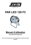
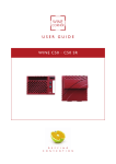
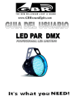
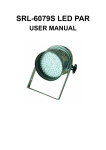
LEDPAR64 USER MANUAL 1 Table of Content Part I General Information 1.1 Introduction……………………………………………………………………………...3 1.2 Safety Information………………………………………………………………..……3 1.3 Unpacking…………………………………………………………………….………….4 1.4 Specifications……………………………………………………………….………....4 1.5 Features………………………………………………………………..………………4 Part II Installation and Operation 2.1 AC Power……………………………………………………………………………….5 2.2 Understanding DMX…………………………………………………………………....5 A. About DMX………………………………………………………………………...5 B. DMX Cable Requirement…………………………………………………………..5 C. Connection of DMX……………………………………………………………….5 D. DMX Addressing……………………………………………………………..……6 2.3 Operation Instructions…………………………………………………………..………7 A. Auto Mode……………………………………………………………...……..…..8 B. Sound Active Mode…………..…………………………………………..………8 C. Master/Slave Mode…………..…………………………………………..………8 D. DMX Mode……………………………….…………………………..….……..8 Part III Maintenance and Cleaning…………………………………………………….…….9 2 PART I GENERAL INFORMATION 1.1 Introduction Thank you very much for purchasing the LEDPAR64, our 5-channel LED Par Lamp series product that can work in AUTO, AUDIO and DMX mode. To assure reliable performance it designed to, please read the instructions in this manual thoroughly and carefully before application. 1.2 Safety Information The following definitions of identifying the severity of the hazards associated with the products are used: “DANGER” Imminently hazardous situation which, if not avoided, will cause death or serious injury. “WARNING” Potentially hazardous situation which, if not avoided, could cause death or serious injury. “CAUTION” Potentially hazardous situation which, if not avoided, may cause minor or moderate injury or property damage. In addition, it uses to alert against unsafe practice. IGNORING A HAZARD WILL VOID ANY WARRANTY. DANGER: Ensure that the fixture is disconnected from the main power before performing any type of service or any cleaning procedure. WARNNING: No serviceable parts inside the fixture, do not attempt to open it. WARNNING: The Installation must be performed by qualified professional in accordance with related local codes. WARNNING: Do not attempt to operate the fixture before read and understand the installation instructions and safety labels. CAUTION: Do not modify, alter, or attempt to service the LEDPAR64 CAUTION: Always ground (earth) the fixture electrically. CAUTION: Refer all service to a qualified technician. CAUTION: When suspending the fixture above ground level or place it on the ground, verify that the structure or surface can hold at least 10 times the weight of all installed devices. 3 3. Unpacking The LED PAR PRO DMX has been thoroughly tested and shipped in perfect operating condition. Check the shipping carton carefully for damage that may have occurred during shipping. If the carton appears to be damaged, carefully inspect your fixture for damage and be sure all accessories necessary to operate the fixture have arrived intact. In case damage has been found or parts are missing, please contact the sales person for further instructions. You can find the following components inside the box: ① . A set of LEDPAR64 ② . User Manual ③ . A 3-wire IEC power cable 4. Specifications: z z z z z Power Supply: AC120V/60Hz LED Configuration: 200PCS(R=80PCS 0.044w,G=66PCS 0.064w,B=54PCS 0.064w) Power Consumption: 19W Dimension (mm): L785XW145XH150 Weight: 2.8 kg Note: Power configuration may differ by regions. Please be sure the outlet in your area is suitable for the fixture. 5. Features: z z z z z z z z Low power consumption Maintenance free operation 100,000 hours rated LED lifespan 200 PCS of LED generates 16.7 million additive RGB colors DMX or stand-alone mode with Master/Slave function 18 built-in programs accessed via DMX-controller or manually Sound-activated via built-in microphone of adjustable sensitivity Brilliant light output 4 PART II Installation and Operation 2.1 AC power The fixture’s mains lead may require a grounding-type cord cap that fits your power distribution cable or outlet. Consult a qualified electrician if you have any doubts about proper installation. WARNNING: For protection from dangerous electric shock, the fixture must be grounded (earthed). The AC mains power supply shall have overload and ground-fault protection. CAUTION: Verify that the feed cables are undamaged and rated for the current requirements of all connected devices before use. Following the cord cap manufacturer's instructions, connect the yellow and green wire to ground (earth), the brown wire to live, and the blue wire to neutral. The table below details some pin identification schemes. Wire Pin Marking Screw color Brown Live “L” Yellow or brass Blue Neutral "N” Silver Yellow or green Ground 〨 Green 2.2 Understanding DMX A. About DMX DMX is the abbreviation of Digital Multiplex. It’s a universal protocol used by most audio, lighting and controller manufactures as a form of communication between fixtures and controllers. A DMX controller sends out DMX data instructions to the fixtures via 5-pin XLR cables. The data travels through the DMX chain as a serial data. DMX is a kind of "common language" allowing all products of different manufactures to be linked together and operate from a single controller, as long as all fixtures and the controller are DMX compatible. To ensure proper DMX data transmission, when using several DMX fixtures try to use the shortest cable path possible. B. DMX Cable Requirements: Your fixture, LEDPAR64 uses 3-pin XLR cable as connection media. C. Connection of DMX Connect the DMX XLR cable to the female 3-pin XLR output of your controller and the other side to the male 3-pin XLR input of the fixture (please refer to the figure below). You 5 must chain multiple fixtures together through serial linking, never split your DMX connections unless you are using our splitter/signal amplifier such as SRL-144. D. DMX addressing All fixtures should be given a DMX starting address when using a DMX controller, so the correct fixture responds to the correct control signal. This digital starting address is the channel number from which the fixture starts to "listen" to the digital control information sent out from the DMX controller. The allocation of this starting DMX address is achieved by various combining the dipswitches. This fixture employs 10 dipswitches to access its functions. Normally the dipswitches from #1 to #9 are used for encoding DMX address, the dipswitch #10 for enabling DMX mode. Dipswitch 1 address equals to 1 Dipswitch 2 address equals to 2 Dipswitch 3 address equals to 4 Dipswitch 4 address equals to 8 Dipswitch 5 address equals to 16 Dipswitch 6 address equals to 32 Dipswitch 7 address equals to 64 Dipswitch 8 address equals to 128 Dipswitch 9 address equals to 256 DMX address=Dipswitch 1+Dipswitch 2+…+Dipswitch 9. 6 2.3 Operation Instructions DIP SWITCH SETUP 1=ON Dip switch 0=OFF X= ON or OFF # #2 #3 #4 #5 #6 #7 #8 #9 #10 1 Function DMX Mode Dip 1~9 for DMX address setup Master Slave 1 X X X X X X X X X 0 X X X X X X X X X 1 1 0 0 0 0 0 X 1 0 AUTO Dip 1~3 for Setting Dip 5 & 6 Dip7 for with selection of 7 flashing for setting fade static colors or not: selection of 7-color ON for 4 speeds changing Stand Alone AUTO flashing or static colors Sound X X X X NOTES: DIP10 for setting Stand Alone or DMX/Slave mode. DIP 9 for setting AUTO or SOUND in Stand Alone mode. DIP 8 for setting fade effect in AUTO mode. DIP 7 for setting static color mode or color changing mode in AUTO. In static color mode, one can select single color using dip 1~3. Also, one can set DIP 4 to “ON” position for flash effect and DIP 5~6 for desired flashing speed. In color chasing mode, set DIP 5~6 for desired color changing speed. Static Color #1 0 1 0 1 0 1 0 1 #2 0 0 1 1 0 0 1 1 #3 0 0 0 0 1 1 1 1 Static Color RED GREEN BLUE YELLOW ORANGE PURPLE CYAN WHITE Flashing Speed #5 #6 0 0 1 0 SPEED HIGHEST MEDIUM 1 7 0 1 1 1 MEDIUM 2 LOWEST A. Auto mode When dipswitches #9 
 are both set at OFF, the fixture works in Auto mode. Please check above DIPSWITCH SETUP for reference. B. Sound Active mode When dipswitch #9 is ON and dipswitch #10 is OFF the fixture works in Sound active mode. Please check above DIPSWITCH SETUP for reference. C. MASTER/SLAVE Mode Master: set the dipswitch #10 of one LED PAR Light to OFF; the other dip switches 1-9 control the speed of the programs. Master mode has three working ways: auto with fade, auto without fade and sound. Please refer to DIPSWITCH SETUP above. Slave: set all the dip switch #1 & #10 to ON, #2-9 dip switches to OFF D. DMX mode When dipswitch #10 is set at ON, the fixture works in DMX mode. By various combining the Dipswitches #1 to #9 you can set the address ranging from 1 to 512. At this moment, the fixtures can be controlled by DMX controller or another fixture that has been designated as Auto or Sound Active mode with 5 channels receiving the data controlling the Red, Green, Blue, brightness and strobe rate output of the fixture respectively. Note: the address encoded by combining dipswitches #1 to #9 function as initial channel address. 8 PART III MAINTENACE AND CLEANING Please refer to the following points during the normal inspection: A. Be sure all screws and fasteners are securely tightened at all times. Lose screws may cause unexpected damage or injury. B. Electric power supply cables must not show any damage or frayed spot. CAUTION: Make sure that the power cord of the unit is disconnected from the mains before performing the following operation to avoid shock hazard! We recommend, if possible, frequent cleaning of the device, which will ensure its long lifespan and bright light output. While performing the cleaning, please always make sure that the power cord is disconnected from the mains and use a moist, lint-free cloth. Avoid using any alcohol or solvents, as they are harmful to the fixture. 9