1
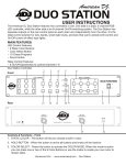
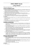
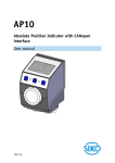
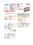
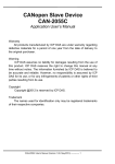
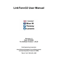
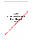
RP2D Series Remote I/O User Manual V2.1 User Manual RP2 Remote I/O Revision history Date Version 2010.04.08 V1.0 published 2011.02.10 V2.0 published 2011.02.16 V2.1 published 1 User Manual RP2 Remote I/O Safety precautions Please read this manual and the related data which mentioned in this manual carefully before using the product.Make sure the safety of proper operation. The instructions given in this manual are all about the product. Icons defined: Warning Avoid operational risk Be careful Be careful when operating Nonprofessionals forbid operating and installing •Before installation and wiring,make sure the power supply of the system be cut off, or it may result in electric block and the damage of the product •Keep any foreign matters(metal broken foil and wiring fragments .e.g.) from the model internal, these foreign matters may cause fire fault •Make sure the Communication cables and power cables are laid in the cable though or are clamped •The operating environment should satisfy the condition that mentioned in the user manual, or it may cause shock, fire, fault, and might damage the product, make the product can't reach the expected effect etc. •Install the module properly, or it may cause fault ,failure or falling of the module •Before installing and removing the module, make sure the internal power supply is cut off, or it may damage the module. •Don’t touch the conductive part or electronic components directly ,it may cause the fault or failure of the module •Before installing and removing the module, make sure the internal power supply is cut off, or it may damage the module or cause fault •Don’t touch the terminals when the power is on , or it may damage the module or cause fault. Please make sure the power is cut off before tightening the terminal screws or clearing the module and retightening the terminal screws. 2 User Manual RP2 Remote I/O Catalogue 1 Instructions ..................................................................................................................................... 4 1.1 An overview of the CANopen remote I/O .......................................................................... 4 1.2 Standards and specifications about the product .................................................................. 4 1.3 Product category distinguish ............................................................................................... 4 1.4 Kinco RP2 series remote I/O products list .......................................................................... 5 2 Technical characteristics ................................................................................................................ 5 2.1 The characteristics of CANopen ......................................................................................... 5 2.2 The configuration of Communication and device ............................................................... 6 2.3 Power, environment conditions and shell ........................................................................... 6 3 The connection Settings of CAN bus module ................................................................................ 7 3.1 Node ID settings.................................................................................................................. 7 3.2 The baud rate ....................................................................................................................... 7 3.3 Terminal resistances ............................................................................................................ 7 3.5 Service Data Objects (SDO) ............................................................................................... 8 3.6 Process Data Object (PDO) ............................................................................................... 10 3.7 NMT module control......................................................................................................... 10 3.8 Protection of NMT nodes .................................................................................................. 11 3.9 The Emergency ................................................................................................................. 12 4 Explain for LED indicate light ..................................................................................................... 13 5 Digital IO module ........................................................................................................................ 14 5.1 RP2D-1608C1, 16DI + 8DO DC 24V .............................................................................. 14 5.2. RP2D-0016C1, 16DO DC 24V……………………………………………………....18 6 Installation dimension:…………………………………………………………………………..20 3 User Manual RP2 Remote I/O 1 Instructions 1.1 An overview of the CANopen remote I/O Remote I/O is a kind of I/O system that provides fieldbus interface, it composed of various extension modules and bus interface modules, the protection grade is IP20, and it can be installed in the distribution cabinets or at the site for use. RP2 series CANopen I/O can communicate with other CANopen devices, and it accords with the CIA 301 and CIA 302 protocol standards. This module is suitable for I/O extension application of HMI, PLC which has CANopen function, for example machine control in factory automation field and small-scale process control. This module can satisfy the demands of the following application fields (But not limited to these applications): Packing machinery Textile machinery Building materials machinery Food machinery Plastic machinery CNC machine Printing machinery Central air conditioning Environmental protection equipment Single process control devices 1.2 Standards and specifications about the product Standard Scope IEC60529 Shell protection class protection product IEC 61131-2:Programmable controllers – Part 2: Equipment requirements and tests All the products RoHS : the Restriction of the use of certain hazardous substances in electrical and electronic equipment Material of the product class of the CIA DS401:Device Profile for Generic I/O Modules CIA DS301 : Electronic data sheet specification for CANOpen CANOpen 1.3Product Category distinguish The “product name “of the Kinco remote I/O module is used to express the main functions and use of the product .The product name is not unique,it is a generic terms of one kind of products “The product name” can be defined according to the following principles: 4 User Manual RP2 Remote I/O Chart 1 Name principles of RP2D 1.4 Product list of Kinco RP2 series remote I/O products Type Name Descriptions of function RP2D-1608C1 DC 24V power supply,DI 16×DC24V,DO 8×DC24V DO is Transistor output,rated output current for each channel is 0.5 A RP2D-0016C1 DC 24V power supply,DO 16×DC24V DO is Transistor output,rated output current for each channel is 0.5 A Digital IO module Form 1 Product list of RP2D series 2 Technical characteristics 2.1 The characteristics of the CANopen Communication norm accord with CiA 301 V4.02 Device norm accord with CiA 401 V2.1 status indication norm accord with CiA 303-3 V1.0 2 TPDO and 2 RPDO SDO-Server Life guarding, Node guarding, Heartbeat Producer Emergency Producer Minimum start capacity(slave) 5 User Manual RP2 Remote I/O 2.2 The configuration of Communication and device The CAN bus driver is Non-Current coupling.It can support 100 CAN nodes at one bus at most Set the node ID and baud rate by hardware switches The Bit Rate of the CAN bus: from 10kBit/s to 1Mbit/s High quality interface (lockable) When the error occurred it can send Emergency Messages 2.3 Power, environment conditions and shell Working voltage: 24V ±10%; Current consumption: 70mA Working temperature: -20°C to +65°C Storage temperature: -20°C to +90°C Dimention: (LxWxH in mm): 139.2×86.4×51 Weight: about 130g 6 User Manual RP2 Remote I/O 3 The connection Settings of CAN bus module 3.1 Node ID settings 1) Use the red dial switches (bit1-bit7) to set the station number, the node ID can not be the same in a same CANopen network ,its range is from 1 to 127. DIP1 DIP2 DIP3 DIP4 DIP5 DIP6 DIP7 Bit0 Bit1 Bit2 Bit3 Bit4 Bit5 Bit6 ON OFF OFF OFF OFF OFF OFF 1 OFF ON OFF OFF OFF OFF OFF 2 ON ON OFF OFF OFF OFF OFF 3 OFF ON ON ON ON ON ON 126 ON ON ON ON ON ON ON 127 Node ID Form 2 The code table of node ID 3.2 The baud rate Use the red dial switches (bit8-bit10 ) to set communication speed, the module’s communication speed must be the same in a same CANopen network DIP8 DIP9 DIP10 Bit0 Bit1 Bit2 OFF OFF OFF 10K ON OFF OFF 20K OFF ON OFF 50K ON ON OFF 125K OFF OFF ON 250K ON OFF ON 500K OFF ON ON 800K ON ON ON 1M Baud rate Form 3 The code table of the baud rate Note: Cut off the power and restart the I/O module after you’ve set the node ID and commutation speed 3.3 Terminal resistances There is no terminal resistances inside the module, so you should set a 120 ohms terminal resistances at the two sides of the network when you use it. 3.4 Connection of CAN bus The PIN name of the commutation bus terminal 7 User Manual RP2 Remote I/O Figure 2 The PIN of commutation bus terminal Descriptions of each pin’s function Serial number name descriptions 1 N/C NC 2 CAN_L Differential Signal of CAN 3 GND Low level power for CAN 4 N/C NC 5 N/C NC 6 GND Low level power for CAN 7 CAN_H Differential Signal of CAN 8 N/C NC 9 +24V +24V power for CAN Form 4 Description of the CAN bus terminal’s pins Note: It must be connected to external 24V power supply when it works 3.5 Service Data Objects (SDO) We use SDO to visit the Object Dictionary of a device, Visitors are called client.The CANOpen device,which the Object Dictionary is visited by and provide request service,is called server.The client’s CAN message and server’s response CAN message always includes 8 bytes data (Though not all the data byte is significative). A client request must have response from server. In the CANopen protocol, we can use SDO to change the content of the Object Dictionary, Following is the structure of the SDO command and standards that it follows : The basic structure of SDO: Client→Server/Server→Client Byte0 Byte1-2 Byte3 Byte4-7 SDO Command specifier Index of Object Sub-index of Object ** (** four bytes of data at most) Form 5 The basic structure of the SDO SDO command word contains the following information: Download / upload 8 User Manual RP2 Remote I/O Request /response Segmented / expedited transfer The length of CAN frame data byte ,it is used for toggle bit of every segment. SDO achieve five request/response protocols (1) Initiate Domain Download ;( 2) Download Domain Segment ;( 3) Initiate Domain Upload ;(4) Upload Domain Segment;(5) Abort Domain Transfer; § Download means the writing operations to the Object Dictionary; Upload means the reading operations to the Object Dictionary. §The grammar and details of SDO command word (the first byte in the SDO CAN message) is explained as following:(‘-’means unrelated ,it should be 0) §when reading the parameters, use the protocol of Initiate Domain Upload §when setting the parameters, use the protocol of Initiate Domain Download Initiate Domain Download 7 6 5 4 3 2 0 0 1 n 0 0 1 - Bit Client→ ←Server 1 e - 0 s - Description: n: means the byte number of insignificant data in the message [ The data from the (8-n) byte to the 7th byte data are insignificant ](n is effective when e =1 and s=1,or n=0). e: Transmit normally when e=1, transmit speedy when e=0 s: whether the length of the data is indicated, when s=0 it means the data length is not indicated ,s=1 means the data length is indicated e=0,s=0:it is reverved by CiA e=0,s=1:data byte is byte calculator, byte 4 is the Least Significant Bit (LSB),byte 7 is the most Significant Bit(MSB) e=1:The data byte is the data that will be downloaded (Initiate Domain Download) Bit 7 6 5 4 3 2 1 0 Client→ 0 0 1 - - - - - ←Server 0 0 1 - e s n Examples: ※ Read the parameters send SDO messages Identifier DLC 0x600+Node_ID 8 Daten 0 1 2 3 Send command Index of Subindex of word Object object 4 5 6 7 00 Receive SDO message Identifier DLC 0x580+Node_ID 8 Daten 0 1 2 3 Send command Index of Subindex of word Object object 4 (** four bytes of data at most) ※ Note: All the command word is 0x4 when SOD sends the message If data is one byte, then the receiving command word is 0x4F If data is two bytes, then the receiving command word is 0x4B If data is three bytes, then the receiving command word is 0x43 ※ When modify the parameters Send the SDO message 9 5 6 ** 7 User Manual RP2 Remote I/O Identifier Daten DLC 0 1 Send 0x600+Node_ID 8 command 2 3 4 Index of Sub-index of Object object word 5 6 7 6 7 ** (“**” four bytes of data at most) Receive the SOD message Identifier Daten DLC 0 1 Send 0x580+Node_ID 8 command 2 3 4 Index of Sub-index of Object object word 5 ** ※ Note: All the command word is 0x60 when SOD receives the message If data is one byte, then the sending command word is 0x2F If data is two bytes, then the sending command word is 0x2B If data is three bytes, then the sending command word is 0x23 3.6 Process data object (PDO) PDO is used to transmits process data among nodes, such as reading and setting I/O state of I/O module,collection and output of analogue and so on.. Considering the slaver limit, this protocol supports 4 groups of PDO,each group include a RPDO and a TPDO, we take RP2D-1608C1 I/O module for example to give some explains: Assuming the I/O module has16 input points and 8 output points, the 16 inputs are transmitted to the monitor terminal or other nodes via TPDO ,the 8 outputs are set by controlling terminal via RPDO. 0x180+NODE_ID,RPDO:0x200+NODE_ID,two bytes are enough used to express the value of 16 I/O, so sending and receiving PDO can be expressed as belows: (assume NODE_ID=1): 1. I/O node→monitor terminal(TPDO) COB-ID 0 byte 1 byte Data: input the I/O state variable 0x181 Input_Digital1 2. I/O node←monitor terminal(RPDO) 0 字节 COB-ID 0x201 Input_Digital2 1 字节 Data: output the I/O state variable Output_Digital1 Output_Digital2 3.7 NMT module control Only NMT-Master nodes can transmit NMT Module Control message. All the slave devices must support the NMT module control service. The message needn’t respond in NMT Module Control. The format of the NMT message is as follows: NMT-Master NMT-Slave(s) COB-ID Byte0 10 Byte1 User Manual RP2 Remote I/O 0x000 CS Node-ID Table 6 format of the NMT message When Node-ID=0,all the slave devices of NMT are addressed, CS is command word, it can take values as below: CS NMT service 0x01 Start Remote Node 0x02 Stop Remote Node 0x80 Enter Pre-operational State 0x81 Reset Node 0x82 Reset Communication Table 7 the range of CS command word 3.8 Protection of NMT nodes By the means of nodes protection service, the NMT master-node can check each node’s current state, This service is especially meaningful when these nodes have no data to transmit. The NMT-Master nodes send remote frame(no data) as follows: NMT-Master → NMT-Slave COB-ID 0x700+Node_ID The NMT-slave nodes send followings message to response: NMT-Master ← NMT-Slave Byte0 COB-ID 0x700 + Node_ID Bit 7 : toggle Bit6-0 : States The data part includes a trigger bit which must be set 0 or 1 alternately in each node protection. The trigger bit is set “0” in the first request of node protection. Bite 0~bite 6 means the state of nodes, they can take values in following form: State code Meanings of status code 0x00 Initializing 0x01 Disconnected * 0x02 Connecting * 0x03 Preparing 0x04 Stopped 0x05 Operational * 0x7F Pre-operational Form 8 description of the NMT node message Note:Only the nodes that support the expanding boot-up can provide the state with “*”.Notice that state 0 never appear in the node protection response, because nodes don’t response node protection message under this state. Or a node can be configured to produce periodic message called Heartbeat message Suppose NODE_ID=2 node→monitor terminal COB-ID 0 byte State of node 0x702 0x00 Then return the state is as follows: 11 User Manual RP2 Remote I/O State node Meanings of states code 0x00 Boot-up 0x04 Stopped 0x05 Operational 0x7F Pre-operational When a Heartbeat node start ,its Boot-up message is its first Heartbeat message . Heartbeat costumer usually is NMT-Master node who sets a timeout for each Heartbeat, and it take corresponding actions when time is out A node can not support Node guarding or Heartbeat protocol at the same time. 3.9 The Emergency When hardware or software errors are detected by nodes in the network, they can notify other nodes though the emergency, any internal error will be encoded into error code that defined and then transmitted to other nodes, if the errors are all corrected, then node will send a message with “no error” The emergency of CANopen contain the following types of error: Communication error: Frequent error when transmitting message Error that the CAN controller is broken away from the bus Overflow of sending buffer Overflow of receiving buffer Missing of message of Heartbeat or Life-guarding CRC error when transmit in the SDO module Application error Application error refers to short-circuit, underpressure, beyond the temperature limit, code or RAM error, etc Emergency message contains 8 bytes, the first and second bytes contains information that defined in the device specification, the third byte contains content of the error buffer, the remaining 5 bytes contains error information that defined by the device manufacture. Error information code of emergency state is stored at 1003h of Object dictionary index , errors will be written in the index according to time. The oldest error will occupy the highest position of sub index The format of emergency object message is as follows: Byte 0 1 2 3 4 5 6 7 content Code error Error register object Error area the manufacturer defined This module will support the error code as follows: Error code Description of error code 0x0000 Reset error or no error 0x1000 General error 0x3110 Input voltage is too high 0x3120 Input voltage is too low 0x3210 Internal voltage is too high 0x3220 Internal voltage is too low 0x5000 Errors of device hardware 0x6100 Errors of internal software of device 0x8110 CAN Overrun 12 User Manual RP2 Remote I/O 0x8120 Error Passive 0x8130 Life guard or Heartbeat error 0x8140 Recovered from bus-off 0x8210 PDO have not be dealt with because of length error 0x8220 Too long 0x9000 External error Form 9 error code 4 Description of LED indicate light We suggest two indicator lighter will be supported: one is red (ERR LED),the other id green (RUN LED).we can differentiate the following state by indicator’s state and flashing frequency: States Description ON The LED shall be constantly on. OFF The LED shall be constantly off. Flickering Shall indicate the iso-phase on and off with a frequency of approximately 10Hz:on for approximately 50ms and off for approximately 50ms Flickering Shall indicate the iso-phase on and off with a frequency of approximately 2.5Hz:on for approximately 200ms followed off for approximately 200ms. Single flash Double flash Shall indicate one short flash (approximately 200ms) follows by a long off phase (approximately 1000ms). Shall indicate a sequence of two short flashes (approximately 200ms),separated by an off phase (approximately 200ms).The sequence is finished by a long off phase (approximately 1000ms). Shall indicate a sequence of three short flashes (approximately 200ms),separated by an off phase (approximately 200ms).The sequence is finished by a long off phase (approximately 1000ms). Triple flash Form 10 state of indictor light CANopen Error LED The error LED of CANopen indicates the CAN physical layer’s condition, and indicate the error that caused the missing of CAN message(SYNG,GUARD,Hearttbeat).it is the red LED. numbers ERROR LED state 1 OFF No error descriptions Device is in working status. 13 User Manual 2 3 4 RP2 Remote I/O At least one of the error counters of the CAN controller has reached or exceeded the warning level (too many error frames) Single flash Warning limit reached Flickering AutoBitrate /LSS The auto-bitrate detection is in progress or LSS services are in progress(alternately flickering with run LED). Double flash Error control events A guard event (NMT-slave or NMT-master) or a heartbeat event (heartbeat consumer) has occurred. 5 Tripple flash Sync error 6 ON BUS-off The sync message has not been received within the configured communication cycle period time out(see object dictionary entry 1006H) CAN controller is bus off. Form 10 Status of error LED CANopen Run LED CANopen runs the state that LED indicate CANopen network state institutions, it is the green LED Number RUN LED status descriptions The auto-bitrate detection is in progress or LSS services are in progress (alternately flickering with error LED) 1 Flickering AutoBitrate/LSS 2 Single flash STOPPED 3 Blinking PRE-OPERATIONAL 4 ON OPERATIONAL The device is in state STOPPED The device is in the state PRE-OPERATIONA The device is in state OPERATIONAL Form 12 States of RUN LED 5 Digital IO module 5.1 RP2D-1608C1, 16DI + 8DO DC 24V The characteristics of DI channel Signal on site and internal signal is isolated by Photoelectric coupling technique A group of four channels use one common terminal, two common terminals are isolated from each other. A group of four channels can use both NPN and PNP input. The range of input level : 12~24VDC,input current>4mA Response time of input:10ms Each channel has its independent state indicator The characteristics of DO channel: 14 User Manual RP2 Remote I/O Signal on site and internal signal are isolated by Photoelectric coupling technique. The rated voltage supply is 24V DC. Each group has four channels outputs. The rated output current of each channel is 500mA. The maximum output frequency:1KH. Chart 3 RP2D-1608C1 15 User Manual RP2 Remote I/O Wiring diagram Chart 5 Wiring diagram of RP2D-0016C1 16 User Manual RP2 Remote I/O Object dictionary: Object Dictionary Object is index Object Name Data type 1000H Var Device type number Unsigned32 FALSE 1001H Var Error Register Unsigned8 TRUE 1005H Var Identifier SYNC-Message Unsigned32 FLASE 1008H Var Device description String FLASE 1009H Var Hardware Version String FLASE 100AH Var Software Version String FLASE 100CH Var Guard Time Unsigned16 FLASE 100DH Var Life Time Factor Unsigned8 FLASE 1014H Var Identifier Emergency Unsigned32 FLASE 1016H Array Consumer Heartbeat Time Unsigned32 FALSE 1017H Var Producer Heartbeat Time Unsigned16 FALSE 1018H Record Identity Object Identity FALSE 1029H Array Error Behavior Unsigned8 FALSE 1200H Record 1st Server SDO Parameter SDO Parameter FALSE 1400H Record RPDO1 Communication parameter PDOComPar FALSE 1401H Record RPDO2 Communication parameter PDOComPar FALSE 1600H Record RPDO1 Mapping parameter PDOMapPar FALSE 1601H Record RPDO2 Mapping parameter PDOMapPar FALSE 1A01H Record TPDO2 Mapping parameter PDOMapPar FALSE 6200H Array Write Output 8Bit Unsigned8 FALSE 6206H Array Error Mode Output 8Bit Unsigned8 FALSE 6207H Array Error Value Output 8Bit Unsigned8 Form 13 Object dictionary of Wiring diagram of RP2D-1608C1 17 mappable FALSE User Manual RP2 Remote I/O 5.2 RP2D-0016C1, 16DO DC 24V The characteristics of the DI channel The input signal and internal signal is isolated by Photoelectric coupling technique The rated voltage supply is 24V DC Each group has four routs output The rated output current of each rout is 500mA The highest output frequency:1KH Chart4 RP2D-0016C1 18 User Manual RP2 Remote I/O Wiring diagram Chart 5 Wiring diagram of RP2D-0016C1 Object dictionary Object Dictionary Object is index Object Name Data type 1000H Var Device type number Unsigned32 FALSE 1001H Var Error Register Unsigned8 TRUE 1005H Var Identifier SYNC-Message Unsigned32 FLASE 1008H Var Device description String FLASE 1009H Var Hardware Version String FLASE 100AH Var Software Version String FLASE 100CH Var Guard Time Unsigned16 FLASE 100DH Var Life Time Factor Unsigned8 FLASE 1014H Var Identifier Emergency Unsigned32 FLASE 1016H Array Consumer Heartbeat Time Unsigned32 FALSE 1017H Var Producer Heartbeat Time Unsigned16 FALSE 1018H Record Identity Object Identity FALSE 1029H Array Error Behavior Unsigned8 FALSE 1200H Record 1st Server SDO Parameter SDO Parameter FALSE 1400H Record RPDO1 Communication parameter PDOComPar FALSE 1401H Record RPDO2 Communication parameter PDOComPar FALSE 1600H Record RPDO1 Mapping parameter PDOMapPar FALSE 1601H Record RPDO2 Mapping parameter PDOMapPar FALSE 1A01H Record TPDO2 Mapping parameter PDOMapPar FALSE 6200H Array Write Output 8Bit Unsigned8 FALSE 6206H Array Error Mode Output 8Bit Unsigned8 FALSE 6207H Array Error Value Output 8Bit Form 14 Object dictionary of Unsigned8 RP2D-0016C1 FALSE 19 mappable User Manual RP2 Remote I/O 6 Installation dimension: Please observe the installation direction of I/O terminal, or it may cause failure. There should be prescriptive space between IO terminal and cabinet or other machines , or it may cause failure. The Installation dimension of RP2D-1608C as the following chart , RP2D-0016C1 and RP2D-1608C is the same dimension. 20 User Manual RP2 Remote I/O Kinco Automation (Shenzhen) Ltd. Add: 7/F, Bldg.9th, Software Park, Keji Central Road 2nd, Nanshan District, Shenzhen, China Tel: 86-755-26585555 Fax: 86-755-26616372 Http://www.kinco.cn Email: [email protected] 21