1
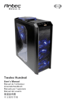
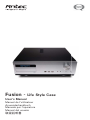
Fusion - Life Style Case User’s Manual Manuel de l’utilisateur Anwenderhandbuch Manuale per l’operatore Manual del usuario পᡅ䂀ᯢ At Antec, we continually refine and improve our products to ensure the highest quality. So it’s possible that your new case may differ slightly from the descriptions in this manual. This isn’t a problem; it’s simply an improvement. As of the date of publication, all features, descriptions, and illustrations in this manual are correct. Disclaimer This manual is intended only as a guide for Antec’s Computer Enclosures. For more comprehensive instructions on installing your motherboard and peripherals, please refer to the user’s manuals which come with your components and drives. Life Style Case Fusion User’s Manual The Power Supply Fusion comes with a 430Watt universal input, active PFC single 80mm fan cooled power supply with the newest ATX12V version 2.01 specifications. This include dual 12V output rails that delivers safer and more reliable output to your system’s components, as well as higher energy efficiency, which reduces power consumption by up to 25% saving you money on your electricity bill. In addition we’ve included a variety of industrial-grade protective circuitry: OPP (over power protection), OVP (over voltage protection), UVP (under voltage protection), and SCP (short circuit protection). The power supply comes with a main power switch. Make sure you turn the switch to the ON ( I ) position before you boot up your computer for the first time. Normally, you won't need to switch to the OFF (O) position, since the power supply includes a soft on/off feature. This lets you turn your computer on and off by using the soft switch on your computer case. If your computer crashes and you can't shut it down using the soft switch, you can switch the main power to the OFF (O) position to clear the fault, then reboot. The power supply features Power Factor Correction (PFC) circuitry in accordance with European standard regulation code EN61000-3-2. By altering the input current wave shape, PFC improves the power factor of the power supply. This results in increased energy efficiency, reduced heat loss, prolonged life for power distribution and consumption equipment, and improved output voltage stability. Together with the high efficiency design and the quiet 80mm fan, the power supply delivers not only cleaner but also quiet operating environment. Setting Up 1. Place the case upright on a flat, stable surface. 2. Remove the thumbscrews from the back of the top panel. Slide the panel towards the rear to remove it from the case. 3. Inside the case you should see the power supply, some wiring with marked connectors (USB, PWR etc.), and installed I/O panel and a power cord. 1 The Triple Chamber structure Upon opening the top panel, you will find the case is divided into three chambers – the power supply chamber, the motherboard chamber and the HDD chamber. This triple chamber structure isolates the heat and noise from each other resulting in much quieter and cooler operation than a traditional desktop case. Installing the Motherboard This manual does not cover CPU, RAM, or expansion card installation. Please consult your motherboard manual for specific mounting instructions and troubleshooting. The motherboard is located inside the main chamber with two 120mm TriCool™ fans preinstalled at the side of the case right next to the CPU to cool the hottest CPU on the market. 1. Lay the case down, with the open side facing up. The drive cages and power supply should be visible. 2. Make sure you have the correct I/O panel for your motherboard. If the panel provided with the case isn’t suitable, please contact your motherboard manufacturer for the correct I/O panel. 3. Line up your motherboard with the standoff holes, and remember which holes are lined up. Not all motherboards will match with all the provided holes; this is normal, and won’t affect functionally. (In other words, there will likely be extra holes.) 4. Remove your motherboard by lifting it up. 5. Screw the brass standoffs into the threaded holes that line up with your motherboard. Do not overtighten the standoffs. Some standoffs may be pre-installed for your convenience. 6. Place your motherboard on the brass standoffs. 7. Screw in your motherboard to the standoffs with the provided Philips-head screws. Your motherboard is now installed. Connecting the Power and LED The power supply conforms to the ATX12V Version 2.01 standard. It is also backwards compatible with most previous ATX12V form factor motherboards. Before you connect the power supply to any of your devices, please consult the appropriate user manuals for your motherboard and other peripherals. Note: this power supply does not provide a –5V line. Few modern motherboards (and none compliant with ATX12V v2.0 and above) require –5V power, but if yours does then this power supply may not be compatible with it. 1. Connect the 24-pin Main Power Connector and the 4-pin connector to your motherboard as needed. If your motherboard uses a Picture 1 Picture 2 20-pin connector; detach the 4-pin attachment on the 24-pin power connector (see pictures 1 and 2). 2. Connect the Reset switch (labeled RESET SW) to your motherboard at the RST connector. Make sure For 24-pin For 20-pin the label always faces the front of the case. motherboards motherboards 3. Power LED (labeled POWER LED) connector is located behind the Reset connector. 4. Power Switch (labeled POWER SW) connects to the PWR connector on the motherboard. 5. Hard Drive LED (labeled H.D.D. LED) connects to the IDE connector. 2 Connecting the USB Ports You will find a single 10-pin connector on a cable attached to the front USB ports. This is an Intel standard connector, which is keyed so that it can’t be accidentally reversed as long as it is connected to a proper Intel standard motherboard header. Connect the 10-pin connector to your motherboard headers so that the blocked pin fits over the missing header pin. Note: Please check your motherboard manual for your USB header pin layout and make sure it matches the attached table. If it does not match this Intel standard, please call Antec customer support at (800) 22ANTEC (North America) or at +31 (0) 10 462-2060 (Europe) to buy a USB adapter. This adapter will allow you to connect the front USB to your motherboard on a pin-by-pin basis. Motherboard Pin Layout 1 2 9 10 Pin Signal Names Pin Signal Names 1 USB Power 1 2 USB Power 2 3 Negative Signal 1 4 Negative Signal 2 5 Positive Signal 1 6 Positive Signal 2 7 Ground 1 8 Ground 2 9 Key (No Connection) 10 Empty Pin Connecting the IEEE 1394 (FireWire®, i.Link®) Port You will find a single 10-pin connector on a cable attached to the front IEEE 1394 connection. This is an Intel standard connector, which is keyed so that it can’t be accidentally reversed as long as it is connected to a proper Intel standard motherboard header. Connect the 10-pin connector to your motherboard header so that the blocked pin fits over the missing header pin. Note: Please check your motherboard manual for your IEEE 1394 header pin layout and make sure it matches the attached table. If you intend to connect the front FireWire port to an IEEE 1394 add-on card that comes with an external-type IEEE1394 connector, please call Antec customer service at (800) 22ANTEC (North America) or +31 (0) 10 462-2060 (Europe) to buy an adapter. This adapter will allow you to connect the front IEEE 1394 port to the external-type connector. Pin Assignment for Front Panel IEEE 1394 Connector 1 2 9 10 Pin Signal Names Pin Signal Names 1 TPA+ 2 TPA– 3 Ground 4 Ground 5 TPB+ 6 TPB– 7 +12V (Fused) 8 +12V (Fused) 9 Key (No Pin) 10 3 Ground Connecting the Audio Ports There is an Intel standard 10-pin connector (with 7 individual wires with connectors) coming out from the front panel speaker and microphone connection. If your motherboard supports Intel’s standard onboard audio connector, you can plug in the 10-pin connector directly onto the board. For non-Intel standard audio connection, you need to plug the 7 individual connectors to the motherboard. See instructions below: Locate the internal audio connectors from your motherboard or sound card. Consult your motherboard or sound card manual for the pin-out positions. 1. Microphone Signal Pin: Connect the MIC connector to this pin. 2. Microphone Power: Connect the MIC-BIAS connector to this pin. 3. Ground Pin: Connect the AUD GND connector to this pin. 4. Front Right Speaker Out Pin: Connect the FPOUT-R connector to this pin. 5. Front Left Speaker Out Pin: Connect the FPOUT-L connector to this pin. 6. Rear Right Speaker Out Pin: Connect the RET-R connector to this pin. 7. Rear Left Speaker Out Pin: Connect RET-L connector to this pin. The VFD Display/Volume Control Fusion comes with a Vacuum Fluorescent Display (VFD) and a volume control to work with your media center application. 1. Make sure the power supply is off and unplugged before installing any hardware. 2. Connect the 4 pin power cable from the VFD to the power supply 4 pin (Floppy) connector 3. Your VFD comes with a 4 pin internal USB adapter (see picture 3) and standard external USB connector (Default). Picture 3 4. 5. 6. 7. a) To use the external connector to connect to a standard USB port or: b) Check your motherboard USB header pin layout. Match the internal adapter to your motherboard header. Plug the internal adapter into the external connector and plug it in to your motherboard’s USB header. Plug in your power supply, and turn it on. Boot up your computer. Insert the provided driver CD into your optical drive. Restart again after the driver has been installed. Note: This VFD is intended to be compatible with Microsoft MCE. The basic features include: System Information, Media Information, E-mail check, Daily news, City information (weather report), and graphic equalizer. Hard disk Drive Installation There is a hard disk drive bracket with soft silicone grommets inside the HDD chamber. It can hold two hard drives. 1. Remove the HDD bracket from the chamber by removing the two screws on top of it. 4 2. Mount the left side of your hard drives (facing from the front of the hard drive) onto the drive bracket through the top silicone grommets with the special screws provided (see picture 4). Don’t over-tighten. Over-tightening the screws will harm the vibration and noise reducing ability of the silicone grommets. 3. Drop the HDD/bracket assembly back into the case. Each hard drive should rest on two soft silicone grommets preinstalled at the bottom of the case. 4. Fasten the bracket using the screws provided. 5. Find a 4-pin Molex or a SATA connector on the Picture 4 power supply and connect it to the male 4-pin connector on the device. 5.25” Device Installation This case comes with one 5.25” external drive bay right under the VFD. To install the external 5.25” device: 1. Remove the flip-up drive cage. 2. Insert the 5’25” device into the lower 5.25” drive bay of the cage. Make sure to use the rear set of screw holes on the cage to mount the device. Fasten the drive with the screws included. (See Picture 5) Note: the upper 5.25” drive bay is reserved for VFD. Do not mount any device into this Picture 5 bay. 3. Find a 4-pin Molex connector on the power supply and connect it to the male 4-pin connector on the device. Cooling System The 120mm TriCool™ fans The Fusion comes with two 120mm TriCool™ fans preinstalled at the side of the case inside the motherboard chamber. These two fans sit right next to the CPU to cool the hottest CPU on the market. Note: The default setting of the fan is Low. We recommend this speed for maximum quiet computing. This fan has a three-speed switch that lets you choose between quiet, performance, or maximum cooling. (See specifications below.) The fan is installed so that the air is blowing out of the case. Connect a large 4-pin connector from the power supply to the male 4-pin connector on the fan. Note: The minimum voltage to start the fan is 5V. We recommend that our users set the fan speed to High if you choose to connect the fan to a fan control device or to the Fan-Only connector found on some Antec power supplies. A fan-controldevice regulates the fan speed by varying the voltage to it. The voltage may start as low as 4.5V to 5V. Connecting a TriCool™ set on Medium or Low to a fan-control device may result in the fan not being able to start. The already lowered voltage from the fan control device will be further reduced by the TriCool™ circuitry below 5V. 5 Specifications: Size: Rated Voltage: Operating Voltage: Speed Input Current 120 x 120 x 25.4mm DC 12V 10.2V ~ 13.8V Air Flow Static Pressure Acoustical Noise Input Power High 2000 RPM 0.24A (Max.) 2.24 m³ / min (79 CFM) 2.54 mm-H2O (0.10 inch-H2O) 30 dBA 2.9 W Medium 1600 RPM 0.2A 1.59 m³ / min (56 CFM) 1.53 mm-H2O (0.06 inch-H2O) 28 dBA 2.4 W Low 1200 RPM 0.13A 1.1 m³ / min (39 CFM) 0.92 mm-H2O (0.04 inch-H2O) 25 dBA 1.6 W The Bottom Air Intake There are intake vents at the bottom of the case right under the HDD chamber. Fresh cool air will flow through the vents through the hard drives, and then flow into the motherboard chamber and exhaust by the two 120mm TriCool™ fans. Note: do not place the Fusion on a soft surface or over anything that will block the bottom air vents The Upper Air Intake There are vents on the top panel above the PCI expansion slot. Fresh cool air will flow through it into the motherboard chamber to cool the hottest VGA card. Note: do not place anything on top of the Fusion that will block the top air vents The Rear Air Intake There are vents right above the rear I/O panel and on the PCI expansion slot covers to bring in fresh cool air to help cool the CPU and VGA card. CPU Air Guide Integrated with the CPU Air Guide, fresh air from the rear air intake can be directed to the CPU cooler to enhance the CPU cooling. CPU Guide consists of several sections which can be adjusted by adding or removing it to best suit each individual motherboard CPU position. The Power Supply Air Intake There are vents on the left side of the case to bring fresh cool air into the power supply chamber to cool the power supply. Note: please leave at least 1” (2.5cm) between the left side of the case and anything that could block airflow to the power supply. This is required so that the power supply will have sufficient cooling. 6 Antec, Inc. 47900 Fremont Blvd. Fremont, CA 94538 USA tel: 510-770-1200 fax: 510-770-1288 Antec Europe B.V. Sydneystraat 33 3047 BP Rotterdam The Netherlands tel: +31 (0) 10 462-2060 fax: +31 (0) 10 437-1752 Customer Support: US & Canada 1-800-22ANTEC [email protected] Europe +31 (0) 10 462-2060 [email protected] www.antec.com © Copyright 2006 Antec, Inc. All rights reserved. All trademarks are the property of their respective owners. Reproduction in whole or in part without written permission is prohibited. Printed in China. Version 1.0.1 03/02/2006