1
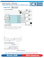
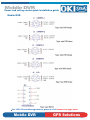
Mobile DVR
Power and wiring center quick installation guide
Mobile DVR
MD-01 1 channel
MD-04 4 channel
Note:
• This unit is for vehicles with a 12-volt battery and negative grounding. Before installing it in
arecreational vehicle, truck, or bus, check the battery voltage.
• To avoid shorts in the electrical system, be sure to disconnect the - battery cable before
beginning installation.
• Refer to the owner’s manual for details on connecting the power amp and other units, then
make connections correctly.
• Secure the wiring with cable clamps or adhesive tape. To protect the wiring, wrap adhesive
tape around them where they lie against metal parts.
• Route and secure all wiring so it cannot touch any moving parts, such as the gear shift,
handbrake and seat rails. Do not route wiring in places that get hot, such as near the
heater outlet. If the insulation of the wiring melts or gets torn, there is a danger of the wiring
short-circuiting to the vehicle body.
• Don’t pass the yellow lead through a hole into the engine compartment to connect to the
battery. This will damage the lead insulation and cause a very dangerous short.
• Do not shorten any leads. If you do, the protection circuit may fail to work when it should.
• Never feed power to other equipment by cutting the insulation of the power supply lead of
the unit and tapping into the lead. The current capacity of the lead will be exceeded, causing
overheating.
• When replacing fuse, be sure to use only fuse of the rating prescribed on this unit.
• When the DVR’s source is switched ON, a control signal is output through the blue/white lead.
This control signal can activate Power and Wiring Center to supply power to LCD, Cameras,
and GPS module.
• To avoid short-circuiting, cover the disconnected lead with insulating tape. Especially, insulate
the unused cemera leads without fail. There is a possibility of short-circuiting if the leads are not
insulated.
• If this unit is installed in a vehicle that does not have an ACC (accessory) position on the
ignition switch, the red lead of the unit should be connected to a terminal coupled with ignition
switch ON/OFF operations. If this is not done, the vehicle battery may be drained when you
are away from the vehicle for several hours. (Fig. 1)
For GPS Fleet Management, please visit www.usa-gps.com
Mobile DVR
GPS Solutions
Mobile DVR
Power and wiring center quick installation guide
Mobile DVR
MD-01 1 channel
MD-04 4 channel
1. Quick Install diagram
Type: mini DIN female
For GPS Fleet Management, please visit www.usa-gps.com
Mobile DVR
GPS Solutions
Mobile DVR
Power and wiring center quick installation guide
Mobile DVR
For GPS Fleet Management, please visit www.usa-gps.com
Mobile DVR
GPS Solutions