1
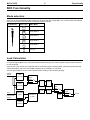
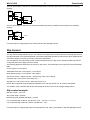
SDC Subaru Diff Controller User Manual Copyright – MoTeC Pty Ltd – 2001-2008 The information in this document is subject to change without notice. While every effort is taken to ensure correctness, no responsibility will be taken for the consequences of any inaccuracies or omissions in this manual. 22 February, 2008 Contents Introduction .......................................................................................................... 1 SDC Functionality ................................................................................................ 2 Mode selection ................................................................................................................................................... 2 Lock Calculation ................................................................................................................................................. 2 Slip Control ......................................................................................................................................................... 3 Slip control example ................................................................................................................................ 3 Diff Control Methods ........................................................................................................................................... 4 Current Control ....................................................................................................................................... 4 Duty Cycle Control .................................................................................................................................. 4 Speed Measurement .......................................................................................................................................... 4 Speed Calculations ................................................................................................................................. 4 Throttle Calibration ............................................................................................................................................. 5 Communications ................................................................................................................................................ 5 Miscellaneous functions ..................................................................................................................................... 5 Handbrake Timeout ................................................................................................................................ 5 Diff Temperature Override ...................................................................................................................... 5 Fault indication ........................................................................................................................................ 6 ABS input ................................................................................................................................................ 6 SDC Manager ....................................................................................................... 7 Computer requirements...................................................................................................................................... 7 Connecting to a SDC.......................................................................................................................................... 7 Installing SDC Manager ..................................................................................................................................... 7 Managing Configurations ................................................................................................................................... 7 Changing Configurations .................................................................................................................................... 7 User Mode Tables ................................................................................................................................... 7 File | Setup | Input ................................................................................................................................... 8 File | Setup | Output ................................................................................................................................ 9 File | Setup | User Modes ...................................................................................................................... 10 Sending Firmware ............................................................................................................................................ 10 SDC Installation ................................................................................................. 12 Appendices......................................................................................................... 13 Appendix A – Fault Codes ................................................................................................................................ 13 Appendix B – SDC Pinout and Links ................................................................................................................ 14 SDC Connector Pinout .......................................................................................................................... 14 Links...................................................................................................................................................... 15 Appendix C – CAN Wiring Practices ................................................................................................................ 16 Appendix D – Removing ABS systems ............................................................................................................ 17 Method 1: Partial ABS Removal ............................................................................................................ 17 Method 2: Full ABS Removal ................................................................................................................ 18 Appendix E - Communications Wiring .............................................................................................................. 19 Appendix F – CAN Messages .......................................................................................................................... 20 50Hz Messages .................................................................................................................................... 20 25Hz Messages .................................................................................................................................... 21 MoTeC SDC 1 Introduction Introduction The Subaru Diff Controller (SDC) is a direct replacement for the Driver Controlled Centre Diff (DCCD) controller in the 2003 WRX STi and similar vehicles. This manual covers the installation, configuration and functionality of the SDC. MoTeC SDC 2 Functionality SDC Functionality Mode selection There are six user selectable control modes, four of which are user configurable. The control modes are selected using the thumbwheel, and indicated on the dash board as follows: Thumbwheel Dash Light L LOCK L ▼ ▼ ▼ ▼ SDC Mode 100% lock User Mode 4 User Mode 3 User Mode 2 User Mode 1 0% lock Lock Calculation Lock percentage applied to the centre diff is determined primarily by the vehicle speed, throttle position and front to rear wheel slip. Each the four user modes are configured with an acceleration table, a braking table, a desired slip table and slip control parameters. Slip control and ABS override may be disabled if not required. The lock percentage for a user mode is determined according to the following strategy: Vehicle Speed Accel table (% lock) Brake OFF ON + Brake table (% lock) MIN ABS OFF TPS Desired Slip table (kph) Front & Rear Speed Slip control params 100% Lock Slip Calculation (% lock) 5% Lock ON Handbrake OFF 0% Lock ON % lock MoTeC SDC 3 Functionality The lock percentage for the full lock mode (thumbwheel fully forward) is determined according to the following strategy: 100% Lock ABS OFF 5% Lock ON Handbrake OFF 0% Lock ON % lock The lock percentage for the zero lock mode (thumbwheel fully back) is determined according to the following strategy: 0% Lock ABS OFF 5% Lock ON % lock For information on configuring the user modes see the SDC Manager section. Slip Control The slip control strategy detects slip (ie: rear speed ≠ front speed) and increases diff lock to maintain slip close to the value specified in the Desired Slip table. The Desired Slip table specifies the value above which additional diff lock will be applied, according to the slip control setup parameters. The calculation of lock percentage for slip control is determined by the Slip Control Range and Max Slip Control Lock parameters which apply to all user modes. The following algorithm determines the %lock for slip control. The desired slip is the output from the Desired Slip table. IF Rear Speed > Front Speed THEN Measured Slip = Rear Speed – Front Speed ELSE Measured Slip = Front Speed – Rear Speed Slip Control Factor = (Measured Slip – Desired Slip) / Slip Control Range Constrain Slip Control Factor to the range 0 to 1 Slip Diff Lock = Slip Control Factor * Max Slip Control Lock NOTE: Slip is specified as speed difference between front and rear wheels, not as a ratio of the speeds. The addition of the calculated slip diff lock percentage is shown in the lock percentage strategy above. Slip control example Max slip control = 10% lock Slip control range = 20 km/h Desired slip (from Desired Slip table) = 10km/h For a measured slip of 15km/h, slip diff lock = ((15 – 10) / 20) * 10 = 2.5% For a measured slip of 30km/h or above, slip diff lock = 10% For information on configuring the slip control parameters, see Setup | User Modes in the SDC Manager section. MoTeC SDC 4 Functionality Diff Control Methods The SDC implements two methods of driving the centre differential, selectable in the configuration. Current Control Current output control regulates the solenoid current waveform by setting a minimum current and ripple factor for a particular lock percentage. The parameters for this control mode are pre-configured for the factory centre diff solenoid and should not be changed. This is the recommended mode of operation. Duty Cycle Control Duty cycle output control provides a PWM solenoid drive from 0 to 100% duty cycle for 0 to 100% calculated lock. The frequency of the drive pulses changes linearly between specified frequencies for 0% 100% lock. This mode is not recommended as the effective diff lock will change with diff temperature. An absolute limit for solenoid current can be configured for either control method, and is pre-configured for the factory centre diff solenoid. For information on configuring the diff control method, see Setup | Output in the SDC Manager section. Speed Measurement The SDC can be configured to use up to four wheel speed sensors, or the tacho input to calculate speeds. The wheel speed inputs can be configured as hall effect or magnetic sensors with adjustable thresholds, and individual sensors can be enabled or disabled. The speed calibration can be adjusted for different wheel sizes and sensor teeth. Magnetic sensor input thresholds are individually configurable for front and rear sensor pairs according to the current front and rear speeds. The tacho input can be configured and calibrated as the speed input for cars using non-standard wiring. This configuration is not recommended as slip control cannot be implemented with a single only speed input. The default SDC configuration settings are suitable for the standard factory wiring, where the four wheel speed sensors are conditioned by the ABS unit. Magnetic setup is required when the ABS unit is not present. Front, rear and vehicle speeds are calculated from the wheel speeds, and all speeds are transmitted in CAN messages for logging by the ADL (Advanced Dash Logger). For information on configuring speed inputs, see Setup | Input in the SDC Manager section. Speed Calculations The method of calculating front, rear and vehicle speeds is dependent on the status of the brake input. When the foot brake is applied, speeds are calculated as follows: Front Speed is the faster of the two front wheel speeds. Rear speed is the faster of the two rear wheel speeds. Vehicle speed is the faster of the calculated front speed and rear speed. When the foot brake is not applied, speeds are calculated as follows: The front speed is the average of the two front wheel speeds, weighted 80% towards the slowest front wheel speed. If one front wheel speed is less than half of the other front wheel speed, then front speed is simply the faster of the two front wheel speeds. The rear speed is the average of the two rear wheel speeds, weighted 80% towards the slowest rear wheel speed. If one rear wheel speed is less than half of the other rear wheel speed, then rear speed is simply the faster of the two rear wheel speeds. The vehicle speed is the average of the front and rear speeds, weighted 80% towards the slowest speed. If either the front or rear speed is less than half of the other speed, then vehicle speed is simply the faster out of the front speed and rear speed. If any wheel speed exceeds 300km/h, the sensor reading is ignored until its speed returns to below 300km/h for 2 seconds. This is to prevent erratic behaviour from noisy wiring or faulty sensors. MoTeC SDC 5 Functionality Throttle Calibration The throttle position sensor input can be calibrated using a table to convert voltage to throttle position. This allows non-linear calibration of throttle position to more closely model the change in torque vs throttle butterfly angle. The SDC configuration program allows throttle input voltages to be read from the SDC to perform 0% and 100% calibrations. For information on calibrating the throttle input, see Setup | Input in the SDC Manager section. Communications The SDC communicates over a 1Mbit/sec CAN bus. The SDC is typically connected to a CAN bus using a MoTeC OEM Communications cable that plugs into the SDC board. This cable also provides the power required if the MoTeC CAN cable is used to interface with a PC. An alternative method of CAN wiring is to use the communications pins on the SDC connector and modify the existing vehicle communications wiring for use as a CAN bus. This is only recommended for advanced users. To use the connector pins for CAN there are two links that must be closed on the SDC board - see Appendix B – SDC Pinout and Links and Appendix E - Communications Wiring for details. The SDC transmits CAN messages at 50Hz containing information about all input and output functions, such as speed readings, diff currents, duty cycles etc. The SDC transmits CAN messages at 25Hz containing diagnostic information such as fault flags, firmware versions etc. To configure an ADL to receive SDC messages, use the ‘SDC’ and ‘SDC Diagnostics’ communications templates included with Dash Manager. The transmission of CAN messages can be disabled. This feature may be used to prevent reverse engineering of user control modes. The CAN bus is also used for communication with a PC for configuration and upgrading firmware using the MoTeC UTC (USB To CAN) adaptor or the MoTeC CAN cable. See Appendix C – CAN Wiring Practices for recommended CAN wiring practices Miscellaneous functions Handbrake Timeout With the standard STi wiring loom, the handbrake input pin to the SDC may be pulled low in any of the following situations: Handbrake on ABS computer fault Brake pressure fault To prevent the diff staying at 0% lock due to an ABS fault or Brake pressure fault, the handbrake input is ignored by the SDC if the handbrake input is on (ie low) for more than 10 seconds while the vehicle speed is above 5kph. The handbrake input is then ignored until it goes off (ie high) again. See Appendix D – Removing ABS systems for information on preventing ABS faults from disabling the handbrake input in advanced applications where the ABS solenoids and valve block are removed. Diff Temperature Override The diff temperature override functionality allows a specified control mode to be used if the rear diff overheats. If this functionality is enabled, the current user control mode (1-4) is overridden with the configured override mode (0%,100% or one of the 4 user modes) while the rear diff temperature input is active. The diff temperature override does not occur if the thumbwheel is in the full lock or open lock positions. To prevent rapid transitions between control modes when the diff heats or cools, the diff temperature input must be stable in a new state (high or low) for 2 seconds before the input is considered to have changed. MoTeC SDC 6 Functionality For information on configuring the diff temperature override, see Setup | User Modes in the SDC Manager section. Fault indication Faults are indicated by the flashing of a mode light on the dash. The light will continue to flash until there have been no faults present for 2 seconds. Fault codes and diagnostic codes are included in the CAN diagnostic messages, as described in Appendix A – Fault Codes. ABS input The ABS pin on the SDC connector is used by default as an ABS status input. If the link LK07 on the SDC board is closed, the ABS pin can be used as a 0volt reference for magnetic speed sensors. See Appendix B – SDC Pinout and Links for link details. The ABS input functionality should be disabled if the pin is reassigned as a 0volt pin or if the ABS input is not required. See Setup | Input in the SDC Manager section. MoTeC SDC 7 Setup SDC Manager The SDC Manager software is necessary to configure an SDC unit from a PC. A new SDC unit must be configured before its initial use. Computer requirements The SDC Manager software runs under Windows 95, 98, ME, NT4, 2000 or XP operating systems. The minimum recommended PC specification is a Pentium 90 with 16MB RAM and a parallel port. Connecting to a SDC The SDC connects to the PC using either the MoTeC UTC (USB To CAN) adaptor or the MoTeC CAN cable connected to the PC parallel port. The SDC unit must be powered to communicate with the PC. Installing SDC Manager The SDC software can be installed either from the MoTeC Resource CD supplied with the SDC, or from the MoTeC website (software.motec.com.au). To start the program after installation, click on Start Programs MoTeC SDC Manager SDC Manager 1.1 Managing Configurations An SDC configuration file determines exactly how the SDC unit will operate. The SDC Manager software allows configurations to be created, edited and sent to the SDC. To prevent unauthorized copying of configuration data, configurations cannot be read out of the SDC. To create a new configuration, select File | New from the main menu, or use the default configuration created on startup. The default configuration has similar behaviour to the manual modes in the factory controller. If the SDC2 is not connected to the PC when SDC Manager is started or when new configuration is created, then the user must select the configuration type (SDC) when prompted. To open an existing configuration file, select File | Open from the main menu and select the desired file. After a configuration has been created or modified it should be saved with a meaningful name by selecting File | Save or File | Save As from the main menu. To send the currently opened configuration to the SDC, select File | Send Config from the main menu, or press F5. The configuration is automatically saved to disk when sent to the SDC. A new configuration must be saved with a new name before it can be sent. Changing Configurations User Mode Tables The four user mode each has a set of three tables that determine the diff lock characteristics for the mode. The speed and throttle position axis values used for all user mode tables are configurable under the File | Setup option in the main menu, and can have between 2 and 11 values. Linear interpolation is used between table points. The Acceleration table is used to generate the %lock when the foot brake is not applied. The Braking table is used to generate the %lock when the foot brake is applied, and is an override table for the Acceleration table values. If a cell in the braking table is left blank, the corresponding cell value from the Acceleration table is used. Cell values should only be entered into the Braking table where a different value is required from the Acceleration table. MoTeC SDC 8 Setup The Desired Slip table specifies the value above which additional diff lock will be applied, according to the slip control setup parameters. The Acceleration and Braking tables specify %lock in 0.5% units. The Desired Slip table specifies desired slip in 0.1 km/h units. For more information on the diff control strategy, see the SDC Functionality section. Editing Tables Cell values in the tables may be incremented/decremented using the Page Up/Page Down keys, or entered directly. Table regions may be selected, cut, copied and pasted within the application, or to an Excel spreadsheet. An entire table region can be filled with a value by selecting the region, entering the value, then pressing Enter. Basic maths operations can be performed on a single cell or an entire table region. To perform an operation on all cells within a region, select the region then enter the number followed by the operator (+,-,/,*). Examples: To add 15 to all values in a region, select the region then type 15+ To multiply all values in a region by 0.8, select the region then type 0.8* Mode Notes Comments about each user mode may be entered in the Notes field, and are stored with the configuration. User Mode Table Font The font type and size for the User Mode Tables may be changed using the File | Select Font option. File | Setup | Input Setup Speed The speed detection method (Wheel Speed or Tacho) must be selected, and the appropriate parameters are shown for the speed detection method. Speed Calibration For Wheel Speed speed measurement method. The speed calibration applies to all four wheel speed inputs. Pulses/revolution: Number of sensor pulses per wheel revolution Circumference units: Units (mm or inches) used to specify the rolling circumference Rolling circumference: Tyre rolling circumference, specified in mm or inches Speed Sensor For Wheel Speed speed measurement method. Hall/Magnetic: If the speed sensor type is hall effect (or equivalent), a hall switching threshold must be specified. If the speed sensor type is magnetic, the Magnetic Levels table (File | Setup | Input Tables) must be configured. Factory default is Hall. Hall threshold: The switching threshold for hall effect speed sensor inputs. Factory default is 2.2V. Sensor Enable: MoTeC SDC 9 Setup The four speed sensors (Front Left, Front Right, Rear Left and Rear Right) can be individually enabled or disabled. A disabled sensor has a speed of 0km/h. Factory default is all sensors enabled. Tacho Calibration For Tacho speed measurement method. Pulses per 100m: Specify the number of tacho input pulses per 100 metres rolling distance . Enable ABS Input If the ABS input is enabled then the ABS active input from the ABS computer is used as described in the diff control strategy in the SDC Functionality section. The ABS input should be disabled if the ABS system is removed or disabled, or if the ABS input pin is used as a sensor 0v by closing link LK07 on the SDC board. File | Setup | Input Tables Magnetic Levels For Wheel Speed speed measurement method. If magnetic wheel speed sensors are used, the sensor thresholds must be specified in the magnetic levels table. Thresholds are configured separately for front and rear sensors. Up to 11 ascending speeds can be specified in the table and linear interpolation is used between points. Throttle Position The Throttle Position table allows the throttle position sensor to be calibrated in up to 11 steps, with linear interpolation between points. The table specifies the throttle position characteristic between the TP Low voltage (0%in) and the TP High voltage (100%in). The Read buttons for the throttle sensor high and low voltages can be used to calibrate the sensor if the SDC is powered and connected to the PC. To calibrate, press the TP High Read button with the throttle pedal fully depressed, then press the TP Low Read button with the throttle pedal fully released. File | Setup | Output Setup Output Control The output control method can be configured as Duty cycle or Current control, as discussed under Diff Control Methods in the SDC Functionality section. The default output control parameters should only be changed by advanced users. Duty Cycle control is not recommended as the effective diff lock will change with diff temperature. Full Lock Frequency: Open Lock Frequency: If duty cycle diff control is used, the diff drive frequency varies between the Open Lock Frequency at 0% diff lock and Full Lock Frequency at 100% diff lock. Full Lock Current: The full lock current is the target diff current for a desired 100% diff lock. The target diff current varies linearly between 0A for 0% lock and Full Lock Current for 100% lock. The factory default is 5.0A. This parameter should only be changed by advanced users. Min Pulse Width: Max Pulse Width: The width of the diff control pulses varies linearly with the desired diff lock, from Min Pulse Width at 0% lock to Max Pulse Width at 100% lock. The factory default is 80μS to 800μS. MoTeC SDC 10 Setup These parameters should only be changed by advanced users. Output Current Protection: The diff current output is hardware limited to a maximum of Output Current Protection Amps, regardless of the control method used. If the Current Control method is used, this current must be at least one Amp higher than the Full Lock Current. The factory default is 11.0A. Allow CAN diagnostics The CAN data stream can be disabled or enabled. This feature may be used to prevent reverse engineering of user control modes. File | Setup | User Modes Lock Table Axis This parameter is always Throttle Position for an SDC. Slip Control Enable Slip Control: If slip control is enabled then the Desired Slip table and the slip control parameters are used to determine how much extra diff lock is applied to control wheel slip. If slip control is disabled then the Desired Slip table has no effect. Max slip control: This parameter specifies the maximum amount of diff lock (%lock) that can be added to attempt to control slip. Slip control range: This parameter is the amount of measured slip (km/h) above the desired slip at which the Max slip control lock will be applied. If the amount of measured slip is within the range (desired slip + slip control range), then the amount of slip diff lock applied is proportional to how far the measured slip is away from the desired slip. For more detail on slip control parameters, and slip control examples, see Slip Control in the SDC Functionality section. Diff Temperature Override Override mode: If this functionality is enabled, the current user control mode (1-4) is overridden with the configured override mode (Open, Locked or one of the 4 user modes) while the rear diff temperature input is active. For more detail on the temperature override functionality, see Diff Temperature Override in the SDC Functionality section. Speed Axis Up to 11 values can be specified for the speed axis that is used in all of the user mode Braking and Acceleration tables. The axis values must be ascending and duplicate values are not allowed. Spacing between values is not fixed, allowing non linear axes. Throttle Axis Up to 11 values can be specified for the throttle axis that is used in all of the user mode tables. The axis values must be ascending and duplicate values are not allowed. Spacing between values is not fixed, allowing non linear axes. Monitoring SDC Data Live data from a connected SDC may be monitored using the File | Monitor Channels option (or the ‘M’ hotkey) to open the Monitor Channels window. MoTeC SDC 11 Setup Sending Firmware The SDC firmware is user upgradeable from a PC connected to the MDC with the MoTeC UTC (USB To CAN) or the MoTeC CAN cable. To upgrade the firmware the SDC must be powered and connected to a PC with the SDC Manager software installed. Use File | Send Firmware to start to send the current firmware to the SDC. MoTeC SDC 12 Appendices SDC Installation The factory centre diff controller box is bolted to the steering column underneath the dashboard. A standard SDC installation involves the replacement of the factory circuit board, and the addition of a cable to connect the CAN bus. The CAN adaptor cable is not required if the vehicle wiring loom has been modified to use the CAN pins on the main SDC plug. To remove the controller, locate the box under the dash, unplug the loom and remove the single bolt holding the bracket. The controller box is shown below. To remove the factory circuit board, open the case lid (four screws) and undo the circuit board (3 screws). If a CAN cable is required, a cable entry hole should be made in the case before the SDC board is installed, and the CAN cable should be cable tied to the SDC board using the two holes provided. The cable tie and the recommended position for the cable entry hole are shown below. The SDC board is fastened using the 3 screws from the factory board. MoTeC SDC 13 Appendices Appendices Appendix A – Fault Codes The SDC fault flags included in the CAN diagnostics are sent as a bit field (16 bit) with the following faults: Bit 0 (0x0001 = 1) Bad Configuration (CRC failure) Bit 1 (0x0002 = 2) Short circuit diff solenoid Bit 2 (0x0004 = 4) Open circuit diff solenoid Bit 3 (0x0008 = 8) Output driver failure Bit 4 (0x0010 = 16) Diff Relay (in vehicle loom) stuck closed Bit 5 (0x0020 = 32) Current protection specified in the configuration is too high for the hardware revision The SDC diagnostic flags included in the CAN diagnostics are sent as a bit field (16 bit) with the following faults: Bit 0 (0x0001 = 1) Output circuit stopped Bit 1 (0x0002 = 2) Output limited to protection current limit MoTeC SDC 14 Appendices Appendix B – SDC Pinout and Links SDC Connector Pinout 20 1 40 21 Pin Function Notes 1 Diff mode 3 dash light output Active low 2 Diff mode 2 dash light output Active low 3 Diff mode 1 dash light output Active low 4 Diff open dash light output Active low 5 CAN-LO (if link LK01 closed) Open circuit if LK01 is open 6 CAN-HI (if link LK02 closed) Open circuit if LK02 is open 7 Rear diff temperature input 0V when temp high 8 AUTO/MANUAL switch input For future use 9 Brake pedal input 12V when brakes applied 10 ABS active input 0V when ABS active or 0V for magnetic wheel speed sensor inputs (if link LK07 closed) 11 Handbrake input 0V when handbrake ON 12 Thumbwheel input 0V (Open) 5V (Locked) 13 5V supply output Supply to thumbwheel and Gsensor 14 No connection 15 Battery + input Power for electronics 16 Battery + input Power for electronics 17 No connection 18 Diff power input Solenoid power from relay 19 Diff power input Solenoid power from relay 20 Diff Drive+ output Solenoid positive 21 Diff relay control output Solenoid power relay control 22 No connection 23 Diff locked dash light output Active low 24 Diff mode 4 dash light output Active low 25 No connection 26 Rear left speed sensor input Speed input (Magnetic or Hall) 27 Rear right speed sensor input Speed input (Magnetic or Hall) 28 Front left speed sensor input Speed input (Magnetic or Hall) MoTeC SDC 15 29 Front right speed sensor input 30 No connection 31 Tacho input 32 Throttle Position Sensor input 33 Lateral G input 34 0V 35 No connection 36 Battery- input Electronics ground 37 Battery- input Electronics ground 38 Diff ground input Solenoid ground 39 Diff ground input Solenoid ground 40 Diff drive- output Solenoid negative (switched) Appendices Speed input (Magnetic or Hall) 2 pulses/rpm from ECU 0V to thumbwheel and G-sensor Links There are four links on the back of the SDC circuit board to configure certain SDC functions. These links are open circuit by default, and can be soldered closed. Link Link Open Function Link Closed Function LK01 Pin 5 open circuit Pin 5 CAN-HI LK02 Pin 6 open circuit Pin 6 CAN-LO LK05 No CAN termination 100ohm CAN termination LK07 Pin 10 is ABS input Pin 10 is 0V (for use as a sensor ground when magnetic wheel speed sensors are used). If LK07 is closed, the ABS input should be disabled under the Setup | Input menu MoTeC SDC 16 Appendices Appendix C – CAN Wiring Practices The CAN bus should consist of a twisted pair trunk with 100R (0.25Watt) terminating resistors at each end of the trunk. The preferred cable for the trunk is 100R Data Cable but twisted 22# Tefzel is acceptable. The maximum length of the bus is 16m (50ft) including the MoTeC CAN Cable (PC to CAN Bus Communications Cable) CAN Devices (such as MoTeC ADL, M800 etc) may be connected to the trunk with up to 500mm (20in) of twisted wire. The connector for the CAN Communications Cable may also be connected to the trunk with up to 500mm (20in) of twisted wire and should be within 500mm of one end of the trunk. If desired two CAN Cable connectors may be used so that the MoTeC CAN Cable may be connected to either side of the vehicle. Both connectors must be within 500mm of each end of the trunk. Minimum one twist per 50mm (2in) CAN-HI CAN-LO 0V 8V CAN-HI CAN-LO CAN Device 500mm Max CAN-HI CAN-LO CAN-HI CAN-LO 100R 100R << CAN Bus >> 500mm Max 1 These wires must be Twisted CAN Cable Connector CAN-HI 5 CAN-LO 4 3 100R Terminating Resistors at each end of the CAN Bus CAN Device CAN Device 500mm Max Short CAN Bus If the CAN Bus is less than 2m (7ft) long then a single termination resistor may be used. The resistor should be placed at the opposite end of the CAN Bus to the CAN Cable connector. MoTeC SDC 17 Appendices Appendix D – Removing ABS systems The removal of the ABS valve block for weight saving in rally applications directly affects the speed inputs to the SDC. In the standard factory wiring, the magnetic wheel speed sensors are conditioned by the ABS controller and then passed on the diff controller. If the ABS system is removed, there are two possible methods for getting wheel speeds to the SDC. The first method is a partial removal of the ABS systems, retaining the ABS electronics and removing the solenoids and valve block. This is the recommended method. The second method is a full removal of the ABS systems, looping back the wheel speed pins at the ABS connector, and configuring the SDC to use magnetic sensors. Method 1: Partial ABS Removal Retaining the ABS electronics allows wheel speeds to pass through to the SDC without any wiring modifications. This is the recommended method for removing the ABS. The following steps detail modifications to remove all unnecessary ABS parts. Step 1: Remove the black electronic module from the valve block Step 2: Remove the 8 solenoids from the electronic module. The solenoid wires can be broken by working the solenoids back and forwards with pliers until the wire breaks under fatigue. Clean up any loose wires left on the module. Step 3: Cut off the plastic surround which enclosed the solenoids. This is an optional step for further weight reduction. Step 4: Break out pin 21 on the module connector by twisting the pin with pliers. This pin must be removed to prevent the ABS warning from turning on the brake warning, which also pulls down the handbrake signal into the diff controller. ABS module with the solenoids removed and the solenoids surround cut off. ABS module pins showing pin 21 removed MoTeC SDC 18 Appendices Removed solenoids and solenoid surround Method 2: Full ABS Removal If the ABS valve block and electronics are fully removed, the wiring for the speed sensor pins must be looped back at the ABS loom connector to directly connect the magnetic sensors to the SDC. To loop back the speed inputs, the ABS connector must be wired as shown: Function Pin Pin Function RL MAG + 7 19 RL to SDC RL MAG 0V 8 3 Sensor 0V to SDC pin 10 FR MAG + 11 16 FR to SDC FR MAG 0V 12 3 Sensor 0V to SDC pin 10 9 17 FL to SDC FL MAG 0V 10 3 Sensor 0V to SDC pin 10 RR MAG + 14 18 RR to SDC RR MAG 0V 15 3 Sensor 0V to SDC pin 10 FL MAG + Important! The ABS connector has an integrated shorting bar between pins 21 and 22 that is activated when the connector is unplugged from the ABS module. This shorting bar activates the ABS warning and the brake warning, which also activates the handbrake signal into the diff controller. If the ABS connector is retained on the loom, but is not plugged into the ABS unit, the shorting bar must either be cut, or securely jammed open in order for the SDC to operate correctly. Important! SDC link LK07 must be closed so that SDC pin 10 can be used as the sensor 0V The ABS input must be disabled in the SDC configuration The ABS loom connector is shown below: MoTeC SDC 19 Appendices Appendix E - Communications Wiring The factory wiring loom can be utilised for CAN communications by using the existing communication bus wiring to the dash mounted OBD-II connector (Subaru Data Link Connector B40) and the Check Connector (Subaru connector B79). To use the factory wiring, the links LK01 and LK02 on the SDC board must be soldered closed to connect CAN-LO and CAN-HI to SDC connector pins 5 and 6. With the links closed, the CAN bus is wired to the following connector pins: SDC Connector Data Link Connector Check Connector CAN-LO B289-5 B40-5 B79-10 CAN-HI B289-6 B40-4 B79-9 All pin numbers use the Subaru numbering conventions. For more detail, see the Subaru wiring diagrams. Note: The communications lines used for CAN are also connected to the ABS unit, however testing has shown that CAN operation on these wires does not interfere with the ABS systems. MoTeC SDC 20 Appendix F – CAN Messages The SDC operates on a CAN bus running at 1Mbit/s. SDC operational data messages are each transmitted at 50Hz. SDC diagnostic messages are each transmitted at 50Hz. 50Hz Messages CAN ID 0x1F4 Byte Bits 0 4..7 0..4 1 2 3 4 5 6 7 CAN ID 0x1F4 Byte Bits 0 4..7 0..4 1 2 3 4 5 6 7 CAN ID 0x1F4 Byte Bits 0 4..7 0..4 1 2 3 4 5 6 7 CAN ID 0x1F4 Byte Bits 0 4..7 0..4 1 2 3 4 5 6 7 Data Compound Id = 0 SDC Mode (Thumbwheel Position) 0 = Diff open 1 to 4 = SDC user modes 5 = Diff locked Foot brake Status (0 = Off, 1 = On) Hand brake Status (0 = Off, 1 = On) Throttle Position (0.1% resolution) Ground Speed (0.1 km/h resolution) Data Compound Id = 1 Percentage Diff Lock (0.5% resolution) Reserved Lateral G (0.001G resolution) Diff control duty cycle (0.1% resolution) Data Compound Id = 2 Slip Control Percentage Diff Lock (0.5% resolution) Diff Current Average (0.1A resolution) Diff Current Minimum (0.1A resolution) Diff Current Maximum (0.1A resolution) Diff+ Voltage (0.1V resolution) Diff- Voltage (0.1V resolution) Diff Temperature Status (0 = OK, 1 = Diff Temperature High) Data Compound Id = 3 Desired slip (0.1 km/h resolution) Reserved Appendices MoTeC SDC CAN ID 0x1F4 Byte Bits 0 4..7 0..4 1 2 3 4 5 6 7 CAN ID 0x1F4 Byte Bits 0 4..7 0..4 1 2 3 4 5 6 7 21 Data Compound Id = 4 Front Right Wheel Speed (0.1 km/h resolution) Front Left Wheel Speed (0.1 km/h resolution) Rear Right Wheel Speed (0.1 km/h resolution) Rear Left Wheel Speed (0.1 km/h resolution) Data Compound Id = 5 ABS Active Status (0 = Not Active, 1 = Active) Engine RPM (1RPM resolution) Front Wheels Speed (0.1 km/h resolution) Rear Wheels Speed (0.1 km/h resolution) 25Hz Messages CAN ID 0x1F5 Byte Bits 0 4..7 0..4 1 2 3 4 5 6 7 CAN ID 0x1F5 Byte Bits 0 4..7 0..4 1 2 3 4 5 6 7 Data Compound Id = 0 Aux 8V Output Voltage (0.01V resolution) Aux 5V Output Voltage (0.01V resolution) Battery Voltage (0.01V resolution) SDC Internal temperature (1°C resolution with +50°C offset) Data Compound Id = 1 Speed sensor noise fault flags Front Left = 0x01 Front Right = 0x02 Rear Left = 0x04 Rear Right = 0x08 Diagnostic Flags (See Appendix A – Fault Codes) Fault Flags (See Appendix A – Fault Codes) SDC Firmware version eg. 123 = V1.23 Appendices