1
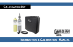
Advanced Calibration Designs, Inc.
Cal 2000
Gas Generator
Release VI
Advanced Calibration Designs, Inc.
2024 W. McMillan Street
Tucson, Arizona 85705 • U.S.A.
Telephone: (520) 290-2855 • Fax: (520) 290-2860
E-mail: [email protected]
Revision - 070620
INSTRUCTION MANUAL
www.goacd.com
IX.
Instruction Manual
SPECIFICATIONS
Chlorine (Cl2).............................................................0.5 - 50.0 ppm
Chlorine Micro-Cell (Cl2).............................................0.05 - 1.0 ppm
Hydrogen (H2)......................................................0.5 - 50.0 ppm
Hydrogen Cyanide (HCN) ................................0.5 - 50.0 ppm
Hydrogen Sulfide Micro-Cell(H2S)...................0.05 - 1.0 ppm
Hydrogen Sulfide (H2S)..........................................0.5 - 50.0 ppm
Chlorine Dioxide (ClO2).....................................0.5 - 5.0 ppm
(ppm is variable with flow rate, output given at 1/2 LPM)
Cal 2000
Gas Generator
TABLE OF CONTENTS
Air Flow Rate (with internal pump)........................0.2 to 1 LPM
Sample draw rate (with pump disabled).............0.1 to 5 LPM
Useful Cell Life.................................................................50 hours
Warm-up time (to 90%)................Approximately 5 minutes
L x W x H........................8.5 x 4.25 x 3.0” (21.6 x 10.8 x 7.6 cm)
Weight...................................................................3 lbs. (1360 g)
Operating Temperature.......................................0° C to 50° C
Relative Humidity (intermittent use).............................0 -100%
Accuracy.............................................................±10%
Repeatability...................................................±5%
Battery Power.........................................................4 alkaline “C”
Battery Life...............................................20-30 hours (@ .5 LPM)
CSA Certified Instrinsically Safe
Class I, Division 1, Groups A, B, C & D
European Standards approval for Zone 0
I.
General Description
Page 2
II.
Normal Operation: Diffusion Mode
Page 7
III.
Normal Operation: Sample Draw Mode
Page 12
IV.
Menu Options
Page 14
V.
Maintenance
Page 16
VI.
Troubleshooting
Page 17
VII.
Standard Warranty
Page 19
VIII.
Accessory Items / Parts List
Page 21
IX.
Instrument Specifications
Page 23
Manufactured by:
Advanced Calibration Designs, Inc.
2024 W. McMillan Street
Tucson, Arizona 85705 USA
Phone: 520 290 2855 - Fax: 520 290 2860
Int'l Phone: 001 520 290 2855 - Fax: 001 520 290 2860
email: [email protected]
website: www.goacd.com
Page 23
Para bajar la version del manual en Español visite:
http://www.goacd.com/acd/Download/Download.html
Vous pouvez télécharger une version française de ce manuel à:
http://www.goacd.com/acd/Download/Download.html
WARNING:
This instrument generates calibration gas for toxic
gas detectors. The instruction manual should be
read and understood prior to operation of the
instrument. Failure to operate the instrument
correctly can lead to improper calibrations.
This instrument conforms to the protection requirements of the EC
DIRECTIVE 89/336/EEC on Electromagnetic Compatibility (EMC),
in accordance with the provisions of Statutory Instrument 2372.
362-0600-00
AC Adaptor, 115 VAC, US style plug
7.5VDC, 300 mA
510-2000-00
Chlorine Cell, 50 hrs
510-2000-20
Chlorine Cell, 100 hrs
510-2000-05
Chlorine Micro-Cell, 50 hrs
510-2050-00
Hydrogen Sulfide Cell, 50 hrs
510-2050-05
Hydrogen Sulfide Micro-Cell, 50 hrs
510-2060-00
Chlorine Dioxide Cell, 50 hrs
510-2060-20
Chlorine Dioxide Cell, 100 hrs
510-2070-00
Hydrogen Cyanide Cell, 50 hrs
510-2090-00
Hydrogen Cell, 50 hrs
510-2090-20
Hydrogen Cell, 100 hrs
715-0403-0X
3 Foot Hose w/connector, low flow,
1/4" OD
715-0405-0X
5 Foot Hose w/connector, low flow,
1/4" OD
730-0615-00
Hard-body, Water Resistant, Padded
Carrying Case
910-0603-00
Instruction Manual
The following standards have been applied:
EN 50081-1
Emissions Standard (Residential Commercial and Light Industry)
EN 50082-1
Immunity Standard (Residential Commercial and Light Industry)
Page 22
VIII.
Accessory Items / Parts List
The following items are available as accessories for the Cal
2000:
P/N
Description
113-0402-00
Male Hose Barb Quick Connector, 1/8"
OD hose
150-0121-00
Charcoal Filter Element, one each
150-0131-00
Charcoal Filter Element, package
of 12
I.
GENERAL DESCRIPTION
The Cal 2000 is a battery-powered, portable electrochemical
gas generator designed to calibrate toxic gas sensors. Fast
warm-up time allows the instrument to be turned off between
remotely located sensors saving battery life and avoiding generation of unwanted gas. A built-in mass flow sensor provides
accurate flow control and the ability to measure externally provided sample draw flow rates. The Cal 2000 uses the following components to produce the calibration gas/air mixture:
Internal Micro Pump
180-0100-00
Empty Plastic Bottle with Pipette for
Electrolyte
193-0100-00
Electrolyte, Chlorine (50 ml bottle)
193-0101-01
Electrolyte, Chlorine Dioxide (1 Qty. Refill)
193-0101-05
Electrolyte, Chlorine Dioxide (5 Qty. Refill)
193-0101-10
Electrolyte, Chlorine Dioxide (10 Qty.
Refill)
193-0101-25
Electrolyte, Chlorine Dioxide (25 Qty.
Refill)
193-0105-00
Electrolyte, Hydrogen Sulfide (50 ml
bottle)
193-0107-00
Electrolyte, Hydrogen Cyanide (50 ml
bottle)
193-0109-00
Electrolyte, Hydrogen (50 ml bottle)
A small, rotary vane, micro air pump draws in ambient air to
blend with the generated gas. The pump may be disabled for
use in calibrating sample draw instruments.
Electrochemical Generating Cell
Page 21
The electrochemical generating cell contains an electrolyte
solution and either inert or consumable electrodes, depending upon the gas being generated. A precise concentration of
gas is produced when a known amount of current and a known
amount of air is supplied continuously to the cell. Each cell
has a built-in memory chip that tells the Cal 2000 instrument
what type and range of gas can be generated and how much
cell life is remaining. The electronics board mounted to the
cell should never be removed from the cell. Removal of this
board will void warranty and destroy the cell. Due to the design characterization of the cell, the unit must be oriented flat
(on the units feet) for correct concentration output.
Page 2
Cell Installation and Removal
There are no tools required by the end user for service of the instrument. The electrochemical cells
are shipped seperate of the unit and should be installed on receipt. To install the cell, remove the bottom
cover of the instrument. This is done by pulling each of the
‘plunger feet’ on the bottom of the instrument. Once all of
the plungers have been pulled out, the bottom cover is simply removed from the instrument.
warranty of fitness for a particular purpose. In no event
shall Advanced Calibration Designs, Inc. be liable for
direct, incidental or consequential loss or damage of any
kind connected with the use of its products or failure of its
products to function or operate properly.
The following is a listing of the available electrochemical
Cal 2000 cells and their standard prorated warranty when
installed in equipment manufactured and supplied by
Advanced Calibration Designs, Inc.
50 Hour Generating Cells
1.
2.
3.
4.
5.
Chlorine - One year or 50 hours of use.
Hydrogen Sulfide - One year or 50 hours of use.
Hydrogen Cyanide - One year or 50 hours of use .
Hydrogen - One year or 50 hours of use .
Chlorine Dioxide - One year, 50 hours of use .
100 Hour Generating Cells
The cell is keyed to ensure proper alignment into the instrument. When installed, the circuit board of the cell should
be flat with the bottom of the instrument. Push up on the
clear window at the back of the instrument to eject the cell.
Page 3
1.
2.
3.
4.
5.
Chlorine - One year or 100 hours of use.
Hydrogen Sulfide - One year or 100 hours of use.
Hydrogen Cyanide - One year or 100 hours of use .
Hydrogen - One year or 100 hours of use .
Chlorine Dioxide - One year, 100 hours of use .
Page 20
VII.
Standard Warranty
We warrant gas calibration equipment manufactured and
sold by us to be free from defects in materials, workmanship
and performance for a period of one year from date of
shipment. Any parts found defective within that period will
be repaired or replaced, at our option, free of charge, F.O.B.
factory. This warranty does not apply to those items which
by their nature are subject to deterioration or consumption in
normal service, and which must be cleaned, repaired, or
replaced on a routine basis.
Such items may include, but are not limited to:
a.
Electrochemical type generating cells
b.
Electrolyte
c.
Batteries
Warranty is voided by abuse including rough handling,
mechanical damage, alteration, or repair procedures not in
accordance with the instruction manual. This warranty
indicates the full extent of our liability, and we are not
responsible for removal or replacement cost, local repair
costs, transportation costs or contingent expenses incurred
without our prior approval.
Advanced Calibration Designs, Inc.'s obligation under this
warranty shall be limited to repairing or replacing, and
returning any product which shall be returned to Advanced
Calibration Designs, Inc. at its manufacturing facilities, with
transportation charges prepaid, and which Advanced
Calibration Designs, Inc.'s Material Review Board examination shall disclose to its satisfaction to have been defective.
This warranty is expressed in lieu of any and all other
warranties and representations, expressed or implied, and
all other obligations or liabilities on the part of Advanced
Calibration Designs, Inc. including, but not limited to, the
Page 19
Alkaline "C" Batteries
A set of four fully charged, heavy duty alkaline "C" batteries
provides 20-30 hours of operation at .5 LPM.
Note: Rechargeable or light duty batteries can be used, but they
give significantly less operating time.
Microprocessor-Based Circuitry
The Cal 2000 has microproccessor based circuitry that performs several different operations and offers the user many
different features. The microprocessor tracks cell and battery
usage, monitors the air flow rate and controls the cell and pump
to give the selected ppm and flow rate. In addition to English,
every Cal 2000 is capable of providing menu displays in French,
German and Spanish. See section IV. Menu Options for instructions on how to change the menu language.
Digital Display
The Cal 2000 has a liquid crystal display (LCD) located on the
front of the instrument. This display is protected by a thin,
clear plastic cover that is part of the front label and may be
replaced if it becomes scratched or unclear.
POWER and SELECT
The POWER and SELECT switches are momentary push button type switches activated through the front membrane panel.
They are physical switches mounted directly on the circuit
board.
Nylon Carrying Case
The Cal 2000 comes with a convenient, durable, nylon carrying case. It is adjustable to be worn as a hip pack, or the belt
strap can be reattached to be worn around the neck or over
the shoulder. The top of the carrying case is clear plastic,
allowing the unit to be operated while within the case, and
there is a convenient front pocket for storage of additional cells
or the delivery hose.
Page 4
Delivery Hose
"Cell Failure!"
The instrument comes standard with a three (3) foot long,
¼ inch diameter norprene hose for delivering the gas to the
sensor or calibration adapter. The hose has a male quick
connect adapter for easy attachment to the instrument.
accompanied by an audible beep.
There are two possible causes for a cell failure. One
cause is that the instrument has not detected a cell. The
other is that a high voltage has been detected across the
cell.
Mass Flow Sensor
The Cal 2000 has a built-in mass flow sensor that measures
the flow rate of the instrument. This information is used in two
ways. With the pump engaged, it is used to control the pump
to the desired flow rate over a range of 0.2 to 1.0 LPM. With
the pump disabled, it is used to measure the air flow rate drawn
through the Cal 2000 by an external pump. This information
is used to adjust the cell current to the desired ppm. The flow
meter should be calibrated against a primary mass flow standard every 12 to 24 months.
Internal Charcoal Filter
An internal charcoal filter is provided to scrub contaminated
air and provide a clean baseline for “zeroing” sensors. This
filter should be replaced on a yearly basis and is removed
by pulling out the grey plunger at the top of the unit. Spare
filter elements can be purchased through ACD. Note: The
charcoal filter must be fully installed into the instrument for
correct operation.
If the cell is not initially detected by the processor, the unit
will display cell failure and immediatly shut down (without
entering ‘purge mode’). This failure can happen either
because a cell is not inserted, connection to the cell is not
made, or due to a failure of the circuit board on the generating cell.
The cell failure alarm will also engage if the microprocessor detects an abnormally high cell voltage condition. One
possibility for this high voltage is that one of the pins may
be making a faulty electrical connection. Another possibility
is that the electrolyte level is too low. For instructions on
how to replenish the electrolyte refer to
Section V: Maintenance.
If this message continues after the cell has been plugged
in correctly and the electrolyte level has been confirmed to
be sufficient, contact the factory and/or replace the cell.
"Cell is used up! “
accompanied by an audible beep.
The cell life has expired and the display will show 0% cell
life remaining. Replace the cell.
"Battery is low!"
accompanied by an audible beep.
If battery power drops below 5% capacity, the screen will
flash "Battery is low!". Replace the batteries or switch to AC
power.
Page 5
Page 18
VI.
Troubleshooting
Optional items available for the Cal 2000 include:
No Power To Instrument
AC Adapter
There are two common causes for the unit to not power
up when the POWER switch is pressed for three seconds.
The Cal 2000 may also be operated from an AC adapter.
The AC adapter converts the AC voltage supplied from the
main power lines to 6 VDC which is used in lieu of the batteries. The adapter plugs into the instrument from the underside of the case directly into the power board and is independent of polarity. If needed, contact the factory for
exact specifications of the AC adapter.
The most common is that the batteries are dead. Try
replacing the batteries with new alkaline batteries or try
powering the unit from the AC power adapater.
The second most frequent cause for no power to the
instrument is a blown protective fuse. This fuse can be
shorted out if the batteries have been removed from
the instrument with a metallic object such as a
screwdriver. If the protective fuse has been blown
contact the factory.
"Flow too low" / "Flow too high"
Hard Body Instrument Case
A water resistant, padded instrument case is available for
storage and shipping of the Cal 2000. The case is made
out of rugged, high impact resistant plastic and will help protect the instrument in harsh environments. The foam insert
may be customized to hold additional items like spare batteries and cells.
accompanied by an
audible beep.
Extension Hoses
Accurate air flow is critical to an accurate gas mixture.
The microprocessor and built-in precision mass flow
sensor continuously monitor the air flow. If, however, a
flow problem develops (e.g. air blockage or kinked tubing)
which cannot be corrected within ten seconds, the unit will
display "Flow too low." If the problem cannot be cleared
after an additional minute, the instrument will enter the
purge mode and then power down.
Longer sample hoses may be purchased for use with the
Cal 2000 in lengths up to 20 feet. Note: the internal pump
may not be capable of overcomming flow restricions associated with extreme hose lengths when operating at 1.0 LPM.
If the pump was not disabled prior to attaching an external
pump device, or the sample draw flow rate is greater than
5.0 LPM, the unit will display "Flow too high." If the
problem is not cleared within one minute, the instrument
will enter purge mode as above.
Page 17
Page 6
II.
Normal Operation: Diffusion Mode
To start the generator, press and hold the POWER switch,
located in the middle left front of the instrument, until the
display reads A. C. D., approximately three (3) seconds.
Release the switch immediately thereafter.
The instrument will sequence through several screens as
follows:
A. C. D. VI
Copyright 2000
Please Note: If you would like to change the language of
the menus, see section IV. Menu Options: Foreign
Language Option, for instructions.
The instrument will display the Serial Number and Cell
Number, followed by the manufactured date.
Serial # 0000001
Cell # 000001
V.
Maintenance
The electrochemical cells of the CAL 2000 require periodic
maintenance to provide optimum performance. It is
recomended that the electrolyte solution be replaced on an
annual basis for most gases generated by the CAL 2000.
The exception to this is the ClO2 electrolyte. Please refer to
the instructions enclosed with every chlorine dioxide cell or
replacement electrolyte pack.
If the instrument is returned with the cell on an annual basis
to maintain NIST certification, the electrolyte will be replaced
by the factory.
The following steps should be taken to replace electrolyte.
........a. Remove cell as described in section I. General
Description: Cell Installation and Removal.
........b. Unscrew solid fill plugs on reservoir and
remove liquid.
........c. Use syringe (provided with electrolyte) to add
liquid to within 1/8 inch from the bottom of fill hole.
Warning: Do not over-fill reservoir. Trapped air must be
allowed to escape through vent plug as fill screw is
replaced. Contact the factory for more information.
........d. Replace fill plugs.
Caution
Manufactured
01 Jan 2000
Calibration Date
01 Jan 2000
Page 7
Both the electrochemical cell and the alkaline batteries used
in the CAL 2000 instrument contain corrosive chemicals. In
addition, depending on the type of cell being used, the gas
being generated can be corrosive. The design of the
instrument takes this into consideration, and the 300
second purge cycle allows the corrosive gases to be swept
out of the instrument. It is important not to remove the
generating cell before this purge cycle is completed. While it
is not expected that the chemicals in the cell or alkaline
batteries will leak during normal operation, it is recommended that both the generating cell and the alkaline
batteries be removed from the instrument if it is being stored
for periods longer than one week between use.
Page 16
H2S Quick Select Option
After the Battery Status screen appears during the start up of
the instrument, if a H2S cell is in the instrument, a message
will appear offering the option of changing to Quick Select
mode.
Quick Select Off
Select To Change
The following status screens indicate the remaining cell life
and battery status.
Cell Life
049 Hrs 59 Mns
You can switch to the quick select mode by pressing the
SELECT switch. If you do you will enter the Quick Select
choice screen.
Quick Select Off
No
The Calibration Date refers to when the instrument itself
was last calibrated at the Factory. It does not refer to the
calibration date of the generating cells, which are field
replaceable.
Battery Status
100% remaining
Yes
You can turn the Quick Select mode off by pressing the
POWER switch (arrow up) or you can turn it on by pressing
the SELECT switch (arrow down).
At any time during the operation of the unit or during the stabilization period you can enter the menu to change the Quick
Select mode by pressing the SELECT switch (arrow down).
It is important to note that when you enter the Quick Select
mode for the H2S cell, you cannot change the flow rate of the
instrument. The Cal 2000 instrument will automatically vary
the flow rate to acheive the different ppm concentrations of
H2S.
Once you have entered the Quick Select mode for the Cal
2000, you can only adjust the ppm concentration in fixed 10
ppm increments, between 20 ppm and 100 ppm.
Page 15
Please Note: If you have a ClO2 or H2S cell in the unit you
will recieve an additional message at this time. Please
refer to section IV. Menu Options for additional information.
When the air flow rate screen appears,
Flow: 0.5 lpm
SELECT to change
you may adjust your flow rate by pressing the SELECT
switch. If you do, you will enter the flow adjust screen.
0.2 to 1.0 lpm
set . . . 0.0 lpm
Page 8
You may adjust the flow upwards by pressing the POWER
switch (arrow up) or downwards by pressing the SELECT
switch (arrow down). If you set the flow to 0.0 LPM, the
instrument will disable the pump and enter the flow draw
mode. Please refer to section III. Normal Operation:
Sample Draw Mode for more information. If you set the
flow between 0.2 and 1.0 LPM, the instrument will automatically adjust the pump to the requested flow rate using
feedback from the built-in mass flow sensor.
Immediately after the flow rate screen appears, the ppm
screen appears.
Output: 000 ppm
SELECT to change
You may change the ppm by pressing the SELECT switch.
10 to 50 ppm
set . . . 000 ppm
You may adjust the ppm upwards by pressing the POWER
switch (arrow up) or downwards by pressing the SELECT
switch (arrow down). If you set the ppm to 000 ppm, the
instrument will not generate any gas, although it will
continue to pump.
The minimum and maximum ppm settings are dependent
upon the flow rate and the type of generating cell installed in
the instrument. The Cal 2000 will read the memory chip
inside the generating cell and automatically display the
minimum and maximum ppm available for the flow rate that
the instrument is set to. The total range of the cell is divided
into three sub ranges to allow for appropriate resolution in
each sub range. For all cells (excepting CLO2 and the
Micro-cells) the sub ranges at .5 LPM are .5 to 1 PPM,
Page 9
IV.
Menu Options
Foreign Language Option
The menu options can be adjusted to read in German,
French, or Spanish. To change the language, start the unit as
you normally would. When the ACD screen appears,
A. C. D. VI
Copyright 2000
press the SELECT button. This will bring up the following
screen:
English
SELECT to change
Press the SELECT button to choose the preferred language.
When the language is displayed, press the POWER button to
continue with the start up sequence.
ClO2 Cell Reminder Screen
After the Battery Status screen appears during the start up of
the instrument, if a ClO2 cell is in the instrument, a reminder
message will appear to change the Chlorine Dioxide Electrolyte.
Electrolyte Exp.
Renew Often
Please read section VI. Cell Maintenance for detailed information on changing your electrochemical generating cell’s
electrolyte.
Page 14
Once the instrument has achieved a stable flow rate, it will
alternate between the ppm, air flow rate and stabilization
screen as described previously. At this point, you may press
SELECT to go to the status screens and adjust the ppm as
described earlier. If the flow rate changes significantly
during this period, the instrument will attempt to re-stabilize
at the new flow rate. The instrument operates identically to
the diffusion mode at this point.
WARNING: Do not adjust the flow rate to more than 0.0
LPM while the Cal 2000 is attached to a sample draw
unit or damage may occur to the instrument. Also, do
not attach the Cal 2000 to pumps drawing more than 5
LPM.
1.0 to 10.0 PPM and 10 to 50 PPM. When the end of a given
range is reached, pressing the appropriate up or down
arrow will automatically toggle the display to the next
appropriate range. Note that to obtain higher concentrations of gas simply reduce the flow rate of the instrument.
Once the flow and concentration have been set, the
instrument will enter the stabilization period and the display
will alternate between the following three screens:
Stabilizing ...
Standby: 146 sec
1.00 ppm CL2
Standby: 145 sec
Flow: 0.5 lpm
Standby: 144 sec
When the instrument has finished counting down to zero
(0) seconds, it has reached 90% of its final output and will
enter the gas generating mode. In this mode, the instrument will display the gas being generated, the flow rate, the
ppm setting and the time while running at these settings as
follows:
CL2 @ 0.5 lpm
1.0 ppm 00:00:00
Page 13
Page 10
At any time you may reset either the flow rate or the ppm rate
by pressing the SELECT button and entering the status
screens as described above.
When you are finished generating gas and wish to turn off
the instrument, press and hold the POWER switch until the
purge screen is displayed.
]
Purging ...
Standby: 300 sec
The instrument will purge itself of gas for 300 seconds and
then automatically shut off. At any time during this period,
you may turn the instrument back on by pressing the
SELECT switch and entering the status screens as described
above. You must change either the flow rate or the ppm
setting and then the instrument will immediately go to the
stabilization screen and continue to run at the new settings.
The amount of stabilization time will depend upon how long
the instrument was in the purge mode.
III. Normal Operation: Sample Draw Mode
The instrument may also be operated in a sample draw
mode where the internal pump is disabled and the air is
drawn through the instrument by an external pump. This
mode is used for calibrating sample draw instruments.
To enter the sample draw mode, press the SELECT switch
when the flow status screen is displayed.
Flow: 0.5 lpm
SELECT to change
When the flow set screen appears, adjust the flow to read
0.0 LPM.
0.2 to 1.0 lpm
set . . . 0.0 lpm
The ppm output screen will then read 000 ppm. You will be
unable to set the ppm until the sample draw instrument has
been attached to the outlet hose and a stable flow rate has
been established. While the instrument is waiting for the
sample draw unit to be attached, it will display the flow
stabilization screen.
Stabilize flow..
Flow: 0.000 lpm
Page 11
Page 12