1
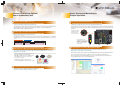
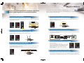
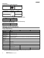
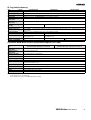
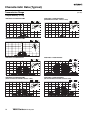
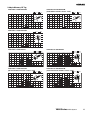
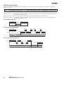
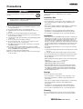
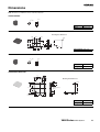
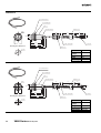
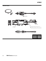
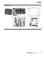
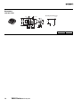
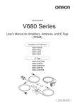
NEW
RFID System
V680 Series
Next-Generation RFID System
Conforming to ISO 18000-3 (ISO 15693)
Visualize data
transmission on
production lines.
Managing process instructions
and histories for engine
manufacturing
Managing manufacturing process
traceability
Read/Write
Antenna
Read/Write
Antenna
Managing the manufacture of LCDs
and color filters
Managing dies, die histories,
and die service lives
Read/Write
Antenna
Read/Write
Antenna
Diverse Functions for Optimal
Use on Production Lines
Easier Startup and Maintenance.
Simpler Operation.
Conforms to ISO 18000-3 (ISO 15693)
Lets You Visualize Data Transmission
Can be used in many countries around the world.
Contributes to higher efficiency for on-site startup and maintenance.
The V680 Series meets the requirements of the radio wave regulations of Japan, Europe, and North America.
(Approval applications have also been filed in various other countries. Contact your OMRON sales
representative for details on applicable countries.)
Seven maintenance modes make it easy to diagnose the optimal usage conditions for the V680 RFID System.
Startup is also easier because the system can be checked without having to use a personal computer or other
host device.
Maintenance modes are
quickly switched with
the DIP switch on the
front of the Controller.
Enables High-speed Data Transmission
High-speed transmission of 27 kbps achieved.
The V680 Series offers data transmission speeds as high as 27 kbps at an operating frequency of 13.56 MHz,
and dramatically shortens turn around time (TAT) with a Self-execution Mode that eliminates the need for host
access.
Self-execution system
ID Tag
transmission time
Judgment and
instruction
Conventional system
Host send (response)
judgment and instruction time
Host send (command) time
Judgment and
instruction
ID Tag
transmission time
TAT
TAT
A Wide Range of ID Tags Available for Various Production Lines
These ultra-compact Tags also feature high environmental durability, long service lives,
and battery-less operation.
Strong Support for Creating ID Tag Memory Maps
Using the ID Map Manager dramatically shortens the time required to allocate
ID Tag memory and complete system designs.
Work efficiency is greatly increased because the ID Map Manager includes an ID Tag read/write test function
and communications checking function in addition to memory map definition and editing functions.
Memory map data created by the ID Map Manager can also be easily shared between the production line
design department and the vendors that are building the line.
The same ID Tag model can be either embedded in
metal or mounted on non-metallic objects.
Embedding in metal requires no extra attachments.
The 2-Kbyte memory has a long service life of
10,000,000,000 accesses.
The V680 Series features the same level of
environmental durability as the previous V600 Series.
The Amplifier Unit is also
equipped with an indicator that
displays the communications
condition, for easy confirmation
from the location nearest the
production line.
10
billion
accesses
Long service life
Battery-less
No Changes Needed when Switching from an Existing System
The V680 Series also supports V600-series commands,
so there is no need to change command systems.
V680-A-IMMEG-P01
Visualize Data Transmission without the Need for a Host Device.
Perform Simple Diagnosis of Communications Conditions.
Seven maintenance modes make it easy to diagnose the communications conditions from the front
panel of the Controller or Amplifier Unit. The data can also be output from the USB port of the Controller
to a personal computer or other monitoring device.
Distance Level Measurement Mode
Communications Success Rate Measurement Mode
Confirms correct mounting positions for the Read/Write Antenna and ID Tag.
Confirms the communications success rate between the Read/Write Antenna and ID Tags.
The distance between the Read/Write Antenna and ID Tag mounting locations relative to the communications
range is displayed using six levels.
A total of 100 communications are executed without retries, and the rate of communications success is
displayed in levels ranging from 01 to 99.
Distance level “--”
Controller
Amplifier Unit
ID Tag
Controller
“01”
ID Tag
“02”
“03”
“04”
100
communications
“05”
“06”
Read/Write
Antenna
Read/Write
Antenna
Distant
Communications successes: 23
Close
Host Device Communications Monitor Mode (Protocol Analyzer Function)
Noise Level Measurement Mode
This mode can be used as a protocol analyzer function for host device communications lines.
Confirms spatial noise, noise sources, and noise countermeasure effects.
The communications commands sent from the host device and the execution result responses can be output
from the USB port of the Controller.
Measures the ambient noise level and displays it in levels ranging from 00 to 99.
Monitor
Host device
Controller
Command:
RDSTH100100010*CR
Monitor:
RDSTH100100010*CR
RD72*CR
Read/Write
Antenna
Personal computer
Read/Write
Antenna
Little noise
Programmable Controller
(PLC)
Notebook PC
Response:
RD72*CR
Tag Communications Test Mode
Much noise
Confirms communications ability between the Read/Write
Antenna and ID Tags.
Speed Level Measurement Mode (Read/Write)
Confirms the speed of moving ID Tags and the number of usable bytes.
Data is transmitted repeatedly to moving ID Tags, and the number of successful communications and speed
level are displayed in levels ranging from 01 to 99.
(No data is actually written to the ID Tags during the write part of the Speed Level Measurement Mode.)
Controller
The end codes are displayed to show the results of communications
between the Read/Write Antenna and ID Tags. When the Controller
is mounted inside a control panel, or in some other location, this
data can be output from the Controller's USB port and easily
checked on a monitor.
(The Tag Communications Test Mode uses only read operations.)
Controller
Normal communication
Communications error
Movement
ID Tag
Host Device Communications Confirmation Mode
Confirms whether the signals sent from the Controller are being correctly transferred to an external device.
Read/Write
Antenna
More than 99 successful
communications
The communications commands and responses between the Controller and a host device are output from the
Controller's USB port for easy identification of problems, such as incorrect communications parameters or wiring.
RFID System
V680 Series
New, Next-generation
RFID Systems with ISO 18000-3
(ISO15693) Compliance
• High-speed, 27-kbps transmission.
• Wide line-up of ultra-compact size, long-life, 2-Kbyte
ID Tags. (New 1-Kbyte ID Tags available soon.)
• Seven modes make it possible to visualize data
transmission.
• ID Map Manager simplifies memory map designing
for ID Tags.
• Complies with FCC Standards and R&TTE Directive.
System Configuration
ID Tag
1-Kbyte memory
V680-D1KP52MT
(8 dia. × 5 mm)
For embedding in
metallic or nonmetallic surface
Read/Write Antenna
Cylinder type
V680-HS52
Amplifier Unit
Controller
V680-HA63A
1-channel type
V680-CA5D01
Available
soon.
V680-D1KP66MT
(34 × 34 × 3.5 mm)
For flush mounting
on metallic surface
Personal
computer
Available
soon.
V680-D1KP66T
(34 × 34 × 3.5 mm)
For flush mounting on
non-metallic surface
Programmable
Controller
Available
soon.
2-Kbyte memory
V680-D2KF52M
(8 dia. × 5 mm)
For embedding in
metallic or nonmetallic surface
Square type
V680-HS63
V680-D2KF67M
(40 × 40 × 4.5 mm)
For flush mounting
on metallic surface
V680-D2KF67
(40 × 40 × 4.5 mm)
For flush mounting on
non-metallic surface
6
-W: Standard cable,
waterproof
connector
-R: Flexible cable,
non-waterproof
connector
V680 Series RFID System
V680-HA63B
2-channel type
V680-CA5D02
Ordering Information
ID Tag
Type
Battery-less
Memory capacity
Appearance
1 Kbyte
2 Kbytes
Size
Metallic compatibility
Model
Cylindrical, ultracompact
8 dia. × 5 mm
For embedding in metallic V680-D1KP52MT
or non-metallic surface
Available soon.
Square
34 × 34 × 3.5 mm
For flush mounting on
metallic surface
V680-D1KP66MT
For flush mounting on
non-metallic surface
V680-D1KP66T
Available soon.
Available soon.
Cylindrical, ultracompact
8 dia. × 5 mm
For embedding in metallic V680-D2KF52M
or non-metallic surface
Square
40 × 40 × 4.5 mm
For flush mounting on
metallic surface
V680-D2KF67M
For flush mounting on
non-metallic surface
V680-D2KF67
Read/Write Antenna (Detachable Amplifier Unit Type)
Type
Cylindrical
Appearance
Size
M22 × 65 mm
Standard cable,
waterproof connector
Flexible cable, nonwaterproof connector
Square
40 × 53 × 23 mm
Standard cable,
waterproof connector
Flexible cable, nonwaterproof connector
Cable length
Model
2m
V680-HS52-W 2M
12.5 m
V680-HS52-W 12.5M
2m
V680-HS52-R 2M
12.5 m
V680-HS52-R 12.5M
2m
V680-HS63-W 2M
12.5 m
V680-HS63-W 12.5M
2m
V680-HS63-R 2M
12.5 m
V680-HS63-R 12.5M
Amplifier Unit
Type
Appearance
Size
25 × 40 × 65 mm
For 1-Kbyte memory
For 2-Kbyte memory
Cable length
Model
5m
V680-HA63A 5M
10 m
V680-HA63A 10M
5m
V680-HA63B 5M
10 m
V680-HA63B 10M
Controller
Type
DC power supply
No. of connectable
Amplifiers
Single
Dual
Appearance
Size
105 × 90 × 65 mm
Transmission interface
RS232C,
RS422/RS485
Model
V680-CA5D01
V680-CA5D02
V680 Series RFID System
7
Accessories
ID Tag Attachment (Order Separately)
Type
Appearance
For the V680-D1KP66T
Model
V600-A86
Amplifier Unit Extension Cable (Order Separately)
Cable length
Appearance
Model
10 m
V700-A43 10 M
20 m
V700-A44 20 M
RS-232C Communications Connector (Order Separately)
Name
Model
Connector Plug
XM3B-0922-111
Connector Hood
XM2S-0911
RS-422/RS-485 Communications Connector (Accessory)
Setting Tool (ID Map Manager)
Type
Model
English version
V680-A-IMMEG-P01
Ratings and Performance
ID Tag (1-Kbyte Memory)
Item
Model
V680-D1KP52MT
V680-D1KP66T
Memory capacity
1 Kbyte (user area)
Memory type
EEPROM
Data storage time
10 years (after the data is written)
Memory life
Number of accesses: 100,000 times per address (at 25°C)
Ambient operating
temperature (during
transmission)
−25 to 85°C (with no icing)
Ambient operating
temperature (not during
transmission)
V680-D1KP66MT
−40 to 125°C (with no icing)
Heat resistance: 1,000 thermal cycles each of 30 minutes at −10°C/150°C, High-temperature storage: 1,000 hours
at 150°C (See Note 1.)
Ambient storage
temperature
−40 to 125°C (with no icing)
Ambient operating
humidity
35 to 95%
Degree of protection
IEC 60529, IP68
IP67G (JEM)
Vibration resistance
10 to 2,000 Hz, 1.5-mm double amplitude at 150 m/s2 acceleration with 10 sweeps in X, Y, and Z directions for 15
minutes each
Shock resistance
500 m/s2 in X, Y, and Z directions 3 times each (18 times in total)
Appearance
8 dia. × 5 mm
34 × 34 × 3.5 mm
Materials
Case: PPS resin
Molding: PPS resin
Filling: Epoxy resin
Weight
Approx. 0.5 g
Approx. 6 g
Approx. 7.5 g
Metallic compatibility
Yes
No
Yes
Note 1. 150°C heat resistance: The heat resistance has been checked at 150°C for up to 1,000 hours, and thermal shock has been checked
through testing 1,000 thermal cycles each of 30 minutes at −10/150°C. (Test samples: 22, defects: 0)
2. For details, refer to the User's Manual (Cat. No. Z248).
8
V680 Series RFID System
ID Tag (2-Kbyte Memory)
Item
V680-D2KF52M
Model
V680-D2KF67
V680-D1KF67M
Memory capacity
2 Kbytes
Memory type
FRAM
Data storage time
10 years (at 55°C max.)
Memory life
Number of accesses: 10,000,000,000 times per address (at 85°C)
Ambient operating
temperature
−25 to 85°C (with no icing)
Ambient storage
temperature
−40 to 85°C (with no icing)
Ambient operating
humidity
35 to 95%
Degree of protection
IP67 (JEM)
Vibration resistance
10 to 2,000 Hz, 1.5-mm double amplitude at 150 m/s2 acceleration with 10 sweeps in X, Y, and Z directions for 15
minutes each
Shock resistance
500 m/s2 in X, Y, and Z directions 3 times each (18 times in total)
Appearance
8 dia. × 5 mm
40 × 40 × 4.5 mm
Materials
Case: PPS resin
Filling: Epoxy resin
Molding: ABS resin
Filling: Epoxy resin
Weight
Approx. 0.5 g
Approx. 6.5 g
Approx. 7 g
Metallic compatibility
Yes
No
Yes
35 to 85%
Cylindrical Read/Write Antenna (Detachable Amplifier Unit Type)
Model
Item
V680-HS52-W
(Standard Cable, Waterproof Connector)
V680-HS52-R
(Flexible Cable, Non-waterproof Connector)
Ambient operating
temperature
−10 to 60°C (with no icing)
Ambient storage
temperature
−25 to 75°C (with no icing)
Ambient operating
humidity
35% to 95% (with no condensation)
Insulation resistance
20 MΩ min. (at 500 VDC) between the cable terminals and the case
Dielectric strength
1,000 VAC (50/60 Hz) for 1 minute between the cable terminals and the case with a current leakage of 5 mA max.
Degree of protection
IP67G (Sensor Head) (See note 1.)
Vibration resistance
10 to 500 Hz variable vibration, 1.5-mm double amplitude at 100 m/s2 acceleration, with 10 sweeps in X, Y, and Z
directions for 8 minutes each
Shock resistance
500 m/s2 in X, Y, and Z directions 3 times each (18 times in total)
Appearance
M22 × 65 mm
Materials
ABS, brass, epoxy resin filling
Weight
Approx. 850 g (with 12.5-m cable)
Cable length
2 m, 12.5 m
IP67G (Sensor Head) (See note 2.)
Note 1. The degree of protection for the Connector is IP67/IP65.
2. The Connector is not waterproof.
3. For details, refer to the User's Manual (Cat. No. Z248).
V680 Series RFID System
9
Square Read/Write Antenna (Detachable Amplifier Unit Type)
Model
Item
V680-HS63-W
(Standard Cable, Waterproof Connector)
V680-HS63-R
(Flexible Cable, Non-waterproof Connector)
Ambient operating
temperature
−10 to 60°C (with no icing)
Ambient storage
temperature
−25 to 75°C (with no icing)
Ambient operating
humidity
35% to 95% (with no condensation)
Insulation resistance
20 MΩ min. (at 500 VDC) between the cable terminals and the case
Dielectric strength
1,000 VAC (50/60 Hz) for 1 minute between the cable terminals and the case with a current leakage of 5 mA max.
Degree of protection
IP67G (Sensor Head) (See note 1.)
Vibration resistance
10 to 500 Hz variable vibration, 1.5-mm double amplitude at 100 m/s2 acceleration, with 10 sweeps in X, Y, and Z
directions for 11 minutes each
Shock resistance
500 m/s2 in X, Y, and Z directions 3 times each (18 times in total)
Appearance
40 × 53 × 23 mm
Materials
ABS, epoxy resin filling
Weight
Approx. 850 g (with 12.5-m cable)
Cable length
2 m, 12.5 m
IP67G (Sensor Head) (See note 2.)
Note 1. The degree of protection for the Connector is IP67/IP65.
2. The Connector is not waterproof.
3. For details, refer to the User's Manual (Cat. No. Z248).
Amplifier Unit
Item
V680-HA63A
Model
V680-HA63B
Ambient operating
temperature
−10 to 55°C (with no icing)
Ambient storage
temperature
−25 to 65°C (with no icing)
Ambient operating
humidity
35% to 85% (with no condensation)
Insulation resistance
20 MΩ min. (at 500 VDC) between the cable terminals and the case
Dielectric strength
1,000 VAC (50/60 Hz) for 1 minute between the cable terminals and the case with a current leakage of 5 mA max.
Degree of protection
IP40 (IEC60529) See note 1.
Vibration resistance
10 to 500 Hz variable vibration, 1.5-mm double amplitude at 100 m/s2 acceleration, with 10 sweeps in X, Y, and Z
directions for 11 minutes each
IP67/IP65 (IEC60529) See note 2.
Shock resistance
500 m/s2 in X, Y, and Z directions 3 times each (18 times in total)
Appearance
25 × 40 × 65 mm (not including projections)
Material
Polycarbonate (PC) resin
Weight
Approx. 650 g (with 10-m cable)
Cable length
5 m, 10 m (See note 3.)
Transmittable ID Tags
1-Kbyte memory
2-Kbyte memory
Note 1. When connected to the V680-HS63-R or V680-HS52-R.
2. When connected to the V680-HS63-W or V680-HS52-W. (Not including the Connector on the Controller.)
3. The maximum extendable cable length is 50 m (including the Amplifier Unit Cable). The maximum number of cables that can be connected
is two.
4. For details, refer to the User's Manual (Cat. No. Z248).
10
V680 Series RFID System
Controller
Item
Model
V680-CA5D01
Power supply voltage
Power consumption
24 VDC (−15% to +10%)
15 W max., 0.8 A max.
Ambient operating
temperature
−10 to 55°C (with no icing)
Ambient operating
humidity
25% to 85% (with no condensation)
Ambient storage
temperature
−25 to 65°C (with no icing)
V680-CA5D02
Ambient storage humidity 25% to 85% (with no condensation)
Insulation resistance
20 MΩ min. (at 500 VDC) applied as follows:
(1) Between power supply terminals and grounded case
(2) Between ground and terminals
Dielectric strength
1,000 VAC (50/60 Hz) for 1 minute
(1) Between power supply terminals and grounded case
(2) Between ground and terminals
Degree of protection
Panel mounted (equivalent to IP20)
Vibration resistance
10 to 150 Hz variable vibration, 0.2-mm double amplitude at 15 m/s2 acceleration, with 10 sweeps in X, Y, and Z
directions for 8 minutes each
Shock resistance
150 m/s2
Appearance
105 × 90 × 65 mm (not including projections)
Material
Polycarbonate (PC) resin, ABS resin
Weight
Approx. 300 g
Mounting method
DIN Track or M4 screws
Connectable Amplifier
Units
1
2
Note: For details, refer to the User's Manual (Cat. No. Z249).
Transmission Specifications
Item
Specifications
RS-232C
RS-422/RS-485
Connector specifications 9-pin D-Sub connector with threaded socket: M2.6
5-pin connector mfd. by Phoenix Contact:
MC1.5/5GF-3.5
Transmission method
Half-duplex serial
4-wire/2-wire half-duplex serial
Transmission speed
9,600/19,200/38,400/115,200 bps
Data length
7 or 8 bits
Stop bit length
1 or 2 bits
Error detection
Parity (even/odd/none)
Cable length
15 m max.
500 m max.
■ Input/Output Specifications
Input Specifications
(RST, TRG1, TRG2)
Input voltage
24 VDC (+10% to −15%, including ripple)
(PNP and NPN compatible)
Input impedance
2.2 kΩ
Input current
ON voltage
OFF voltage
Input response
Output Specifications
(RUN, BUSY, OUT3, ERROR, OUT4, OUT1,
OUT2)
10 mA TYP (24 VDC)
Maximum
switching
capacity
24 VDC (+10% to −15%, including ripple)
100-mA photoMOS output (PNP and NPN
compatible)
19 V min.
Leakage current
100 µA max.
5 V max.
Residual voltage
2.0 V max.
70 ms max.
Note 1. When RST input is ON, the CPU halts operation and the RST
LED lights. The ERROR output is then reset.
2. Short-circuiting in a no-load condition may cause transistor
damage.
■ USB Port
The USB port is used for a simple connection with a personal computer using a USB cable. The port complies with USB 1.1, and the USB cable
uses a series A or series mini-B connector. A USB port driver must be separately provided. Consult with your OMRON representative for details.
When connected to a host device via USB, the communications will use 1:1 protocol regardless of the setting of DIP switches 3 to 9.
The USB port is not used for control purposes. When building a system, be sure to provide an RS-232C port or RS-422/ RS-485C port.
V680 Series RFID System
11
■ Performance Specifications
ID Tag (1-kbyte Memory) Transmission
Recommended combination
ID Tag
V680-D1KP52MT
Function
Read/Write Antenna
V680-HS52
Transmission
distance
(unit: mm)
Read
distance
0 to 9.0 mm
(axial deviation
±2)
Write
distance
0 to 8.5 mm
(axial deviation
±2)
ID Tag and Read/Write Antenna mounting conditions
V680-D1KP52MT
V680-HS52
V680-D1KP52MT
(embedded in metallic
surface: steel)
V680-HS52
Read
distance
Non-metallic
Non-metallic
(Resin, plastic, wood, etc.)
0 to 4.5 mm
(axial deviation
±2)
Iron
V680-HS52
Write
distance
V680-D1KP52MT
V680-HS63
0 to 4.0 mm
(axial deviation
±2)
Read
distance
0 to 12.0 mm
(axial deviation
±2)
Write
distance
0 to 9.5 mm
(axial deviation
±2)
Read
distance
0 to 17.0 mm
(axial deviation
±2)
Write
distance
0 to 17.0 mm
(axial deviation
±2)
V680-D1KP52MT
Non-metallic
V680-HS63
Non-metallic
(Resin, plastic, wood, etc.)
V680D1KP52MT
Non-metallic
V680-D1KP66T
V680-HS52
V680-D1KP66T
V680-HS52
V680-HS63
Read
distance
0 to 30.0 mm
(axial deviation
±10)
Write
distance
0 to 25.0 mm
(axial deviation
±10)
Read
distance
0 to 16.0 mm
(axial deviation
±2)
Write
distance
0 to 14.0 mm
(axial deviation
±2)
Non-metallic
(Resin, plastic, wood, etc.)
Non-metallic
V680-HS63
Non-metallic
(Resin, plastic, wood, etc.)
V680D1KP66T
Non-metallic
V680-D1KP66MT
(flush-mounted on
metallic surface: steel)
V680-HS52
V680-D1KP66MT
V680-HS52
Non-metallic
V680-HS63
Read
distance
0 to 25.0 mm
(axial deviation
±10)
Write
distance
0 to 20.0 mm
(axial deviation
±10)
V680-HS63
Iron
V680D1KP66MT
Non-metallic
12
V680 Series RFID System
Iron
ID Tag (2-kbyte Memory) Transmission
Recommended combination
ID Tag
V680-D2KF52M
Function
Read/Write Antenna
V680-HS52
Transmission
distance
(unit: mm)
Read
distance
0 to 8.0 mm
(axial deviation
±2)
Write
distance
0 to 8.0 mm
(axial deviation
±2)
ID Tag and Read/Write Antenna mounting conditions
V680-D2KF52M
V680-HS52
V680-D2KF52M
(embedded in metallic
surface: steel)
V680-HS52
Read
distance
Non-metallic
Non-metallic
(Resin, plastic, wood, etc.)
0 to 3.0 mm
(axial deviation
±2)
Iron
V680-HS52
Write
distance
V680-D2KF52M
V680-HS63
0 to 3.0 mm
(axial deviation
±2)
Read
distance
0 to 9.5 mm
(axial deviation
±2)
Write
distance
0 to 9.5 mm
(axial deviation
±2)
Read
distance
0 to 17.0 mm
(axial deviation
±2)
Write
distance
0 to 17.0 mm
(axial deviation
±2)
V680-D2KF52M
Non-metallic
V680-HS63
Non-metallic
(Resin, plastic, wood, etc.)
V680D2KF52M
Non-metallic
V680-D2KF67
V680-HS52
V680-D2KF67
V680-HS52
V680-HS63
Read
distance
7 to 30.0 mm
(axial deviation
±10)
Write
distance
7 to 30.0 mm
(axial deviation
±10)
Read
distance
0 to 16.0 mm
(axial deviation
±2)
Write
distance
0 to 16.0 mm
(axial deviation
±2)
Non-metallic
(Resin, plastic, wood, etc.)
Non-metallic
V680-HS63
Non-metallic
(Resin, plastic, wood, etc.)
V680D2KF67
Non-metallic
V680-D2KF67M (flush- V680-HS52
mounted on metallic
surface: steel)
V680-D2KF67M
V680-HS52
Non-metallic
V680-HS63
Read
distance
6 to 25.0 mm
(axial deviation
±10)
Write
distance
6 to 25.0 mm
(axial deviation
±10)
Iron
V680-HS63
Iron
V680D2KF67M
Non-metallic
V680 Series RFID System
13
Characteristic Data (Typical)
Transmission Range
(unit: mm)
1-kbyte Memory ID Tag
V680-HS52 & V680-D1KP52MT
V680-HS52 & V680-D1KP52MT
(embedded in metallic surface: steel)
Y
Y
50
40
X
30
−40
−30
−20
20
10
10
0
10
20
X
30
20
−10
Y
50
40
−50
Write
Read
Write
Read
Y
30
40
X
−50
−40
−30
−20
−10
0
10
20
30
40
X
V680-HS63 & V680-D1KP52MT
Write
Read
Y
Y
50
40
X
30
20
10
−50
−40
−30
−20
−10
0
10
20
30
40
X
V680-HS52 & V680-D1KP66T
V680-HS63 & V680-D1KP66T
Write
Read
Y
Y
50
40
X
30
−40
−30
−20
20
10
10
0
10
20
30
40
X
V680-HS52 & V680-D1KP66MT
(flush-mounted on metallic surface: steel)
−50
−40
−30
−20
−10
Y
14
40
X
Write
Y
50
40
X
30
−10
30
Read
40
−20
20
Y
50
−30
10
Write
Read
−40
0
V680-HS63 & V680-D1KP66MT
(flush-mounted on metallic surface: steel)
Y
−50
X
30
20
−10
Y
50
40
−50
Write
Read
Y
20
20
10
10
0
10
20
30
V680 Series RFID System
X
30
40
X
−50
−40
−30
−20
−10
0
10
20
30
40
X
2-kbyte Memory ID Tag
V680-HS52 & V680-D2KF52M
V680-HS52 & V680-D2KF52M
(embedded in metallic surface: steel)
Write
Read
Y
60
60
Y
50
−60
−50
−40
−30
−20
Y
50
40
−70
Write
Read
Y
40
X
30
30
20
20
10
10
−10
0
10
20
30
40
50
60
X
−70
−60
−50
−40
−30
−20
−10
X
0
10
20
30
40
50
60
X
V680-HS63 & V680-D2KF52M
Write
Read
Y
60
Y
50
40
X
30
20
10
−70
−60
−50
−40 −30
−20
−10
0
10
20
30
40
50
60
X
V680-HS52 & V680-D2KF67
V680-HS63 & V680-D2KF67
Read
Write
60
50
40
40
X
−50
−40
−30 −20
20
20
10
10
−10
0
10
20
30
40
50
60
X
V680-HS52 & V680-D2KF67M
(flush-mounted on metallic surface: steel)
−70 −60 −50
−40
−30
−20
−10
10
20
30
40
50
60
X
Write
Read
Write
Read
Y
60
Y
60
Y
50
50
40
40
X
30
−10
0
V680-HS63 & V680-D2KF67M
(flush-mounted on metallic surface: steel)
Y
−70 −60 −50 −40 −30 −20
X
30
30
−60
Y
60
Y
50
−70
Write
Read
Y
Y
X
30
20
20
10
10
0
10
20
30
40
50
60
X
−70 −60 −50
−40
−30
−20
−10
0
10
20
30
40
50
V680 Series RFID System
60
X
15
System Configuration
All V680-series Read/Write Antennas, Amplifier Units, and ID Tags can be connected. Transmission is also possible with ID Tags complying with
ISO 18000-3 (ISO 15693). However, transmission may not be possible if tags other than V680-series ID Tags are used. The user must confirm
transmission capabilities carefully prior to use.
1:1 Connection
1:N Connection (RS-232C Connection with Host Device)
The host device is connected using RS-232C.
The host device is connected using RS-232C, and other Controllers are connected using
RS-422/RS-485.
Personal computer
Programmable Controller
(PLC)
Personal computer
Programmable Controller
(PLC)
RS-232C
RS-232C
RS-422/RS-485
RS-422/RS-485
RS-422/RS-485
V680-CA5D01/02 Controller
V680-CA5D01/02
Controller
V680-HA63A/B Amplifier Unit
V680-HA63A/B
Amplifier Unit
V680-HS52 or
V680-HS63
Read/Write Antenna
ID Tag
V680-HS52 or
V680-HS63
Read/Write Antenna
ID Tag
Pallet, etc.
Pallet, etc.
ID Tag
Pallet, etc.
1:N Connection (RS-422/RS-485 Connection with Host Device)
The host device is connected using RS-422 or RS-485, and other Controllers are also connected using RS-422/RS-485.
Personal computer
Programmable Controller
(PLC)
RS-422/RS-485
RS-422/RS-485
RS-422/RS-485
RS-422/RS-485
V680-CA5D01/02
Controller
V680-HA63A/B
Amplifier Unit
V680-HS52 or
V680-HS63
Read/Write Antenna
ID Tag
Pallet, etc.
ID Tag
Pallet, etc.
Note: For details, refer to the User's Manual (Cat. No. Z248 and Z249).
16
V680 Series RFID System
■ Effects of Metal
V680-D1KP52MT
The transmission distance varies when there is metal around or behind the ID Tag.
Steel
V680-D1KP52MT
100%
SUS
Brass
85 to 90%
80 to 85%
Aluminum
80 to 85%
V680-D1KP66T
The transmission distance for the V680-D1KP66T will be reduced if there is metal in back of the ID Tag. When mounting on a metal surface, use
the optional V600-A86 Attachment, or insert a non-metallic spacer (e.g., plastic, resin, etc.). The following diagram shows the relationship of the
distance between an ID Tag and a metal surface and the transmission distance.
The V600-A86 Attachment is 10-mm thick and more than one can be stacked and used if necessary.
100
ID Tag
V680-HS63
Y
Transmission
distance
80
60
20
0
ID Tag
Metallic object
Read/Write
Antenna
V680-HS52
40
Y
Metal
M3 screw
Read/Write
Antenna
(%)
Metallic object
Transmission distance when
mounted on a metallic object
Transmission distance (setting the condition
with no metallic object to 100%) Y
Mounting the V600-A86
Attachment
Transmission
distance
10
20
30
40
40 (mm)
Distance between the ID Tag and
the metallic object X
X
Note: Align the direction of the Attachment so the mounting hole positions match.
V680-D1KP66MT
The V680-D1KP66MT can be either flush-mounted or embedded in a metallic object, however, do not allow the height of the metal to exceed the
height of the ID Tag.
ID Tag
ID Tag
Flush-mounted
Embedded
3.5 mm max.
Metal object
Metal object
Transmission distance (setting the metallic
flush-mounted condition to 100%) Y
Transmission distance when
embedded in a metal object
(%)
100
Read
90
Write
80
70
60
50
40
ID Tag
30
20
10
Metal object
0
5
10
15
20
25 (mm)
Distance between the ID Tag and the metallic object X
V680 Series RFID System
17
V680-D2KF52M
The transmission distance varies depending on the type of any metal around or behind the ID Tag.
Steel
V680-D2KF52M
100%
SUS
Brass
80 to 85%
80 to 85%
Aluminum
75 to 80%
V680-D2KF67
(%)
100
Read
90
Write
80
70
60
50
40
30
20
10
0
10
20
30
40
50 (mm)
Distance between the ID Tag and the metallic object (X)
V680-HS63 & V680-D2KF67
(%)
100
Read
90
Write
80
70
60
50
40
30
20
10
0
10
20
30
40
50 (mm)
Distance between the ID Tag and the metallic object (X)
Read/Write
Antenna
Transmission
distance
Metal
Read/Write Antenna
Metallic object
ID Tag
ID Tag
Transmission
distance
Metallic object
Transmission distance (setting the condition
with no metallic object to 100%) Y
V680-HS52 & V680-D2KF67
Transmission distance (setting the condition
with no metallic object to 100%) Y
The transmission distance of the V680-D2KF67 ID Tag will be reduced if there is a metallic object behind it.
V680-D2KF67M
The V680-D2KF67M can be either flush-mounted or embedded in a metallic object, however, do not allow the height of the metal to exceed the
height of the ID Tag.
ID Tag
ID Tag
Embedded
Flush-mounted
4.5 mm max.
Metal object
Metal object
(%)
100
Read
90
Write
80
70
60
50
40
30
20
10
0
10
20
30
40
50 (mm)
Distance between the ID Tag and the metallic object (X)
ID Tag
Metal object
18
V680-HS63 & V680-D2KF67M
V680 Series RFID System
Transmission distance (setting the metallic
flush-mounted condition to 100%) Y
Transmission distance (setting the metallic
flush-mounted condition to 100%) Y
V680-HS52 & V680-D2KF67M
(%)
100
90
80
70
60
50
40
30
20
10
0
10
20
30
40
50 (mm)
Distance between the ID Tag and the metallic object (X)
Read
Write
■ TAT and Communications Time (Reference)
Tags with 2-KB Memory
READ (RD)
Number of
bytes to
processed
(byte)
9,600 bps
TAT
(msec)
19,200 bps
Communication
time (msec)
TAT
(msec)
Communication
time (msec)
38,400 bps
TAT
(msec)
Communication
time (msec)
115,200 bps
TAT
(msec)
Communication
time (msec)
100
281
140
209
139
174
139
150
138
256
637
317
477
317
396
317
342
317
512
1230
616
922
616
769
616
667
617
1000
2360
1190
1780
1190
1480
1190
1290
1190
2000
4690
2360
3520
2370
2950
2370
2560
2370
Write (Verification disabled) (WT)
Number of
bytes to
processed
(byte)
9,600 bps
TAT
(msec)
19,200 bps
Communication
time (msec)
TAT
(msec)
Communication
time (msec)
38,400 bps
TAT
(msec)
Communication
time (msec)
115,200 bps
TAT
(msec)
Communication
time (msec)
100
295
158
226
158
192
158
168
158
256
642
328
485
328
406
327
352
327
512
1240
630
934
628
778
630
677
628
1000
2370
1210
1780
1210
1490
1200
1300
1200
2000
4680
2370
3540
2380
2960
2380
2570
2380
Write (Verification enabled) (WT)
Number of
bytes to
processed
(byte)
9,600 bps
TAT
(msec)
Communication
time (msec)
19,200 bps
TAT
(msec)
Communication
time (msec)
38,400 bps
TAT
(msec)
Communication
time (msec)
115,200 bps
TAT
(msec)
Communication
time (msec)
100
413
278
345
277
311
277
287
256
934
620
778
622
699
621
645
276
620
512
1820
1220
1520
1220
1370
1220
1260
1220
1000
3510
2340
2940
2350
2640
2350
2450
2350
2000
6990
4670
5830
4680
5260
4670
4870
4680
Note 1. The value given for the TAT data assumes that the communications settings for the V680-CA5D01/02 ID Controller are as follows:
Data length: 8 bits, Stop bits: 1, Parity: Odd
In this example, communications are continuous, with go gaps between characters.
2. The number of bytes of TAT data is the number of bytes when ASCII is specified as the code.
V680 Series RFID System
19
TAT (Turn Around Time)
TAT refers to the total time required from the point at which a host device (such as a personal computer) starts sending a command until a
response is received.
TAT = Command send time + ID Tag transmission time + response receipt time
Command send time:
This is the time required for sending a command from the host device to the Controller. It varies depending on the
communications speed and format.
ID Tag transmission time: This is the time required for transmission between the Read/Write Antenna and the ID Tag.
Response receipt time:
This is the time required for returning a response from the Controller to the host device. It varies depending on the
communications speed and format.
For an ordinary command
(Command)
RDA1 · · · · *CR
ID Tag
transmission time
RD001234 · · · *CR
Response
TAT
For an expansion read command
Host device
(Command)
XRA1 · · · · *CR
(Delimiter)
CR
Controller
ID Tag
transmission time
Command
send time
Frame 1
(Response 1)
(Delimiter) (Delimiter)
CR · · · · CR
Frame 2
(Response 2)
· · · · · ·
(Delimiter)
CR
Frame n-1
(Response n-1)
Frame n
(Response n)
Response receipt time
TAT
For an expansion write command
Host device
Controller
(Command)
XWA1 · · · · *CR
· · · · CR
CR
(Response 1)
· · · · · · ·
CR · · · · · · CR
(Response 2)
(Response n-1)
ID Tag
transmission time
Command send time
TAT
20
· · · · CR
V680 Series RFID System
XW00*CR
(Response n)
Response
receipt time
Precautions
Precautions for Correct Use
WARNING
Do not use this product as a detection device to protect
people.
Please observe the following precautions to prevent failure to
operate, malfunctions, or undesirable effects on product
performance.
Installation Site
Note: This catalog is intended only to help select the appropriate
product. Be sure to read the User's Manual for usage
precautions prior to using the product.
Precautions for Safe Use
Install the product at a location where:
• It is not exposed to corrosive gases, dust, metal chips, or salt.
• The working temperature is within the range stipulated in the
specifications.
To ensure safety, be sure to follow the following precautions:
• There are no sudden variations in temperature (no condensation).
1. Do not operate this product in any flammable, explosive, or corrosive gas environment.
2. Do not disassemble, repair, or remodel this product.
3. Tighten the base lock screws and terminal block screws completely.
4. Be sure to use wiring crimp terminals of the specified size.
5. If any cable has a locking mechanism, be sure to check that it has
been locked before using it.
6. The DC power supply must be within the specified rating (24 VDC
+10%/−15%).
7. Do not reverse the power supply connection.
8. Do not insert water, wire, etc., into any of the gaps in the case.
Doing so may cause fire or electric shock.
9. Turn OFF the Controller power before attaching or removing the
Read/Write Antenna.
10.In the event that the product exhibits any abnormal condition,
immediately stop using the system, turn OFF the power, and contact your OMRON sales representative.
11.Dispose of this product as industrial waste.
12.Be sure to follow any other warnings, cautions, and notices given
in this document.
• The relative humidity is within the range stipulated in the
specifications.
• No vibration or shock exceeding the values stipulated in the
specifications is transmitted directly to the body of the product.
• It is not subject to splashing water, oil, or chemical substances.
Installation
• The product uses the 13.56-MHz frequency band to communicate
with ID Tags. Some devices, such as some motors, inverters, and
switching power supplies, generate electromagnetic waves (i.e.,
noise) that can affect communications with ID Tags. If any of these
devices are nearby, communications with ID Tags may be affected
or ID Tags may be destroyed. If the product is to be used near such
devices, check the effects on communications before using the
product.
• To minimize the general influence of noise, observe the following
precautions:
1. Ground any metallic material located around this device to 100
Ω or less.
2. Keep the product away from high voltage and heavy current.
• Do not use products that are not waterproof in misty environments.
• Do not subject the products to chemicals that adversely affect
product materials.
• When installing the product, tighten screws to the following torque:
Controller:
1.2 N·m max.
V680-HS63 Read/Write Antenna: 1.2 N·m
V680-HS52 Read/Write Antenna: 40 N·m
• When Read/Write Antennas are mounted side-by-side, mutual
interference may reduce the transmission performance. Refer to
the V680 Series RFID System Amplifier and Antennas/ID Tags
User's Manual (Cat. No. Z248) to mount them in a way that will
prevent mutual interference.
Storage
Store the product at a location where:
• It is not exposed to corrosive gases, dust, metal chips, or salt.
• The storage temperature is within the range stipulated in the
specifications.
• There are no sudden variations in temperature (no condensation).
• The relative humidity is within the range stipulated in the
specifications.
• No vibration or shock exceeding the values stipulated in the
specifications is transmitted directly to the body of the product.
• It is not subject to splashing water, oil, or chemical substances.
Cleaning
Do not use thinner, benzene, acetone, or kerosene for cleaning.
Using these substances may dissolve the resin material and the
case.
V680 Series RFID System
21
Mutual Interference between Antennas
(Reference)
Mutual Interference between ID Tags
(Reference)
To prevent malfunction due to mutual interference when using
multiple Read/Write Antennas, allow the spaces shown below
between antennas.
To prevent malfunction due to mutual interference when using
multiple ID Tags, allow the spaces shown below between antennas.
V680-D1KP52MT
V680-HS52
25 mm min.
• When mounted facing each other
25 mm min.
120 mm min.
V680-D1KP66T/-D1KP66MT
• When mounted parallel to each other
100 mm min.
100 mm min.
120 mm min.
120 mm min.
200 mm min.
200 mm min.
100 mm min.
V680-D2KF67M
V680-HS63
• When mounted facing each other
V680-D2KF67
420 mm min.
• When mounted parallel to each other
260 mm min.
22
V680 Series RFID System
Dimensions
Note: All units are in millimeters unless otherwise indicated.
V680-D1KP52MT
R0.2
0
dia.
8 −0.1
Case material PPS resin
0
5 −0.1
Filling
Epoxy resin
V680-D1KP66T/-D1KP66MT
Mounting Hole Dimensions
4-R4
34
25 ±0.2
4-R3
2-M3
25 ±0.2
32
Two,
3.5 dia.
Two,
6 dia.
32
34
25 ±0.2
25 ±0.2
3.5 ±0.1
Case material PPS resin
V680-D2KF52M
R0.2
0
8 −0.1
dia.
Case material PPS resin
0
5 −0.1
Filling
Epoxy resin
V680-D2KF67/-D2KF67M
8
0.2
Mounting Hole Dimensions
5.2
8
13.2
2-M3
5.2 8
13.2
16
40 +0.1
−0.5
32 ±0.2
Mounting reference
surface
16
8
Two, 3.5-dia.
mounting holes
16
16
40 +0.1
−0.5
2
4.5
32 ±0.2
Case material ABS resin
Filling
Epoxy resin
V680 Series RFID System
23
V680-HS52-W
Two toothed washers
Two mounting nuts
M22 × 1
Operation indicator
Insulated cover
35 dia.
30
37
50
14.5 dia.
19.8 dia.
16.5 dia.
16.5 dia.
7
30
47.6
50
Mounting Hole Dimensions
Connector
5.5-dia. coaxial cable
57
65
Ferrite core
22.5 dia.
Case material Brass
Transmission PBT resin
surface
Filling
Epoxy resin
Cable
PVC
Cable length
2M/12.5M
V680-HS52-R
Two toothed washers
Two mounting nuts
M22 × 1
Operation indicator
35 dia.
Insulated cover
30
50
20
10
14.5 dia.
19.8 dia.
16.5 dia.
16.5 dia.
7
47.6
30
50
Mounting Hole Dimensions
57
65
Connector
5.3-dia. coaxial cable
Ferrite core
22.5 dia.
Case material Brass
Transmission PBT resin
surface
24
V680 Series RFID System
Filling
Epoxy resin
Cable
PVC
Cable length
2M/12.5M
V680-HS63-W
Insulated cover
30
37
50
40
14.5 dia.
28±0.1
5
16.5 dia.
27
5
16.5 dia.
6
53
Connector
5.5-dia. coaxial cable
Ferrite core
Operation indicator
Mounting Hole Dimensions
2-M4 or 4.5 dia.
Center of coil
23
11
Case material ABS resin
Filling
Epoxy resin
Cable
PVC
Cable length
2M/12.5M
V680-HS63-R
Insulated cover
50
30
20
10
40
14.5 dia.
28±0.1
5
16.5 dia.
27
5
16.5 dia.
6
53
Connector
5.3-dia. coaxial cable
Ferrite core
Operation indicator
Mounting Hole Dimensions
2-M4 or 4.5 dia.
Center of coil
23
11
Case material ABS resin
Filling
Epoxy resin
Cable
PVC
Cable length
2M/12.5M
V680 Series RFID System
25
V680-HA63A/-HA63B
Operation indicator
13.7
65
18
51
12.8 dia.
36
9.5 dia.
15 dia.
40
25
25
Connector
15
25
Connector
35.6
3.5
Vinyl-insulated, shielded, round cable, 5.8 dia.
(2 conductors: 41/0.16 dia., 8 conductors: 17/0.08 dia.)
Case material PC resin
26
V680 Series RFID System
Filling
Epoxy resin
Cable
PVC
Cable length
5M/10M
V680-CA5D01/-CA5D02
Mounting Hole Dimensions
2-M4
65
(80)
80±0.2
105
Two, 4.5-dia.
mounting holes
5
95±0.2
95
18
90 80
17.5
5
7.5
V680 Series RFID System
27
Accessory
V600-A86 Holder
4-R5.5
37
34
25±0.2
Mounting Hole Dimensions
Two 4-dia.
2-M3
25±0.2
15
16
25 ±0.2
25 ±0.2
15
34
4
3.5
10
37
Case material PPS resin
28
V680 Series RFID System
MEMO
V680 Series RFID System
29
MEMO
30
V680 Series RFID System
MEMO
V680 Series RFID System
31
READ AND UNDERSTAND THIS DOCUMENT
Please read and understand this document before using the products. Please consult your OMRON representative if you have any questions or comments.
WARRANTY
OMRON’s exclusive warranty is that the products are free from defects in materials and workmanship for a period of one year (or other period if specified) from date of sale by
OMRON.
OMRON MAKES NO WARRANTY OR REPRESENTATION, EXPRESS OR IMPLIED, REGARDING NON-INFRINGEMENT, MERCHANTABILITY, OR FITNESS FOR
PARTICULAR PURPOSE OF THE PRODUCTS. ANY BUYER OR USER ACKNOWLEDGES THAT THE BUYER OR USER ALONE HAS DETERMINED THAT THE PRODUCTS
WILL SUITABLY MEET THE REQUIREMENTS OF THEIR INTENDED USE. OMRON DISCLAIMS ALL OTHER WARRANTIES, EXPRESS OR IMPLIED.
LIMITATIONS OF LIABILITY
OMRON SHALL NOT BE RESPONSIBLE FOR SPECIAL, INDIRECT, OR CONSEQUENTIAL DAMAGES, LOSS OF PROFITS OR COMMERCIAL LOSS IN ANY WAY
CONNECTED WITH THE PRODUCTS, WHETHER SUCH CLAIM IS BASED ON CONTRACT, WARRANTY, NEGLIGENCE, OR STRICT LIABILITY.
In no event shall responsibility of OMRON for any act exceed the individual price of the product on which liability is asserted.
IN NO EVENT SHALL OMRON BE RESPONSIBLE FOR WARRANTY, REPAIR, OR OTHER CLAIMS REGARDING THE PRODUCTS UNLESS OMRON’S ANALYSIS
CONFIRMS THAT THE PRODUCTS WERE PROPERLY HANDLED, STORED, INSTALLED, AND MAINTAINED AND NOT SUBJECT TO CONTAMINATION, ABUSE, MISUSE,
OR INAPPROPRIATE MODIFICATION OR REPAIR.
SUITABILITY FOR USE
THE PRODUCTS CONTAINED IN THIS DOCUMENT ARE NOT SAFETY RATED. THEY ARE NOT DESIGNED OR RATED FOR ENSURING SAFETY OF PERSONS, AND
SHOULD NOT BE RELIED UPON AS A SAFETY COMPONENT OR PROTECTIVE DEVICE FOR SUCH PURPOSES. Please refer to separate catalogs for OMRON's safety rated
products.
OMRON shall not be responsible for conformity with any standards, codes, or regulations that apply to the combination of products in the customer’s application or use of the
product.
At the customer’s request, OMRON will provide applicable third party certification documents identifying ratings and limitations of use that apply to the products. This information by
itself is not sufficient for a complete determination of the suitability of the products in combination with the end product, machine, system, or other application or use.
The following are some examples of applications for which particular attention must be given. This is not intended to be an exhaustive list of all possible uses of the products, nor is
it intended to imply that the uses listed may be suitable for the products:
• Outdoor use, uses involving potential chemical contamination or electrical interference, or conditions or uses not described in this document.
• Nuclear energy control systems, combustion systems, railroad systems, aviation systems, medical equipment, amusement machines, vehicles, safety equipment, and
installations subject to separate industry or government regulations.
• Systems, machines, and equipment that could present a risk to life or property.
Please know and observe all prohibitions of use applicable to the products.
NEVER USE THE PRODUCTS FOR AN APPLICATION INVOLVING SERIOUS RISK TO LIFE OR PROPERTY WITHOUT ENSURING THAT THE SYSTEM AS A WHOLE HAS
BEEN DESIGNED TO ADDRESS THE RISKS, AND THAT THE OMRON PRODUCT IS PROPERLY RATED AND INSTALLED FOR THE INTENDED USE WITHIN THE OVERALL
EQUIPMENT OR SYSTEM.
PERFORMANCE DATA
Performance data given in this document is provided as a guide for the user in determining suitability and does not constitute a warranty. It may represent the result of OMRON’s
test conditions, and the users must correlate it to actual application requirements. Actual performance is subject to the OMRON Warranty and Limitations of Liability.
CHANGE IN SPECIFICATIONS
Product specifications and accessories may be changed at any time based on improvements and other reasons.
It is our practice to change model numbers when published ratings or features are changed, or when significant construction changes are made. However, some specifications of
the product may be changed without any notice. When in doubt, special model numbers may be assigned to fix or establish key specifications for your application on your request.
Please consult with your OMRON representative at any time to confirm actual specifications of purchased products.
DIMENSIONS AND WEIGHTS
Dimensions and weights are nominal and are not to be used for manufacturing purposes, even when tolerances are shown.
ERRORS AND OMISSIONS
The information in this document has been carefully checked and is believed to be accurate; however, no responsibility is assumed for clerical, typographical, or proofreading
errors, or omissions.
PROGRAMMABLE PRODUCTS
OMRON shall not be responsible for the user’s programming of a programmable product, or any consequence thereof.
COPYRIGHT AND COPY PERMISSION
This document shall not be copied for sales or promotions without permission.
This document is protected by copyright and is intended solely for use in conjunction with the product. Please notify us before copying or reproducing this document in any manner,
for any other purpose. If copying or transmitting this document to another, please copy or transmit it in its entirety.
ALL DIMENSIONS SHOWN ARE IN MILLIMETERS.
To convert millimeters into inches, multiply by 0.03937. To convert grams into ounces, multiply by 0.03527.
Cat. No. Q151-E1-01
In the interest of product improvement, specifications are subject to change without notice.
OMRON Corporation
Regional Headquarters
Industrial Automation Company
OMRON EUROPE B.V.
Sensor Business Unit,
Carl-Benz-Str. 4, D-71154 Nufringen,
Germany
Tel: (49)7032-811-0/Fax: (49)7032-811-199
Sensing Devices Division H.Q.
Industrial Sensors Division
Shiokoji Horikawa, Shimogyo-ku,
Kyoto, 600-8530 Japan
Tel: (81)75-344-7022/Fax: (81)75-344-7107
OMRON ELECTRONICS LLC
1 East Commerce Drive, Schaumburg,
IL 60173 U.S.A.
Tel: (1)847-843-7900/Fax: (1)847-843-8568
OMRON ASIA PACIFIC PTE. LTD.
83 Clemenceau Avenue, #11-01, UE Square,
239920 Singapore
Tel: (65)6835-3011/Fax: (65)6835-2711
OMRON (CHINA) CO., LTD.
Room 2211, Bank of China Tower,
200 Yin Cheng Road (M),
Shanghai, 200120 China
Tel: (86)21-5037-2222/Fax: (86)21-5037-2200
Printed in Japan
1106-0.5M (1106) (C)