1
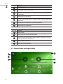
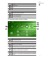
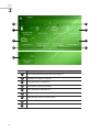
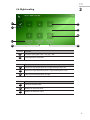
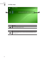
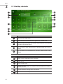
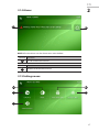
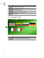
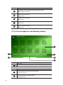
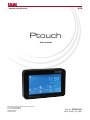
MCB
•Remote control panel
Ptouch
User manual
Ragainės g. 100, LT-78109 Šiauliai, Lithuania
Tel. (+370 41) 540415
Fax. (+370 41) 540417
[email protected]
www.salda.lt
Art.-no. PRGPU081
MCB_P0097_AZ_0001
TABLE OF
CONTENTS
1 GENERAL INFORMATION ...................................................................................................... 3
2 USER MANUAL .......................................................................................................................... 3
2.1 Main window ..................................................................................................................... 3
2.2 Temperature setting window ...................................................................................... 4 2.3 Operation mode selection window .......................................................................... 5
2.4 Menu .................................................................................................................................... 6
2.5 Device status window .................................................................................................... 7
2.6 Night cooling ..................................................................................................................... 9
2.7 Fans boost ........................................................................................................................ 10
2.8 Set points ......................................................................................................................... 11
2.9 Filter timer ........................................................................................................................ 12
2.10 Heating season settings ............................................................................................13
2.11 Date and time ............................................................................................................... 14
2.11 Weekly scheduler .........................................................................................................15
2.12 Holiday scheduler ....................................................................................................... 16
2.14 Alarms ............................................................................................................................. 17
2.15 Settings menu .............................................................................................................. 17
2.15.1 Language selection ..........................................................................................18
2.15.2 Theme selection .................................................................................................19
2.15.3 Child protection lock settings .......................................................................19
2.15.4 Screen brightness and dimming settings ................................................ 20
2.15.5 Sound settings ................................................................................................... 21
EN
1
GENERAL INFORMATION
Ptouch remote control panel is designed for:
• SALDA ventilation units and other devices based on PRV, MCB or ECO controllers;
• Modbus-controlled devices.
Remote control panels guarantee optimal comfort of operation, monitoring, maintenance and service. All
operations can be performed using remote panel, which displays the status of the system, fault reports
and service settings.
Features:
• Simple use;
• Surface mounted;
• 4.3” touch-screen;
• Display of functions and set points;
• Acoustic response to touch;
• Maximum fan speed setting for limited time period (BOOST);
• Blocking (locking) - protection from children;
• User menu for fan speed, mode, status, CO2 control settings.
Package includes:
• 1x Ptouch control panel;
• 1x Cable;
• 1x Manual;
• 2x Fastening elements (screw 3,9 x 25 DIN 7981 – 2 pcs nylon plug 5x25 – 2 pcs, hammered steel plug
12x30 – 2 pcs).
2
USER MANUAL
2.1 Main window
B1
I2
I1
B3
I3
I5
I4
B2
B5
I7
B4
I6
3
EN
2
Number
Function
I1
Date and time.
I2
Information / alert / status box.
I3
Operating mode (comfort, max boost, stand-by, building protection
or economy).
I4
Temperature of outside air
I5
Desired room temperature (in comfort mode) or selected operating
mode icon.
I6
Temperature of extracted air (room temperature).
I7
Temperature of supplied air.
Number
Function
B1
Menu button.
B2
Click to set a desired room temperature.
B3
Click to choose the operating mode (comfort, max boost, stand-by,
building protection or economy).
B4
Show previous indicators.
B5
Show next set of indicators.
2.2 Temperature setting window
B1
I2
I1
B2
B3
I3
4
EN
Number
I1
Window name.
I2
Time.
I3
Newly set desired room temperature (extracted air temperature).
Number
2
Function
Function
B1
Back. Return to previous window.
B2
Decrease set temperature.
B3
Increase set temperature.
2.3 Operation mode selection window
B3
I1
B1
B5
B2
B4
Number
I1
Number
Function
Current operating mode.
Function
B1
STANDBY – AHU is stopped.
B2
BUILDING PROTECTION – maintain minimal air movement. Temperature can be maintained depending on settings in Menu → Set Points.
B3
ECONOMY – use decreased fan speed. Temperature can be maintained
depending on settings in Menu → Set Points.
B4
COMFORT - use normal fan speed. Temperature is maintained.
B5
MAX BOOST – Fans operate at maximum power (for a specified
period).
5
EN
2
2.4 Menu
B9
B2
B3
B1
B4
B5
B8
B6
B7
B10
B12
B13
B11
B14
B15
Number
6
Function
B1
Device status window.
B2
Night cooling settings.
B3
Period setting for max boost operating mode.
B4
Review or modify set temperatures for all modes.
B5
Filter maintenance status.
B6
Heating season settings.
B7
Set AHU control unit‘s date and time.
EN
B8
Weekly scheduler: status and modification.
B9
Show previous menu row.
B10
Show next menu row.
B11
Holiday scheduler: status and modification.
B12
List of current faults.
B13
User interface settings.
B14
Adjuster menu.
B15
Service menu.
2
2.5 Device status window
I2
I3
I1
I4
I5
I8
I6
I7
Number
Function
I1
Supplied air temperature.
I2
Exhausted air temperature.
I3
Extracted air temperature.
I4
Outside air temperature.
I5
Current operating mode.
I6
Max boost function state.
I7
Speed of the air supplying fan.
I8
Speed of the air extracting fan.
7
EN
2
I2
I3
I1
I4
I5
I8
I6
I7
I9
Number
I1
Calculated required temperature of supply air.
I2
Supplied air relative humidity.
I3
CO2 quantity in supplied air.
I4
Extracted air relative humidity.
I5
CO2 quantity in extracted air.
I6
Differential pressure in supply duct.
I7
Differential pressure in extract duct.
I8
Version of AHU’s control unit software.
I9
8
Function
EN
2
2.6 Night cooling
B1
B2
I1
I2
B3
F1
F2
F3
Number
Function
I1
Function state: green strip – on; gray – off.
I2
Set temperature indication.
Number
Function
F1
Minimum day temperature for a night cooling to be used.
F2
Maximum night temperature for a night cooling to be used.
F3
Desired room temperature at night.
Number
Function
B1
Function on/off switch.
B2
Buttons to increase value.
B3
Buttons to decrease value.
9
EN
2
2.7 Fans boost
B1
I1
B2
F1
Number
I1
Set temperature indication.
Number
F1
10
Function
Max period of boost (in seconds).
Number
B1
Function
B2
Function
Click to increase/decrease the „BOOST” function time
EN
2
2.8 Set points
B4
B3
B1
I2
I1
I3
B2
F1
F3
F2
Number
Function
I1
Set temperatures indication.
I2
State of temperature maintaining function during building protection
mode: green strip – on; gray strip – off.
I3
State of temperature maintaining function during economy mode:
green strip – on; gray strip – off.
Number
Function
F1
Room air temperature during building protection mode.
F2
Room air temperature during economy mode.
F3
Room air temperature during comfort mode.
Number
Function
B1
Buttons to increase value.
B2
Buttons to decrease value.
B3
On/off switch for temperature maintaining function during building
protection mode.
B4
On/off switch for temperature maintaining function during economy
mode.
11
EN
2
2.9 Filter timer
I1
B1
Number
I1
Number
B1
12
Function
Days remaining till filter service.
Function
Button to reset filter timer. Use only after filter replacement and at
Your own risk.
EN
2
2.10 Heating season settings
I1
F1
F2
Number
I1
Number
F1
F5
F2
Function
Current setting indication.
Function
Heating season mode:
By 3 days outside temperature average: heating season is selected
if average outside temperature exceeds the threshold;
By date: heating season starts and ends at specified days;
Heating: heating season is always active;
Cooling: heating season is never active;
Temperature threshold. Lower 3-day average of outside temperature will activate select heating season. Higher 3-day average of
outside temperature will cancel heating season.
Range: [0-30 °C]
13
EN
2
2.11 Date and time
B1
I1
B2
F1
F5
F2
F4
F3
Number
I1
Number
14
Function
Set date & time indication.
Function
F1
Year.
F2
Month.
F3
Day.
F4
Hour (24h format).
F5
Minute.
Number
Function
B1
Buttons to increase value.
B2
Buttons to decrease value.
EN
2
2.12 Weekly scheduler
I1
B2
B1
B1
I2
B3
B6
I2
B4
I5
I3
B6
I3
B5
Number
Function
I1
Selected event (light color).
I2
On/off indicator for selected event (green strip – event is on).
I3
New mode. The mode with a green strip will be set as current on occurrence of selected event.
I4
Active weekdays (green strips); inactive weekdays (gray strips).
I5
Event time (24h format).
Number
Function
B1
Event scrolls (10 weekly events available).
B2
Select event.
B3
Event on/off switch.
B4
Buttons to select mode. This mode will be activated on occurrence
of selected event.
B5
Buttons to select active weekdays for selected event.
B6
Dials to set event hour and minute.
15
EN
2
2.13 Holiday scheduler
I1
B2
B1
B1
B5
I2
B6
I5
I4
B6
B5
I3
B4
Number
I1
Selected event (light color).
I2
On/off indicator for selected event (green strip – event is on).
I3
Selected mode. The mode with a green strip will be set as current on
occurrence of selected event.
I4
Day and time to start selected event. Selected mode will be set as
current.
I5
Day and time to end selected event. Previous mode will be reset as
current.
Number
16
Function
Function
B1
Event scrolls (10 holiday events available).
B2
Select event.
B3
Event on/off switch.
B4
Buttons to select mode. This mode will be activated on occurrence
of selected event.
B5
Dials to set event starting hour and minute.
B6
Dials to set event ending and minute.
EN
2
2.14 Alarms
I1
B1
NOTE: All active alarms are also shown on a main window.
Number
I1
Number
B1
Function
List of current active alarms.
Function
Button to refresh the alarm list.
2.15 Settings menu
B2
B3
B1
B4
B5
17
EN
2
Number
Function
B1
User interface language selection.
B2
User interface theme selection.
B3
Child protection lock settings.
B4
Screen brightness and dimming settings.
B5
Sound settings.
2.15.1 Language selection
B1
Number
B1
18
Function
Buttons to select the language for user interface
2.15.2 Theme selection
B1
Number
B1
Function
Buttons to select the theme for user interface
2.15.3 Child protection lock settings
I1
F1
F5
F2
F4
F3
Number
I1
Function
Current setting indication
19
Number
Function
F1
Lock delay. Inactivity time to trigger the lock screen
Range: [OFF or 10-1200 s]
F2
Unlock PIN code. Digit 1
Range: [0-9]
F3
Unlock PIN code. Digit 2
Range: [0-9]
F4
Unlock PIN code. Digit 3
Range: [0-9]
F5
Unlock PIN code. Digit 4
Range: [0-9]
2.15.4 Screen brightness and dimming settings
I1
F1
F5
F2
F4
F3
Number
I1
Number
20
Function
Current setting indication
Function
F1
Screen brightness for normal active mode
Range: [70-100 %]
F2
Dimming level for dimmed mode
Range: [30-70 %]
F3
Inactivity time to trigger dimmed mode
Range: [30-300 s]
F4
Turn off the screen function
ON: screen is turned off after specified inactivity time
OFF: screen is never turned off
F5
Inactivity time to turn off the screen
Range: [30-2000 s]
2.15.5 Sound settings
I1
F1
Number
I1
Number
F1
Function
Current setting indication
Function
Click tone switch:
ON: Each button press is indicated by a short beep;
OFF: No beeps.
21