1
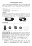
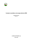
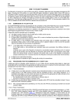
®
UAB “KALVIS”
Pramonės 15, LT-78137 Šiauliai, Lietuva
tel.: (8-41) 540556, 540558, 540565
tel./faks.: (8-41) 540561
el.p.: [email protected]
CENTRAL HEATING BOILER
KALVIS - 3 - 50 DS
CONTROL AND MAINTENANCE
MANUAL
2008
-2-
- 10 -
-3-
10. Guarantee
10.1. Manufacturer guarantees that the product conforms to technical specifications and requirements of ĮST
144948958.13:2004.
10.2. Manufacturer guarantees the following service terms from the date of sales to the consumer:
• Boiler frame – 24 months.
• Complement – 12 months.
• Consumables – 6 months.
Manufacturer is obliged to remedy all defects that have risen due to his fault if the user has not violated the
requirements for transportation, storage, connection and operation.
10.3. In case of a malfunction fill in the guarantee application form and send it to the manufacturer, manufacturer’s
authorized dealer or the company performing guarantee servicing. In urgent emergency case make a call and deliver the
application to manufacturer’s representatives on arrival.
INDEX
1. Technical data ........................................................................................................................................... 4
2. Design description .................................................................................................................................... 4
3. Transportation and storage........................................................................................................................ 4
4. Installation ................................................................................................................................................ 5
4.1. Fire precautions: .................................................................................................................................. 5
4.2. Electric installation requirements ........................................................................................................ 6
4.3. Capillary thermostats installation. ....................................................................................................... 7
I got acquainted with the requirements of installation and operation and guarantee servicing conditions. I was
informed that if the system is installed and operated in violation to this manual I lose the right to guarantee service.
4.4. Control panel connection..................................................................................................................... 7
5. Equipment control..................................................................................................................................... 7
5.1. Ignition ................................................................................................................................................ 7
5.2. Combustion adjustment ....................................................................................................................... 7
Purchaser:
5.3. Fuel supply adjustment........................................................................................................................ 7
(name, surname, signature)
5.4. Apsaugos nuo avarinių režimų. ........................................................................................................... 8
Boiler sold:
6. Operation ................................................................................................................................................. 8
Company
Date of sales:
Address
Phone
7. Safety requirements…………………………………………………………………………………….. .8
8. Acceptance certificate............................................................................................................................... 9
9. Complement.............................................................................................................................................. 9
10. Guarantee .............................................................................................................................................. 10
Boiler installed:
Company
Address
Phone
Installer
(name, surname, signature)
In case of
malfunction
please address:
Manufacturer
Company
Address
Phone
UAB “KALVIS”
Pramonės 15, LT-5419 Šiauliai, Lithuania
Telefonas: (8 41) 540565, 540556
e-mail: [email protected]
KALVIS-3-50 DS (LT)
2009.06.03
-4-
-9-
ATTENTION!
Get acquainted with this manual before installation!
In order to avoid ignition process, add fuel to the tank before it is all burnt. When adding fuel switch to manual mode
of operation (button 7), or turn the operation mode off by button 2. Add fuel quickly and set the operation mode. Before
closing the cover of the fuel tank check if the edges are free from fuel bits and if the gaskets are good. Tank cover has to
be closed at all times during operation.
1. Technical data
Central heating boiler with automated burner Kalvis-3-50 DS (hereinafter referred to as the boiler) is used for heating
various premises with central heating with enforced circulation installed by firing solid in the burner (table 1).
Burner is connected to the boiler frame. Burner is manufactured together with the fuel tank. Digital programmable
controller Omron ZEN is used to control and optimize combustion.
Main technical data
Table 1
Fuel load, m3
Maximum wood chips length, mm
Fuel consumption, kg/h (Pavg.)
Name of parameter
Pellets (calorific value 5 kWh/kg)
Chips (calorific value 3,3 kWh/kg)*
Output adjustment range, kW
Nominal output, kW
Efficiency, no less than, %
Boiler water temperature adjustment range, °C
Minimal recommended water temperature in the boiler, °C
Minimal draught in the boiler smoke outlet, Pa
Voltage, V
Electric output (motor + fan), kW
Electric protection grade
Overall dimensions of boiler with burner, not greater than: height x depth x length, mm
Weight. Not greater than, kg
* Fuel humidity 30%
Parameter value
0.9
50
3,6 ... 12
5,4 ... 18
15 ... 50
50
87
60 ... 90
60
25
400 AC
0,67
IP 55
1950 x 1300 x 3350
955
2. Design description
Design of the boiler in under constant improvement so minor inconsistencies may be present in this manual.
Constituent parts:
-
boiler Kalvis-3-50eK(eD) with the hole for burner attachment in the left or right side;
burner;
fuel tank with an auger drive;
control panel.
Boiler (see fig. 1)
Boiler (1) is specifically designed to work with the burner.
Extensive information is provided in „Boiler Kalvis-3-50 user’s manual“.
Burner (see fig. 1)
Burner frame (7) is welded form the special grade of steel. Air supplied by a fan is heated between external and
internal frame shells before entering the combustion zone. Bottom part of the burner contains a cleaning cover (10).
Air supply fan (5) is on top of the burner. Capillary thermostat (8) is attached to the top pat of the burner as well.
6.3. End of firing
When fuel in the tank is spent and the burner temperature drops below 50ºC the system turns off automatically and
the display informs user that the burner has cooled down.
To turn of the system before the fuel is used up, turn the mode of operation off by button 2 or turn the power off and
wait until the temperature of the burner will drop below 50ºC and the air supply fan stops.
Make sure there are no embers left. Turn the fuel supply in manual mode on and push any glowing embers out of the
burner into the boiler.
6.4. Cleaning
To ensure efficiency of the system periodically clean the slag in the burner and remove ash out of the boiler and clean
boilers surfaces from soot.
Time span between cleaning depends on the quality of fuel. F.e. when firing pellet with a large content of
contaminants, burner may have to be cleaned daily.
Burner should be cleaned prior to each ignition.
7. Safety requirements
•
•
•
•
•
•
•
•
•
•
•
Prohibited:
To disassemble the construction or electric installation and wiring;
Keep or dry easily flammable items near or on the system;
Ignite fuel with the help of kerosene, gasoline or other flammable liquids;
Store fuel closer than 0,5 m from the system;
Fire system with open doors or covers;
Leave children without adult supervision near a running system;
Operate the system without grounding frame of the boiler and tank;
Open boiler doors suddenly during operation. In case of need slightly open the door, than slowly open it fully;
Operate system with tank cover open;
Clean or disassemble the system with the power on;
Remove clogs, stir fuel, and add fuel with the fuel supply system running.
Necessary:
• Clean fan and motor with a dry brush;
• Observe that the electric wiring is distanced from the heated surfaces of the system no less than 70mm.
8. Acceptance certificate
Central heating boiler with tank and burner “Kalvis-3-50 DS”, factory No._______________ meets technical
specifications and is ready for operation.
Date of manufacture ___________________________
Q/A mark
___________________________
Tank with drive (see fig. 1)
Tank (2) with auger (9) is used to store and supply fuel into burner.
Gear motor (4) is mounted at the beginning of the auger drive.
The elements of the boiler control panel are shown on fig. 2.
3. Transportation and storage
Transportation of equipment is permitted only in vertical position by covered transport. During dry weather
transportation by an open transport is allowed. It is prohibited to strike, turn over equipment during the transportation or
loading-unloading procedures.
Equipment is to be stored in dry premises not containing vapors of chemically active materials.
9. Complement
1.
2.
3.
4.
5.
6.
7.
8.
9.
KALVIS-3-50 DS (LT)
Boiler „Kalvis-3-50eD(K)“
Tank for granulated fuel with the burner
Draught adjuster C20/25
Scraper
Ash scoop
Poker
User’s manual
Boiler’s „Kalvis-3-50“ user’s manual
Wooden pallet
2009.06.03
- 1 pcs.
- 1 pcs.
- 1 pcs.
- 1 pcs.
- 1 pcs.
- 1 pcs.
- 1 pcs.
- 1 pcs.
- 2 pcs.
-8-
-5-
the operation mode has been chosen, fan and fuel supply turn on automatically. To turn the operation mode (1...4) press
button 2. Pressing the button 7 again, when display reads “Man. Mode“, will allow controlling the fuel supply auger
manually. Pressing and holding button 4 will allow the fuel to be supplied into the burner manually. 3 button is used to
manually reverse the rotation of the auger.
Note: Only fuel supply auger may be controlled in a manual mode but not the fan.
Due to specifics of fuel or other reasons user may set his own fuel supply operation and pause times (T1 – heating, T2
– standby mode). Times may be adjusted only in the 1st operation mode. It is necessary to stop the program of the
controller. To stop the program press button 1 once. When in menu choose the line STOP by buttons 2 or 5 and press
button 1 again. Display will read “RUN”. Choose the line, “PARAMETER“ by buttons 2 or 5 and confirm your choice
by button 1. Now you have entered menu shown in the fig. 5 (T1- ON TIMER – duration of fuel supply to burner in
heating mode), fig. 6 (T1 – OFF TIMER – time of pause between the fuel supplies to the burner in heating mode), Fig. 7
and 8 for T2 respectively.
Set the blinking square on a parameter to be changed by buttons 2, 3, 4 or 5 and confirm the choice by button 1.
Enter the desired value by buttons 2, 3, 4, 5 and confirm it by button 1. After the parameters have been changed, return to
previous menu level by a single push of 0 button, choose the line RUN and press button 1 to run the controller program.
Only underlined parameters are permitted to be changed.
T1 W S A
ON- TIMER
TRG
RES
00.50
T1 W S A
OFF- TIMER
TRG
RES
15.00
T2 W S A
ON- TIMER
TRG
RES
00.50
T2 W S A
OFF- TIMER
TRG
RES
80.00
Fig. 5
Fig. 6
Fig. 7
Fig. 8
Note: Stop the controller program when changing times. Changing of other parameters is prohibited due to a possibility
of equipment malfunction.
5.4. Protection against malfunctions.
5.4.1. Overheating protection
If the temperature in the boiler reaches 100ºC, emergency thermostat is activated and the fuel and air supply are
turned off. Sound alarm is turned on and display notifies about activation of emergency thermostat (error). Emergency
thermostat is reset manually by unscrewing the cap (fig. 1, p.8) and pressing the red button underneath it. Reset is only
available when the boiler water temperature drops below 65ºC. When the thermostat is reset, display will stop informing
you about malfunction, sound alarm will be turned off. After igniting and firing the system again, find out the reason for
emergency thermostat activation by monitoring the system operation.
1.
2.
3.
4.
5.
6.
7.
8.
9.
10.
11.
12.
13.
14.
Boiler
Tank
Control Panel
Auger drive
Air supply fan
Air adjustment damper
Burner
Burner overheat sensor
Auger
Burner cleaning cover
Draught adjuster
Fire grate
Fire extinguishing system
Fire protection thermostat
Fig. 1 Assembly diagram of boiler with burner.
Emergency
thermostat
5.4.2. Fuel supply motor protection
When fuel supply auger is stuck or when the maximum permissible load on the motor is exceeded three times in a
row within one minute, thermal relay of the motor is activated and the motor and air fan are turned off. Display informs
user about error, i.e. about activation of the thermal relay and the sound alarm is turned on. When thermal relay is
activated turn off the power and remove the cause of sticking or overloading. After removing the cause, turn on the
power supply and choose the operation mode (1…4) by pressing button 5 again.
5.4.3. Tank protection against flame return
In order to avoid ignition of the fuel in tank an end switch is mounted on the fuel tank. Switch turns the fuel and air
supply off and turns the sound alarm on when the tank cover is open during operation. Display informs the user on the
cover status. Close tank cover to continue firing the system.
6. Operation
Boiler
temperature
Combustion
control
Fig. 2. Boiler control panel mounted on the boiler:
1.Emergency thermostat (reset button under cap). 2.Operation thermostat – used to set required temperature. 3.Combustion control
thermostat – recommended to be set to 50°C temperature.
Only adults well acquainted with the design of equipment and this manual are allowed to operate the boiler.
6.1. Choosing the operation mode
Operation mode of fuel supply and thus boiler’s heat output is chosen depending on the required heat amount. Switch
the mode to a higher one by pressing the button 5 when the system continuously operates in heating mode but fails to
reach the preset operation temperature. And vice versa: When the operation in standby mode duration exceeds that of the
heating mode, switch the operation mode to a lower one.
In any case, after changing the fuel supply operation mode adjust the air supply damper according to the flame color
(see article 5.2.4.).
6.2. Adding fuel
15mm in diameter up to 15% moisture content pellets and up to 50mm length and 30% moisture content wood chips
may be fired by a system. Heat output and efficiency of the system depends on fuel quality and type.
4. Installation
Equipment may only be installed in the premises conforming to relevant national requirements of the country of
installation.
4.1. Fire precautions:
• Minimal distances from the equipment to the walls of the premises – 0,5 m;
• Equipment must to be mounted on incombustible base. Distance to the flammable partitions may be no less than:
0,8 m from sides and rear; 1,2 m from front; 2 m from top.
• Automatic extinguishing valve (see fig. 3) is mounted on the fuel supply channel to prevent backfiring from the
burner to tank.:
- Temperature sensor activation temperature 95ºC;
KALVIS-3-50 DS (LT)
2009.06.03
-6-
-7-
- Pressure in the water mains may not exceed 0,5 Mpa.
4.3. Capillary thermostats installation
There are 4 capillary thermostats in the control panel (fig. 2):
ST1 – operation thermostat adjusts the hot water flowing out of the boiler. It’s sensor is mounted on top of the boiler
frame.
ST2 – combustion control thermostat monitors if combustion takes place. It’s capillary sensor is fixed to a top part of the
burner (fig. 1, p.8).
ST3 – emergency thermostat’s sensor mounted near operation thermostat’s ST1 sensor.
ST4 – fire protection thermostat. To be set to 75°C temperature. If fuel ignites in the fuel channel, pushes the ignited fuel
into the boiler. It’s capillary is mounted near the capillary of the automated fire extinguishing system’s.
4.4. Control panel connection
1. Auger drive
2. Drain valve
3. Temperature sensor
4. Capillary
5. Closing damper
6. Manometer with tap
7. Filter
Control panel connection works have to be performed with the power turned off and abiding to the relevant safety
regulations. Works may only be performed by qualified personnel. Panel’s principal electric diagram is provided in fig. 4
5. Control of the equipment
Form the water main
fig. 3
Automatic fire extinguishing system
To prevent fuel ignition in the fuel supply channel, a fire prevention thermostat is mounted on the channel. When
temperature on the fuel supply channel reaches 75 ºC, fuel supply auger shall operate for 30s to prevent the expansion of
flame into fuel tank. Ignited fuel will be pushed into the combustion chamber. When thermostat is activated air supply is
stopped automatically, display reads the activation of the fire prevention thermostat (error) and the sound alarm is turned
on. Only when the capillary of the thermostat cools down, display will stop showing an error message and the sound
alarm will be turned off. When the pushed fuel is removed from the combustion chamber and the capillary of the
thermostat cools down firing may be started again.
Attention! It is prohibited to fire burner with wood dust due to a possibility of an explosion!
Note: Boiler doors, loading, combustion and tank covers have to be closed tightly when firing boiler.
Control process is performed by an Omron ZEN controller that adjusts the quantity of fuel supplied and maintains the
preset operating temperature of the boiler water. LCD display of the controller allows noticing deviations from the
normal operation on time and an easy determination of cause of error.
5.1. Ignition
5.1.1.
5.1.2.
5.1.3.
5.1.4.
5.1.5.
5.1.6.
5.1.7.
5.1.8.
5.1.9.
Turn on the power switch.
Set the combustion control thermostat to a minimum position (0°C temperature).
Set the required operation temperature by an operation thermostat (no less than 60°C recommended).
Open the air supply damper (fig. 1, p.6) by about 50 %
Supply fuel manually until the fuel supply channel is filled.
Turn off the power switch and ignite the fuel in the burner..
When fuel is well lit, turn on the power switch and set the required operating mode (see article 5.3).
When boiler water temperature rises above 30°C, set the combustion control thermostat to 50°C temperature.
Adjust fuel and air supply (see article 5.2.).
Note: It is recommended to remove draught adjuster and fire grate (p11, p.12) when constantly operating boiler with the
burner.
5.2. Combustion adjustment
5.2.1. When fuel is well lit, adjust the output of the fuel supply auger by setting the mode of operation. Observe that the
unburned fuel bits do not fall out of the burner. Reduce the mode of operation should that happen.
5.2.2. Wait until the fuel is completely lit after such adjustment.
5.2.3. Open the air supply damper more when the fuel is not completely burned in the burner or the flame is red and
combustion produces soot.
5.2.4. Close the air supply damper slightly when the air blows fuel out of the burner or the flame color is light blue..
Flame has to be yellow and burn evenly.
Note: Adjust combustion again when the fuel type of it’s humidity changes.
5.3. Fuel supply adjustment
Fig 4.
Control panel connection diagram
4.2. Electric installation requirements:
Boiler controller has 4 programmable modes of fuel supply operation and pause in heating and standby modes
respectively. Depending on the temperature of the water in the boiler operated in heating or standby mode. When water
in the boiler heats up to the preset temperature, system automatically switches to the standby mode, where the
combustion is only maintained. In the heating mode fan runs continuously, in standby mode – only together with the fuel
supply auger. Boiler shall continue to operate in the standby mode until the temperature drops to 4ºC less than the preset
operating temperature. Then cycle repeats.
Table 3 provides manufacturer’s default values for fuel supply auger operation and pause times.
Table 3
Operation mode
1
2
3
4
• boiler and tank frames must be grounded;
• electric installation may only be performed by persons qualified for such jobs and/or in possession of relevant permits
or licenses;
• installation works must be performed according to a project, if relevant;
Heating mode
on, s
Firing pellets – 2
Firing chips – 8
Standby mode
pause, s
15
13
8
5.5
on, s
pause, s
Firing pellets – 2
Firing chips – 4
80
These are optimal operating modes. To choose one of the required operation modes, choose “Auto Mode” by button
7, display will inform you about the choice made. Choose the required operation mode (1...4) by pressing button 5. After
KALVIS-3-50 DS (LT)
2009.06.03