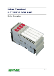
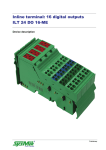
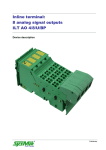
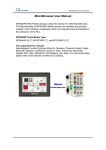
Download Device description
Transcript
InlineControlServer ICS-500 Manual Revision 4 Liability/Imprint This manual is intended to provide support for installation and usage of the device. The information is believed to be accurate and reliable. However, SysMik GmbH Dresden assumes no responsibility for possible mistakes and deviations in the technical specifications. SysMik GmbH Dresden reserves the right to make modifications in the interest of technical progress to improve our modules and software or to correct mistakes. We are grateful for any feedback and suggestions. Further information (device description, available software) can be found on our homepage www.sysmik.de. Please ask for latest information from either our local authorized representatives or directly. SysMik disclaims all warranties in case of improper use or disassembly and software modifications not described in this document or when using improper or faulty tools. Commissioning and operation of the device by qualified personnel only. All applicable regulations have to be observed. © SysMik and the SysMik logo are registered trademarks of SysMik GmbH Dresden. © IPOCS™ is trademark of SysMik GmbH Dresden; "the new intelligence of control" , "beyond © © the limits!" and "networking together!" are subject to copyright of SysMik GmbH Dresden. ® ® ® ® ® ® ® Echelon , LON , LONW ORKS , LONMARK , LonBuilder , NodeBuilder , LonManager , ® ® ® ® ® ® ® ® ® LonTalk , LonUsers , LonPoint , Digital Home , Neuron , 3120 , 3150 , LNS , i.LON , ® ® LONW ORLD , Short Stack , the Echelon logo, and the LonUsers logo are trademarks of Echelon Corporation, registered in the USA and other countries. LonLink™, LonResponse™, LonSupport™, LONews™, LonMaker™, Panoramix™, Open Systems Alliance™, LNS Powered by Echelon™, Panoramix Powered by Echelon™ and LONW ORKS Powered by Echelon™ are trademarks of Echelon Corporation. LC7093™, LC3020™, L-IP™, L-Switch™ are trademarks of LOYTEC electronics GmbH. All other trademarks mentioned in this document are registered properties of their owners. These and further trademarks are used in this document but not marked for better readability. No part of this document may be reproduced or modified in any form without prior written agreement with SysMik GmbH Dresden. Copyright © 2012 by SysMik GmbH Dresden SysMik GmbH Dresden Bertolt-Brecht-Allee 24 01309 Dresden Germany 2 Tel Fax E-Mail (sales) E-Mail (support) Homepage + 49 (0) 351 - 4 33 58 - 0 + 49 (0) 351 - 4 33 58 - 29 [email protected] [email protected] http://www.sysmik.de ICS Manual Contents Contents ICS Manual 1 Introduction 6 2 Device and System Overview 7 2.1 Programming and Configuration 7 2.2 Communication Interfaces 7 2.3 Modular I/O Terminals 7 2.4 Hardware 8 2.5 Software 9 3 Installation and Commissioning 10 3.1 Assembly 10 3.1.1 Dimensions 10 3.1.2 Mounting ICS-500 10 3.1.3 Mounting I/O Terminals 11 3.2 Connections 12 3.2.1 Connectors 12 3.2.2 Power Supply 12 3.2.3 Ethernet 17 3.2.4 RS232 18 3.2.5 TP/FT-10 19 3.3 Display and Operating Elements 19 3.3.1 Overview 19 3.3.2 Inline Supply LEDs 20 3.3.3 Service Button and LED, RUN and I/O LED 20 3.3.4 Ethernet Status 24 3.3.5 Display and Keypad / Test Mode 24 4 Console Interface, RS232 and Telnet 27 4.1 Starting RS232 Console 27 4.2 Starting Telnet Console 28 3 Contents 4 4.3 Console and Telnet Commands 28 4.3.1 General Information 28 4.3.2 All Menus 28 4.3.3 Main Menu 29 4.3.4 Submenu "device" 31 4.3.5 Submenu "router" 32 4.3.6 Submenu "modbus" (Modbus and M-Bus) 32 4.4 Diagnosis via RS232 33 5 Web Server 34 5.1 Prerequisites 34 5.2 Settings 35 5.2.1 Access 35 5.2.2 TCP/IP Settings 35 5.2.3 Device 36 5.2.4 Switch 37 5.2.5 Password 37 5.2.6 Security 37 5.2.7 LonWorks, CNIP, Router (option 'X') 38 5.2.8 Modbus / M-Bus 38 5.2.9 Backup/Restore 38 5.3 Statistics 38 5.4 DALI Functions 38 5.5 Logout 39 6 FTP Server 40 6.1 Authorization 40 6.2 Sedona Application and DALI 40 6.3 Firmware Update 40 6.4 Lexicon Files 40 7 Modbus 41 8 M-Bus 41 ICS Manual Contents ICS Manual 9 CEA-709 Router 42 9.1 Deployment 42 9.2 Configured Router Mode (Default) 42 9.3 Switch Mode 42 9.4 Repeater Mode 43 10 Troubleshooting 44 10.1 Directions for Use 44 10.1.1 Performance and Resource Management 44 10.1.2 Recover Device Settings 44 10.2 Diagnosis 44 10.3 Common Errors and their Solutions 45 10.3.1 Communication Errors 45 10.3.2 In- and Output Errors 47 11 Technical Data 49 12 Order Information 51 12.1 ICS and Accessories 51 12.2 Supported Inline Automation Terminals 51 13 Glossary 53 14 Literature 55 15 Error Reporting Form 56 5 Introduction 1 Introduction The ICS-500 is a powerful controller built on the Sedona Framework and is based upon SysMik´s proven and well established ICS (Inline Control Server) platform. It is extensible by analog and digital I/O as well as DALI master terminals. ICS-500 adds axis controller functionality such as integrated lighting, HVAC, and blind control for web based building management systems using the NiagaraAX framework. The built-in Ethernet switch with its two ports allows daisy-chain Ethernet topology without the need of additional switches. A fault tolerant ring topology can be achieved by closing the ICS-500 daisy chain to a ring with an STP (Spanning Tree Protocol) supporting switch. The web server, the RS-232 and Telnet interface provide access for configuration and maintenance. The Modbus TCP interface can be deployed for direct inter-ICS communication allowing self-contained subnetworks of ICS-500 devices without the need of a superordinate instance (e.g. Tridium's JACE). With display and keypad (option 'M'), digital and analog outputs can be manually controlled to support commissioning and service. The router function (option 'X') permits the integration of TP/FT-10 LON subsystems into the superordinated NiagaraAX system across an ICS-500(M)X. 6 ICS Manual Device and System Overview 2 Device and System Overview 2.1 Programming and Configuration ICS-500 devices are programmed, integrated, and managed with the Sedona Workbench. The configuration of the device properties can be done via web pages or console (RS232 and Telnet), unless not supported directly by the Sedona Workbench. Additionally the ICS-500 provides a web-based built-in DALI configuration tool. 2.2 Communication Interfaces The ICS-500 provides protocol interfaces for: SOX (Sedona equivalent to the Niagara FOX protocol) Modbus TCP for direct inter-ICS communication allowing self-contained sub networks of ICS-500 devices Modbus RTU (needs LonMark TP/FT-10 and IP-852 interfaces of the built-in ANSI/CEA-709 router (option 'X') Web server access, Telnet, and RS232 for configuration of device properties (IP settings, access control, Modbus, backup) and the built-in ANSI/CEA-709 router; in addition the web server provides a DALI configuration tool FTP server for software update, transmission of extension terminals configuration, DALI network configuration, Sedona application, and Sedona kits DALI for lighting control (needs DALI terminal) M-Bus for reading meters (needs M-Bus terminal) 2.3 Modular I/O Terminals The ICS-500 is a bus controller for the Inline system, thus opening up the comprehensive pool of Inline automation I/O terminals for building automation. Inline is a modular I/O system by Phoenix Contact enabling flexible and space saving assembly of automation stations. An Inline station consists of a bus controller and input and output extension I/O terminals, which vary according to quantity, type and sequence. The bus controller controls the Inline station and provides interface to the superordinate system. Up to 63 extension terminals can be connected to a bus controller. Extension terminals for almost any possible application are available: Digital in- and outputs in gradations of 1, 2, 4, 8, 16 and 32 channels per terminal TRIAC and relay outputs for switching of signals or larger loads such as lighting loads Analog inputs to measure voltages, currents, resistances and temperatures in gradations of 2, 4 and 8 channels per terminal Analog outputs for the output of currents and voltages in gradations of 1, 2, 4 and 8 channels per terminal ICS Manual 7 Device and System Overview Function terminals for complex in and output processes or gateway functions such as DALI Supply and segment terminals e.g. for configuration of separated voltage areas within an Inline station The overall width of the Inline extension terminals is 1, 2 or 4 DU (1 DU, division unit = 12.2 mm). Inline terminals are provided with a pluggable wiring level enabling pre-wiring and easy module exchange. The mechanics of the systems also allows for exchange of terminals within the station without complete dismantling. The bus controller can largely determine type and function of the terminals, thus certain in- and output functions can also be created without configuration of the station such as for commissioning tests. Hardware Local bus driver RS232 2.4 Local bus 7,5 V 24 V 0 3,3 V UL+ UANA UL- TP/FT-10 Port 0 SWITCH Port 2 Port 1 32 Bit μC RAM FLASH NVRAM 24 V RTC ) ²) 1 NT1 NT2 SH Display and keypad +24V US UBK +24V UM ) FE connection (back side of enclosure): Ground / Shield of Ethernet and TP/FT-10 ) FE connection (back side of enclosure): Functional earth groud 1 2 Figure 2.4.1: Basic circuit diagram of the ICS-500; display and keypad with option 'M' only The ICS-500 includes: Processor core with Flash, RAM, real time clock (RTC), NVRAM Two Ethernet connections with integrated Ethernet switch RS232 interface for diagnostics and configuration TP/FT-10 interface according to CEA-709 and LONMARK 8 ICS Manual Device and System Overview 2.5 Inline local bus interface and power supply for connection of up to 63 Inline automation terminals. Optionally (ICS-500M, ICS-500MX) display and operating function for manual control of the local digital and analog outputs directly from the bus controller. Software Basically the ICS includes three different programs: Boot loader, it is activated immediately after a reset of the device. Primary image, it includes all functions required for the intended use of the device and is activated by the boot loader. New Primary image versions can be loaded into the ICS via firmware download. Fallback image, it will be the emergency program in the case that the Primary image does not operate properly and has to be reloaded. It only includes the functions required to download the Primary image and is only activated if the Primary image is damaged or if the user enforces the Fallback image while activating the ICS. Fallback image can neither be modified nor loaded by the user. The simplified flowchart in figure 2.5.1. illustrates the start-up process. Start of ICS testing Primary image defect OK Fallback manually? YES NO start Primary image start Fallback image Figure 2.5.1: Simplified boot sequence diagram The Primary image comprises: Sedona Virtual Machine I/O driver Communication driver Web server CEA-709 router (option 'X') ICS Manual 9 Installation and Commissioning 3 Installation and Commissioning 3.1 Assembly 3.1.1 Dimensions Width x Height x Depth: 90 mm x 72 mm x 116 mm (3.54 inch x 2.83 inch x 4.57 inch) 90 mm [3.54 inch] 72 mm [2.83 inch] ICS-852 1226-100202-03-1 Ser.No.: NNNN-NNNN NID VID MAC NLLLLLLYLLLL NLLLLLLYLLLZ LLLXCLZZZLX 116 mm [4.57 inch] r rve Se l tro ICnSeCon Inli Figure 3.1.1.1: InlineControlServer Dimensions 3.1.2 Mounting ICS-500 Mounting position: any; vertical position preferred The device is designed for easy snap in mounting on DIN EN 50022 rails. The device has to include suitable fixtures such as terminals or grounding clamps on both sides in order to avoid the device laterally sliding off the mounting rail. Note: Only use terminals or clamps at the connection side that do not project the mounting rail by more than 30 mm in order not to impede the release of connected Ethernet plugs. 10 ICS Manual Installation and Commissioning Note: Only use clean and corrosion free mounting rails in order to ensure a safe contact between the FE terminals. 3.1.3 Mounting I/O Terminals An Inline station is assembled by plugging the individual components to each other, thus establishing the potential and bus signal connection between the individual components of the station. Figure 3.1.3.1 shows the procedure of mounting a terminal. Disconnect power to the entire station. Mount the electronics base onto the rail (A). Adjacent terminals are interlocked by their feather keys / keyways (B). First insert the feather keys of the local bus into the keyways of the preceding terminal (B1). Guide the feather keys along the keyways until they lock appropriately (B2). Ensure that the feather keys are properly connected (C2). C1 shows the common mistake that the feather keys are not inside their keyways. After mounting all electronics bases install the connectors onto their respective bases. First insert the front detent (D1). Then push the connector onto the electronics base until the rear detent locks properly (D2). 6452B010 Figure 3.1.3.1: Installation on the mounting rail (A), connection of Inline components to each other (B), connection check (C), plugging of the wiring level (D) Note: While connecting the components to each other and to the mounting rail later, please make sure that all feather keys and latches are properly snapped in! ICS Manual 11 Installation and Commissioning Note: Please consult the User Manual with regard to configuration and installation of the Inline product family (see [3]). 3.2 Connections 3.2.1 Connectors RS-232 RS-232 I/O LNK 100 Ethernet FE connector UL ICS 1) A LNK 100 Service RUN TP/FT10 NE T NT1 NT2 UM InlineControlServer 10/100BaseT Ethernet US 1.1 2.1 1.2 2.2 Supply and functional earth ground connector FE connector ²) B 1 2 3 4 5 6 7 8 1.3 2.3 1.4 2.4 Test SH TP/FT-10 1) 2) at the back side of enclosure: Ground / Shield of Ethernet and TP/FT-10 at the back side of enclosure: Functional earth ground Figure 3.2.1.1: Overview of device connections 3.2.2 Power Supply 3.2.2.1 How to Connect Power The bus controller is operated with 24 V DC. The bus controller is powered from this source and it generates the logic voltage for the logic circuit and the analog voltage for the analog circuit. The logic circuit supplies the internal bus including the communication chips of all connected automation I/O terminals. The analog circuit provides an auxiliary supply for analog signals. Note: While connecting the automation terminals please observe the derating of the logic voltage, the supply of the analog terminals, and the maximum ampacity of the terminals. Furthermore the bus controller includes connections for the supply of the mains and segment voltage of the Inline station. Figure 3.2.2.1.1 shows the basic circuit for the connections of the power supply. 12 ICS Manual Installation and Commissioning B A RS-232 I/O LNK 100 US UL ICS SH UM Brücke / Jumper 10/100BaseT NE T NT1 NT2 UL InlineControlServer US LNK 100 Service RUN TP/FT10 US UM UBK / UM + 1.1 2.1 1.2 2.2 1.3 2.3 + - 1.1 2.1 1.2 2.2 1.3 2.3 US - + - 1.4 2.4 1.4 UBK / UM 2.4 Figure 3.2.2.1.1: Supply of UM / UBK and US from different sources (A) and from a common source (B) Note: If UBK/UM and US are to be supplied from a common source, the fuse protection of the individual sections with regard to their supply requirements has to be observed. Note: The current passing through terminals and potential routing contacts must not exceed 8 A. The Functional Earth ground FE is connected to the potential routing contacts and is automatically grounded if the bus controller is snapped on a grounded mounting rail. The function of FE is to discharge interferences. Note: Functional earth ground (1.4 and. 2.4) has to be connected additionally via 1.5 mm² wire (AWG 15) and grounding terminal to the mounting rail (see figure 3.2.2.1.2). ICS Manual 13 Installation and Commissioning 6452A013 Figure 3.2.2.1.2: Connecting functional earth ground (FE) of the ICS Terminal point Name 1.1 US 2.1 1.2, 2.2 UBK / UM 1.3, 2.3 GND 1.4, 2.4 FE Function 24 V DC segment supply (segment circuit); The supplied voltage is lead to the automation terminals via the potential routing contacts. UBK: 24 V DC bus controller supply, logic supply (UL) and analog supply (UANA) UM: 24 V DC main voltage (main circuit); The supplied voltage is lead to the automation terminals via the potential routing contacts Reference ground for the internal bus and automation terminals (logic and analog circuit) and for the main and segment supply (main and segment circuit). Functional ground; Connecting the functional ground to this terminal point is mandatory (see above). The terminal point is internally connected to the potential routing contacts and the FE contact at the back side of the enclosure. Table 3.2.2.1.1: Terminal assignment of supply connector 14 ICS Manual Installation and Commissioning 3.2.2.2 Power Dissipation Calculations The power dissipation of the bus controller equals the sum of the power requirements of the bus controller itself and the power loss of the internal power supply for the whole Inline station: PICS=PO+PPERI PICS PO power dissipation of the bus controller power requirements for operating the bus controller PO=II•UN II UN PPERI P PERI = N n=1 current consumption without connected terminals (150 mA for devices with Ethernet connectors) nominal supply voltage (24 V) power loss of the internal power supply unit of the bus controller, depends on the current consumption of the rest of the Inline station (1,1V•I L n+0,7V•I An) Hint: The factors 1.1 V und 0.7 V result from the electrical efficiency of the internal power supply unit current consumption of terminal n from UL (max. 2 A in total) current consumption of terminal n from UANA (max. 0.5 A in total) Sample calculation: Power dissipation of an ICS in case of the maximum possible current draw from UL and UANA. ILn IAn P ICS=0,15A•24V+1,1V•2A+0,7V•0,5A P ICS=3,6W+2,2W+0,35W P ICS=6,15W 3.2.2.3 Current consumption calculation of an Inline station with For dimensioning an external power supply the current consumption of the entire Inline station has to be considered: IIS = IICS + IK + IAS IIS current consumption of the entire Inline - station IICS current consumption of the ICS IK current consumption of connected terminals IAS current consumption of sensors and actuators, fed by the Inline station The current consumption of an ICS is maximum 150 mA. IICS = 0.15 A The current consumption of the connected terminals can be easily determined with the IO Configurator. The following thumb rules apply: ICS Manual 15 Installation and Commissioning The current provided by UANA influences the total current directly. The current provided by UL applies to the total current with a factor of 0.4. The following formula applies: IK = IAn + IL ⋅ 0.4 IA current from UANA IL current from UL See the according datasheets in order to determine the current consumption of the connected actuators and sensors. For an estimation it is often already sufficient to check, whether the supply can be provided completely by the ICS, that is without power or boost terminals. For circuits UL and UANA, the programming system provides means for calculating the power consumption. Without power and boost terminals and regardless of the circuits UM und US, a maximum current consumption of the ICS with connected terminals is 1.5 A. In addition there are the current requirements of the sensors and actuators, whereas the current through feather keys and keyways is limited to a maximum of 8 A. Note: When selecting an external power supply, plan sufficient reserves. Furthermore, take into account that it could come to a current increase to a multiple of the rated current in the moment of turn-on caused by input capacities. Power supplies with over current shut-down must have a sufficient response delay to avoid start-up problems. 3.2.2.4 Derating of Logic and Analog Supply As the supply of the logic voltage and the analog voltage is provided by the internal power supply of the bus controller, the power dissipation of the bus controller increases with this load. The derating must be observed when the fitting position is not vertical (see figure 3.2.2.4.1). The load of the logic voltage and the analog voltage caused by the individual automation terminals is listed in the respective data sheets. The power dissipation of the power supply unit of the bus controller caused by the connected terminals is determined as described in chapter 3.2.2.2 (PPERI). At the maximum permissible analog supply current of 0.5 A and the maximum permissible logic supply current of 2 A this results up to 50 °C in a nominal power loss of 100 % with 2.55 W. Example: At an ambient temperature of 55 °C the maximum allowable power loss of the bus controller supply unit is 50 % of the nominal power loss according to figure 3.2.2.4.1. Accordingly the maximum permissible load of this supply drops to 50 %, thus 2.55 W / 2 = 1.275 W, so the maximum permissible values for logic and analog currents have to be cut in half to 1 A and 0.25 A. If there is no load on the analog supply the logic supply may be loaded by up to 1.159 A. 16 ICS Manual Installation and Commissioning P [%] 100 90 80 70 60 50 40 30 20 10 0 0 5 10 15 20 25 30 40 45 50 55 T [°C] Figure 3.2.2.4.1: Derating of logic and analog supply 3.2.2.5 Protection Measures of Bus Terminal Supply UBK Surge / overvoltage: Input protective diode (can be destroyed by permanent overload). Polarity reversal: Serial diode in the lead path of power supply unit. In case of wrong polarity only a very low current is flowing and the fuse of the external power supply unit does not trip. Ensure protection of 2 A by fuses or through the external power supply unit. 3.2.2.6 Protective Devices of 24 V Main and Segment Supply UM and US Surge / overvoltage: Input protective diodes (can be destroyed by permanent overload). Polarity reversal: Parallel diodes. In case of wrong polarity a high current is flowing which is blowing the external fuses. Segment supply and main supply are related to the same ground potential. Note: Each 24 V voltage supply must be fused externally. The power supply unit must be capable of supplying a current four times the nominal value of the external fuse to reliably blow the fuses in case of an error. 3.2.3 Ethernet The ICS is provided with two Ethernet interfaces, which are decoupled from each other by a built-in switch. 2 shielded RJ45 connectors 10/100BaseT, automatic detection automatic MDI/MDI-X crossover detection ICS Manual 17 Installation and Commissioning Pin1 RD+ Pin2 RDPin3 TD+ Pin4 not used Pin5 not used Pin6 TDPin7 not used Pin8 not used Figure 3.2.3.1: Terminal assignment of Ethernet connector The two Ethernet connections provided by the integrated switch allow for wiring of several ICS units in a line bus without requiring external Ethernet switches or hubs. The 10/100BaseT-Ports are able to recognize and to correct an interchanged receive path pair (RD+/RD-). Thus either crossover or patch cable can be used, no matter if the remote station is another end device, a switch or a hub. Note: The maximum distance of 100 m between Ethernet devices can only be achieved using cables from category 5 on. 3.2.4 RS232 The RS232 interface supports configuration and service. Alternatively it is used as interface for Modbus RTU. The connection to a PC is made via an adapter cable (ACC-ICS-RJ12-SUB-9F, s. 12.1). Modbus RTU requires an external adapter (ACCICS-RJ12-RS485, s. 12.1). The RS232 interface is designed as RJ12 jack. Pin1 RxD Pin2 RTS Pin3 TxD Pin4 CTS Pin5 3.3 V Pin6 GND Figure 3.2.4.1: Terminal assignment of RS232 connector (DEE) 18 ICS Manual Installation and Commissioning 3.2.5 TP/FT-10 Terminal point 1 2 3 Name Function NT1 NT2 TP/FT-10 (NET) connection, independent of polarity TP/FT-10 (NET) connection, independent of polarity shield connection for TP/FT-10 SH Table 3.2.5.1: Terminal assignment of TP/FT-10 connector The pluggable twin connector allows for bus wiring and removing the ICS without bus interruption. While connecting LONWORKS technology based devices to the bus, the LONMARK wiring guidelines [6] must be observed. According to the network topology one or two network terminators such as SysMik ACC-BT have to be attached. If shielded cables are used, the shield can be connected to the SH connector in order to avoid electrostatic charging. The data bus is polarity independent. More detailed information can be found in the manual of the transceiver used [5]. 3.3 Display and Operating Elements 3.3.1 Overview RS-232 I/O LED I/O LNK 100 UL ICS Speed LED Link LED 1.1 2.1 1.2 2.2 A Service button Service LED Run LED LNK 100 Service RUN TP/FT10 NET SH NT1 NT2 UM InlineControlServer 10/100Base T Link LED Speed LED US B 1 2 3 4 5 6 7 8 Display and keypad 1.3 2.3 Test 1.4 2.4 Figure 3.3.1.1: Front view with display and operating elements The ICS-500 has Ethernet status LEDs (speed, link) Inline Diagnostic LEDs CEA-709 service button, CEA-709 service LED, RUN LED and I/O LED Buttons, LEDs, and 7-segment display (option 'M') ICS Manual 19 Installation and Commissioning 3.3.2 Inline Supply LEDs LED UL UM US State Description on UBK (24 V supply), UL (logic supply) OK off UBK, UL not OK on voltage at main circuit (+24 V DC) off no voltage at main circuit on voltage at segment circuit (+24 V DC) off no voltage at segment circuit Table 3.3.2.1: Inline supply LEDs 3.3.3 Service Button and LED, RUN and I/O LED 3.3.3.1 Overview Service buttons and LED, RUN and I/O-LED are required for fundamental device functions diagnosis of application and I/O communication sending CEA-709 service messages signalization of the wink command initializing and deleting the application memory starting the fallback image 3.3.3.2 Signaling during Boot Process After applying the supply voltage, the boot process starts, service and RUN LED light up shortly. Afterwards during the booting process, table 3.3.3.2.1 applies. LED State 1) off SVC (Service) on RUN I/O Description CEA-709 stack successfully initialized initializing CEA-709 stack off starting primary or fallback image yellow initializing driver and application green application is running red error at boot up, application stopped and not ready off initializing driver and application (see RUN LED) on driver initialized, for meaning of colors see Table 3.3.3.3.1 1) is lit when service button is pressed Table 3.3.3.2.1: LEDs during boot process 3.3.3.3 Signaling after Boot Process Once the boot process has been completed, Service, RUN and I/O LED signalize the status of application and local bus (see table 3.3.3.3.1). 20 ICS Manual Installation and Commissioning LED State Description off CEA-709 stack running SVC on service button is pressed (Service) flashing 0.5 Hz wink message received green RUN green + 1 Hz yellow pulses red green I/O yellow red application is running application is running, processor is close to maximum load no application or application stopped local bus is running local bus is not configured or configuration does not match Inline station no local bus communication Table 3.3.3.3.1: LEDs during executing application ICS Manual 21 Installation and Commissioning 3.3.3.4 Deleting the Application Memory By initializing the application memory all data related to the application such as code, network variable interface, network configuration, I/O configuration and IP configuration inside the ICS is deleted. The initialization can be either activated via service button or via console. While initializing via the service button please pay attention to the RUN LED; figure 3.3.3.4.1 shows the procedure: Disconnect device from supply voltage Push service button and keep it pushed Apply supply voltage. The RUN LED shortly lights up and goes off. Keep service button pushed. Once the RUN LED lights up in orange again, immediately release it (≤ 5 s). The RUN-LED goes off, the service button now has to be activated immediately (≤ 5 s) The RUN LED starts to light up in orange again and the button can finally be released. After completion of the boot process the RUN LED lights up in red as there is no application to start. RUNLED orange approx. 0.5 s Service button Action 1 supply off 2 press and hold button 3 supply on off orange 4 off 5 orange 6 release button press button max. 5 s max. 5 s release button red Figure 3.3.3.4.1: Procedure to delete the application memory 22 ICS Manual Installation and Commissioning 3.3.3.5 Starting the Fallback Image The fallback image (see 2.5) is required if the primary image is damaged, e.g. after failed firmware download. If the ICS detects an error while loading the primary image, the fallback image is activated automatically. If the failure occurs later during run time of the primary image, the execution of the fallback image can be enforced via service button and I/O LED; figure 3.3.3.5.1 demonstrates the procedure. Disconnect device from supply voltage Push service button and keep it pushed Apply supply voltage, the I/O LED shortly lights up in orange. Keep service button pushed. Once the I/O LED lights up in green immediately release service button (≤ 3 s). The I/O LED changes its color into orange and the service button has to be activated immediately (≤ 3 s). The I/O LED changes its color into red and the button can finally be released. The fallback image starts after a couple of seconds. The fallback mode is indicated by simultaneous flashing of the I/O LED and the RUN LED in orange with approx. 1 Hz. I/OLED orange approx. 0.5 s Service button Action 1 supply off 2 press and hold button 3 supply on off green 4 orange 5 red 6 release button press button max. 3 s max. 3 s release button Figure 3.3.3.5.1: Procedure to start the fallback image 3.3.3.6 Service Messages (option 'X') Service button and LED are part of the basic equipment of any node in LONW ORKS networks. After successful completion of the boot process, pushing the service button causes the device to send out a service message containing the node IDs of the ANSI/CEA-709 router. ICS Manual 23 Installation and Commissioning Note: Service messages can only be generated after a successful boot process. Another function is assigned to the service button during the boot process (see 3.3.3.4 and 3.3.3.5). 3.3.4 Ethernet Status The LEDs are provided separately for both ports and are located each directly next to the respective RJ-45 connector. LED State Description on network connection established LNK (Link) short off transmission of packet permanent off no network connection 100 (Speed) on 100 Mbps off 10 Mbps (if LNK is active) Table 3.3.4.1: Ethernet port LEDs 3.3.5 Display and Keypad / Test Mode 3.3.5.1 Operation in Test Mode 7-segment display LED A LED B test LED direction buttons A B test button 1 2 3 4 Test buttons 1 to 8 5 6 7 8 Figure 3.3.5.1.1: Display and keypad elements Note: Display and keypad can be controlled by the application. In delivery state all outputs like digital outputs, relays and analog outputs can be controlled manually in test mode, independent from the network (e.g. for commissioning or in case of a network breakdown). The following description does not apply to application specific programming of display and keypad. Table 3.3.5.1.1 shows an overview of the display element functions in test mode. 24 ICS Manual Installation and Commissioning LED Test 7-segmentdisplay State Description on Test mode active, outputs are controlled by the keypad. off Test mode not active, outputs are controlled by the application. digit 1, digit 2 00 – no output terminals available 01..63 – terminal, position of selected output terminal 0 – no output terminals available 1..4 – group, group of four index for analog terminals or group of eight index for digital terminals test mode not active digit 3 off LED A LED B controlled by application Table 3.3.5.1.1: Display elements of the display and keypad function In test mode an output channel is addressed by its Terminal, as position of the terminal within the station, counted beginning at the ICS. Only active terminals are counted, so orientate yourself on the diagnostics LEDs "D" on the terminals. Group, for digital output terminals: 1 for channels 1-8, 2 for channels 9-16 etc., for analog output terminals: 1 for channels 1-4, 2 for channels 5-8 Button (button 1 to 8, see figure 3.3.5.1.1), for digital output terminals button 1 for the 1st channel of the group, button 2 for the 2nd channel etc. for analog output terminals button 1 and 5 for the 1st channel of the group, button 2 and 6 for the 2nd etc. The test mode is activated by pressing the Test button. After activation the first terminal, which means the one closest to the bus controller, is initially selected. If there is no output terminal in the entire Inline station the display indicates "00.0". The selection of the automation terminals to be controlled and the group of outputs is realized by two direction buttons. By activating the right or left button only output terminals can be selected; other terminals are skipped. The test mode applies to the entire Inline station. When entering the test mode the last status determined by the application is initially kept. The application is not affected by the test mode and continues operating. When quitting the test mode by activating the Test button again, all outputs change back into the status currently set by the application. The test mode does not affect the function of the inputs. ICS Manual 25 Installation and Commissioning 3.3.5.2 Test Mode Example for Digital Output Terminal A B 1 2 3 4 5 6 7 8 Test Figure 3.3.5.2.1: Example digital output, test activated, terminal 5 / group 3. In the example of figure 3.3.5.2.1 the test mode is activated and the 3rd group is selected on the 5th terminal. If it is a terminal with digital outputs such as IB IL 24 DO 32, the channels 17 - 24 can be toggled by activating the buttons 1 – 8. 3.3.5.3 Test Mode Example for Analog Output Terminal A B 1 2 3 4 5 6 7 8 Test Figure 3.3.5.3.1: Example analog output, test activated, terminal 2 / group 1. In the example of figure 3.3.5.3.1 the 1st group on the 2nd terminal is selected in test mode. If it is a terminal with analog outputs such as IB IL AO 2/U/BP-ME, the output value on channel 1 can be increased or reduced by activating the buttons 1 and 5. The buttons 2 and 6 are assigned to the 2nd channel. The step size is approx. 10 % of the output range. 3.3.5.4 Application Specific use of Display and Keypad In addition, all elements of the display and keypad can also be controlled by the application. Thus the test mode can for example be blocked or quit by the application or be activated in different way than by the test button (e.g. via network variables). Another option is to use test mode and applications access simultaneously. Once activated the test mode takes over the control of display and operating elements; after quitting the test mode the application takes over the control again, e.g. to display values while running an operation. 26 ICS Manual Console Interface, RS232 and Telnet 4 Console Interface, RS232 and Telnet 4.1 Starting RS232 Console The following components are required to use the RS232 console functions: RS232 cable RJ12 to DSUB-9 (see 11.1) PC with terminal program, e.g. HyperTerminal on Windows XP The serial interface of the ICS-500 has to be connected to an available RS232 interface on the PC. Then the program HyperTerminal is opened in Windows XP, to be found under Start Programs Accessories Communication. Starting the program for the first time generates the request to configure the connection settings. Now the serial interface used is selected from the list Establish connection via: to make the following settings: Bits per second: 38400 Data bits: 8 Parity: None Stop bits: 1 Flow control: None After quitting the dialog with OK the dialog Properties from the File menu should be opened. After changing to the register Settings and a click on ASCII-Configuration those settings can be adapted; all selection options should be deactivated there. Now the ICS is launched by connecting the power supply and a text similar to the following appears (it can slightly differ depending on the version): SysMik GmbH Dresden www.sysmik.de ICS boot loader TIMESTAMP (BOOT): Dec 2 2010 15:07:22 Testing Testing Testing Loading RAM boot loader primary image primary image Passed Passed Passed Passed Primary application started TIMESTAMP (PRIMARY): Mar 22 2011 17:29:58 Press 'c' then ENTER to start console IMPORTANT: When a start is issued, console does not run immediately! At this stage the panel can be started by activating the <C> key followed by validating with <Enter>. Note: Please be aware that the console will not start immediately and a couple of seconds may pass before the prompt sign appears on the console screen. ICS Manual 27 Console Interface, RS232 and Telnet After the console has been started the current settings are completed and displayed by the entry prompt (ICS-cmd>_). 4.2 Starting Telnet Console For deploying the Telnet access it takes a PC with a Telnet client program, e.g. HyperTerminal on Windows. The Telnet client must authorize to the server. default password: telnet The password can be changed on the configuration Web page (see 5.2.5) default port: 23 The port can be changed on the configuration Web page (see 5.2.6). Except displaying information during booting of the device, Telnet provides essentially the same information as the RS232 console does. 4.3 Console and Telnet Commands 4.3.1 General Information Depending on the ICS model, only a subset of the listed commands may be available. The command description lists also the devices for which the respective command is available. The following abbreviations are used to explain the command formatting: n decimal number in the range 0-255 d decimal number in the range 0-65535 X hexadecimal number in the range 0-F Note: If no command has been entered for more than 5 minutes the console is automatically closed. 4.3.2 All Menus The following commands are available in all menu levels: help command help show show current values exit leave menu level Note: Depending on the ICS type and the amount of information the current settings may be shown on several pages. To process always press the <ENTER> key when requested. When entering the help command followed by <Enter> a list of available console commands is displayed. Which ones depend on the ICS type. An example: help ... Show this help screen show ... Show all settings ipboot ... Set type of ip boot-configuration 'static|bootp|dhcp' ipaddr ... Set static network ip address 'n.n.n.n' 28 ICS Manual Console Interface, RS232 and Telnet netmask ... Set static network subnet mask 'n.n.n.n' gateway ... Set static gateway ip address 'n.n.n.n' dns ... Set DNS server ip address of entry 'n' (0<n<4) to 'n.n.n.n' macaddr ... Set MAC address to 'xx:xx:xx:xx:xx:xx'. This is DANGEROUS!!! sntpsvr ... Set sntp server ip addr or domain (n.n.n.n or domain) sntpport... Set sntp port sntputc ... Set sntp utc offset in minutes '+/-' csaddr ... Set the configuration server ip address 'n.n.n.n' port ... Set port number for 'cnip|csvr' to 'n' timeout ... Set timeout for 'escrow|aggr' to 'n' (aggr=aggregation) mcastaddr.. Set multicast ip address to 'n.n.n.n' mcastport.. Set multicast port number 'n' nataddr ... Set NAT ip address to 'n.n.n.n' md5key ... Set MD5 authentication to 'key (key=MD5 hash as hexa value)' md5mode ... Set MD5 authentication mode 'on|off' ping ... Send ping to ip address 'n.n.n.n' [timeout (s)][retries <= 1000] security... Show all security settings unlock ... Unlock security configuration restrictions device ... Go to device sub-menu router ... Go to router sub-menu modbus ... Go to Modbus/M-Bus sub-menu dali ... Go to DALI sub-menu exit ... Exit console application and start IPOCS reset ... Exit console application and reset ICS The commands available are mostly self-explanatory. In any case only the functions from the current menu level are displayed. Note: To execute a command enter the command potentially followed by options and press <Enter>. To quit a submenu within the console or to close the console enter exit followed by <Enter>. 4.3.3 Main Menu ipboot ipaddr ICS Manual Defines how to get the IP address. Valid parameters: static static IP settings (default) bootp get IP settings from a bootp server dhcp get IP settings from a DHCP server IP address of the device in format n.n.n.n default 192.168.0.1 29 Console Interface, RS232 and Telnet netmask gateway dns macaddr sntpsvr sntpport sntputc security unlock IP netmask in format n.n.n.n default 255.255.255.0 gateway address either empty (default, no gateway) or in format: n.n.n.n e.g. 10.0.30.1 DNS server addresses; up to three DNS server addresses can be used, format (i = 1-3): dns i n.n.n.n or dns i (deletes address for server entry i) e.g. dns 1 212.111.225.17 default: all three entries empty (no gateway configured) MAC address in format XX:XX:XX:XX:XX:XX e.g. 00:0A:B0:01:11:13 This value is unique for each device (no default) and should only be changed in exceptional cases. SNTP server address in format n.n.n.n default 0.0.0.0 SNTP port number in format d default 0, typically 123 Set SNTP UTC offset in minutes in format d (-720 < d < 720) default 0 show security settings (read only) reset all security settings The following commands concern settings of the IP-852 channel, only available for ICS with CEA-709 router (option ‘X’): csaddr configuration server adress in format n.n.n.n default 192.168.0.254 port port settings for configuration server and CNIP CNIP port setting: format port cnip d default 1629 configuration server port setting: format port cnip d default 1628 timeout mcastaddr mcastport 30 timeout for escrow and aggregation in ms escrow setting: format timeout escrow d default 0 aggregation setting: format timeout aggr d default 16 multicast address in format n.n.n.n or empty (default, no multicast) multicast port in format d or empty (default, no multicast) ICS Manual Console Interface, RS232 and Telnet nataddr md5key NAT address in format n.n.n.n or empty (default, no NAT) MD5 key in format XXXXXXXXXXXXXXXXXXXXXXXXXXXXXXXXX or empty (default, no MD5) md5mode MD5 authorization on/off. Valid parameters: on MD5 authorization on off MD5 authorization off The following commands lead to submenus. Submenu "device" is available for all devices, the other submenus are only available if the ICS contains the respective function. device submenu for device settings, see chapter 4.3.4 router submenu for LON router settings, see chapter 4.3.5 The command ping is available with Telnet only: ping Send a ping command to an IP address (parameter 1, n.n.n.n). Optionally, the parameters timeout (parameter 2 in seconds) and number of retries (parameter 3) can be passed over. 4.3.4 Submenu "device" This submenu is available for all ICS devices. date set the date in ISO format YYYY-MM-DD (year-month-day), e.g. 2009-10-07 time set the clock in 24-h format HH:MM (hour:minute), e.g. 17:25 dst daylight saving time setting, valid parameters: auto automatic change manual on daylight saving time on, no automatic change manual off daylight saving time off, no automatic change factory reset the device to factory defaults (with confirmation) Configuration of the integrated Ethernet switch: hub Activation of port mirroring, that all Ethernet packets are forwarded similarly as with a hub, parameters: on port mirroring activated off port mirroring disabled stormrate Broadcast / multicast storm rate in percent 1…20 stormprotect Portwise activation broadcast / multicast storm protection, parameters: 1|2 on|off portwise an- und abschalten [mcast] multicast storm protection activated agingtime Aging time of forwarding tables 1…200 s trafficlimit ICS Manual 31 Console Interface, RS232 and Telnet Limitation of ingress Ethernet traffic, Parameter: 0 Keine Begrenzung 1..8 32 x 2(n-1) kbps nils commission an ICS as NiLS-DALI-interface (see help for the SysMikNiLS module in NiagaraAX), valid parameters: deco decommision comm <host-ID> bind to a Jace with <host-ID> The command devstats is available with Telnet only devstats redirect the status output of the ICS to the Telnet client. If a redirection is active, the console doesn't accept any further Telnet commands. The redirection can be canceled using the 'escape' button. 4.3.5 Submenu "router" This submenu is available for all ICS with LON router function. mode set router mode, valid parameters: off routing off, default rtr router mode rpt repeater mode switch switch mode with learning options for subnet und node subnet define learning mode for subnets, only effective in switch mode, parameters: off learning of subnets and nodes off (default) on learn subnets on node learn subnets and nodes group define learning mode for groups, only effective in switch mode, parameters: off learning of groups off (default) on learn groups 4.3.6 Submenu "modbus" (Modbus and M-Bus) mbusport set the basis port for M-Bus access; this one and the subsequent 7 ports are used for M-Bus M-Bus deactivated 0 Standard M-Bus port 2000 modbusport set the Modbus TCP ports Modbus TCP disabled 0 standard Modbus TCP 502 unitid set the Modbus TCP device ID rtu switch the Modbus-RTU on or off Standard off rtubaud set of RTU baudrate 0..4 (2400, 4800, 9600,19200, 38400) 32 ICS Manual Console Interface, RS232 and Telnet 4.4 Diagnosis via RS232 When using a terminal program without entering the console menu, the following status messages can be observed: While launching the ICS, a status text appears indicating which software components and communication stacks are loaded and whether errors occurred. After the launch a line indicating the system utilization in % is displayed every 10 seconds. The system utilization should not be at 100 % for longer periods. If parameters or configuration network variables are modified the acceptance of the modifications in the flash is displayed. The process of uploading an application is displayed. If settings of communication interfaces have been modified, the resulting reboot of communication stacks is displayed. ICS Manual 33 Web Server 5 Web Server 5.1 Prerequisites The web pages on the web server are by default available in English and German and include a menu on the left side of the window allowing access to all functions (see figure 5.2.1). Standard web browsers are used to display the web pages (for example Microsoft Internet Explorer 6/7, Firefox from 1.5, Opera from 9.2, K-Meleon from 1.0). For proper operation, the following components must be enabled in the browser: JavaScript loading pictures Cascading Style Sheets Since Java applets are included in some configuration pages, the following should be taken care of: Java is enabled in the browser. A Java plug-in of version 6 or newer is installed on the web browser PC. To modify settings the user has to log in as administrator. A guest access allows only for reading the configuration. For browser access to the homepage, the IP addresses of the ICS and the PC have to be set properly, this means that both need to be provided with a locally or worldwide unique IP address, the network masks have to match, and a possibly required internet connection must be set up. If Firewalls are used in the communication channel at least the port for the HTTP protocol (port 80) has to be opened in the direction PC to ICS. In its delivery state the ICS is provided with the IP address 192.168.0.1 / 255.255.255.0 If the PC is not in the same subnet as the ICS, first either IP address or net mask of the ICS needs to be modified via the console (see 4.3.4). Alternatively net mask and IP address of the PC can be temporarily adapted. Please contact your system administrator for that purpose. Launch the web server by entering the IP address of the ICS into the address bar of your web browser. The English homepage appears. Select another language via Language. You can get directly to the language of your choice by typing for example: http://<ICS-IP-Address>/home.asp?lang=de In this example, the German start page is opened. At the moment, German (de), English (en) and French (fr) is supported. The home page provides you with information about the product, the application and system components, and is periodically refreshed if JavaScript is enabled. 34 ICS Manual Web Server 5.2 Settings 5.2.1 Access The menu item Settings leads you to the configuration of the ICS settings. Figure 5.2.1: Login dialog During the first launch or after expiry of a user session you will be requested to enter user name and password. To modify the settings you have to login as user Administrator. In delivery status admin is the default password. Note: If possible, please use the standard password only for the very first login and immediately change it during this session. If you forget the password, you can reset the ICS to delivery state per console or by deleting the application memory (see 3.3.3.4) and login using the default password. If you only want to have a look at the settings just select the guest access and leave the password field blank. Now you can open the desired configuration page via the appropriate link highlighted in red. 5.2.2 TCP/IP Settings An ICS can retrieve the IP settings from three sources: (1) the ICS device provides them itself (configuration type static) (2) they are provided by a BOOTP server (configuration type bootp) (3) they are provided by a DHCP server (configuration type dhcp) ICS Manual 35 Web Server Note: Should the setting for option (2) not function as required, please try option (3), as the DCHP server can downgrade itself to a BOOTP server. The BOOTP server in the FactoryManager by Phoenix Contact is an example for this circumstance of use. The Windows versions function in both cases properly. Note: If a BOOTP server has been selected as source and is not available, the ICS does not finish the start process but has to be reset via the power supply and the configuration type has to be changed via the console! If a DHCP server has been selected as source and is not available, the start process continues after approx. 30 sec. with the static values and configuration type is automatically set back to static! Figure 5.2.2.1: IP configuration form of the ICS web server Figure 5.2.2.1 shows an example of the IP settings page of the ICS. The static values saved in the device are shown in the table column Static value. The column Current value shows the currently active setting, possibly provided by a BOOTP or DHCP server. The settings are saved via the button Save Settings but only become effective after a restart of the ICS, which can be initiated via the button ICS Restart. Note: If you have set BOOTP or DHCP as IP configuration type the following access to the homepage may fail as the IP address has changed. Please ask your administrator what the settings are or use the console to determine the IP address. 5.2.3 Device On this configuration page, date and time of the real time clock, the redirection of the start page can be modified, and ICS kernel and application can be uploaded. 36 ICS Manual Web Server Redirection is enabled, if the field Start Address contains an address. Whenever the browser addresses to http://ICS-IP-Address, it will be redirected to the address set in Start Address. This can be used to configure a certain language (see 5.1). Save the changes with the button Save Settings. A kernel file (*.dl) upload is initiated by the corresponding buttons. Note: Uploading a kernel or an application may cause the ICS stop working. In this case, the ICS starts its fall back application and can be brought back to normal operation by uploading the correct kernel or application images (see 2.5 and 3.3.3.5). Note: All configuration entries below NiLS-DALI commissioning need only be configured when the device is used in Tridium´s NiagaraAX framework, otherwise they have no meaning. 5.2.4 Switch Settings and status of the integrated Ethernet switch. Adjustable: Port mirroring for diagnostics with sniffer tools Broadcast and multicast storm protection Aging time. 5.2.5 Password On this configuration page you can modify all passwords. Select the desired type of password from the selection options, enter the current password in the field Enter old Password: the new password in the field Enter new Password: and repeat the new value in the field Confirm new Password: once more. After a click on the button Save Settings the modification becomes effective. If it was successful you have to login again. If an error occurred an appropriate error message is displayed. 5.2.6 Security In order to further specifically limit the access to the configuration options in the ICS, extended options are available in the page Security Configuration. The following five groups can be set up: (1) General locking of individual or all configuration options of the web server. Note: After being saved a locking selected in group 1 can only be set back either via the console or by deleting the application memory (see 3.3.3.4)! (2) Host access restrictions to the web server based on a maximum of eight IP address ranges. Note: An address range only becomes effective if the selection box behind the range is enabled. ICS Manual 37 Web Server (3) Service restrictions (4) HTTP access properties (port, basis authorization) (5) FTP access properties (port, block the "/web" folder) (6) Telnet access properties (port, enabling/disabling Telnet server) Use the key Save Settings to validate the modifications. Specific options only become effective after a reset of the ICS. Use the button Restart ICS to restart the ICS. 5.2.7 LonWorks, CNIP, Router (option 'X') This configuration entry is available for all ICS-500 with router TP/FT-10 to IP-852 (option 'X'). In the submenu CNIP, the IP-852 channel is parameterized. The IP-852 channel settings include Configuration Server, timing, multicast addressing and MD5 authentication parameters. In the submenu Router, the router can be set to one of four modes (off, router, switch, repeater). In switch mode, the learning of subnets and/or groups can be additionally defined. 5.2.8 Modbus / M-Bus This section is for configuring the Modbus TCP (port, unit ID), Modbus RTU (activated / deactivated), and M-Bus (base port number, this and 7 subsequent port numbers are used for M-Bus access). 5.2.9 Backup/Restore It is used to backup and restore selectable ICS settings. The list of available options depends on the ICS type. The name of backup files is automatically created, using the following pattern: ICS-<MAC-address hexadecimal>-SETTINGS-year-month-day.ini Note: The created file is an UTF-8 text file. 5.3 Statistics This function allows to access the statistics of the TP/FT-10 and IP-852 network interfaces and of the CEA-709 protocol stack. Further information about the displayed values can be found in [7] and [8]. Devices with CEA-709 router (option ‘X’). 5.4 DALI Functions This menu entry provides access to the DALI functions. The Administrator has full permission, the Guest has read-only rights. At the first start or after timeout of a session you are prompted to enter username and password. To change settings you have to log in as user Administrator. The default password is dali. 38 ICS Manual Web Server Note: Please use this default password only for the first log-in and change it immediately. If you have forgotten your password, you can reset the ICS to its default values either via console or by deleting the application memory (see 3.3.3.4), and then log-in using the default password. Note: It is possible to provide full access to the DALI functions without any authorization, which is accomplished by configuring a blank DALI password. This also means that concurrent host accesses are allowed then and configurations may not be set as intended. Please use this option with great care. If you just want to view the settings, select the guest access and leave the password field empty. In the next page you open the wanted system configuration function using the red marked link. For a detailed description of the DALI Configurator please refer to [4]. The function Backup/Restore is used to backup and restore DALI configurations in CSV file format. The name of backup files is automatically created, using the following pattern: ICS-<MAC-address hexadecimal>-DALI-year-month-day.csv Note: The created file is a UTF-8 text file in CSV file format. When editing this file with Microsoft Excel, you can only save it as Unicode text file. To upload such a modified file to the ICS, you have to convert it back to UTF-8 first. This can be done for example using Microsoft Word. Note: The DALI configurations are persistently stored in the FTP server. This allows you to save and restore them as binary files also via FTP access (see chapter 6.2). Each DALI network has its own configuration file, which is named dali followed by terminal number and extension .cfg and is therefore fixed to the terminal number (e.g. DALI terminal as third terminal dali3.cfg). Note: If you insert other terminals before or after the DALI terminals, the ICS recognizes it and renames the files correctly. However, if you insert terminals between existing DALI terminals, this cannot be recognized and leads to an incorrect DALI configuration. To mend this, you can FTP download the old configuration to the PC, change the file names according to the new station setup, and upload them back into the ICS. This should be done with great care. 5.5 Logout Always close open sessions via the menu function logout. Note: Configuration sessions can only be used by the client who opened the session. If an administrator session is active, the access by another client will be denied. Therefore an open administrator session should always be closed using the logout function! Note: A session is automatically closed after 5 minutes of inactivity. ICS Manual 39 FTP Server 6 FTP Server 6.1 Authorization The ICS-500 includes an FTP server which requires an FTP client to be properly authorized at the server. The password can be modified via the configuration web page (see 5.2.6). Note: The password of all FTP user accounts is identical. Changing the FTP password using the configuration websites will change it for all accounts! Note: The remote directory that you have to select in the FTP client is identical for all accounts and has to be a slash (/). Most FTP clients allow also an empty entry and use automatically the root in the selected FTP area. 6.2 Sedona Application and DALI There is an FTP area, which includes the Sedona application and the DALI configuration. The log-in to this area is: user: sys-home password: admin 6.3 Firmware Update The primary image (file of type *.dl), which includes the Sedona Virtual Machine with all components and communication interfaces for the intended operation (see 2.5) can be loaded into the device via FTP. The firmware download can also be done when a fallback image is running. user: fmwupd-primary password: admin In fallback mode, use user: fmwupd-primary password: fallbackadmin To update the kernel, overwrite the file fmwupd-primary in the ICS with the new .dl file. That is, the .dl file has to be copied into the ICS via FTP as file fmwupd-primary. After restarting the ICS the new firmware becomes valid. When running in fallback 6.4 Lexicon Files All standard configuration web pages are integrated in the ICS kernel and are not accessible via FTP. Lexicon files contain translations of these web pages into different languages. In order to transfer lexicon files, login as follows: user: admin password: admin This directory is empty by default. Lexicon files are located in a sub-folder "lexicon". To get more information how to create your own translations, please contact us via 40 ICS Manual Modbus [email protected]. We provide you with a basic lexicon collection and information on how to translate the contained files. 7 Modbus The ICS-500 supports Modbus TCP as server and client and Modbus RTU as master. The Modbus TCP server provides Modbus data points that can be read and written from Modbus TCP clients: 10,000 coils (digital outputs) 10,000 discrete inputs (digital inputs) 10,000 holding registers (analog outputs) 10,000 input registers (analog inputs) As Modbus TCP client, the ICS can read and write data points of Modbus TCP servers or gateways (to Modbus RTU or Modbus ASCII). Using Modbus RTU requires a separately available adapter. 8 M-Bus M-Bus is a common protocol for remote reading of meters. At least one function terminal of the type IB IL MBUS-PAC for connecting up to 30 meters or the IB IL RS UNI-PAC in combination with a level converter RS232 / MBus is required for operating the ICS as M-Bus master. The number of M-Bus meters with IB IL RS UNI-PAC is limited by the driving capacity of the used level converter. ICS support altogether 8 function terminals IB IL MBUS-PAC and IB IL RS UNI PAC. Thus maximum 8 M-Bus segments can be connected. ICS Manual 41 CEA-709 Router 9 CEA-709 Router 9.1 Deployment The built-in CEA-709 router can be used to connect remote CEA-709 / LON subnets over IP to each other or to a NiagaraAX station. It can be used as a standard CEA-709 configured router or as plug-and-play self-learning router (switch mode). The CEA-709 router settings can be adjusted by the console (see 4.3.5) and with a web browser (see 5.2.7). 9.2 Configured Router Mode (Default) In this mode, the built-in router operates as a standard configured router and can be integrated with LNS based network management tools like any Echelon compatible router. This mode should be used in networks with more than 10 ICS on one IP channel and heavy network load (500 packets / second), because the IP packets are addressed only to the ICS devices that connect to the CEA-709 nodes addressed in this IP packet. 9.3 Switch Mode In this mode, the built-in router operates similarly to an Ethernet switch as a learning switch and does not need any network management. Based on the destination address, the router decides whether a message is to be forwarded or not and thus avoids unnecessary traffic. Local traffic will not be forwarded. The learning of Subnet and Node addresses can be configured for learning both Subnet and Node addresses or for learning Subnet address only or it can be completely switched off. Additionally, learning of Group addresses can be enabled or disabled. The default settings are learning Subnet, Node, and Group addresses. When learning on Subnet/Node address basis, the user does not need to consider subnets spanning multiple channels. A node can even be moved from one to another channel without any concern, for the router is steadily keeping track and updating its forwarding tables. Learning unique node ID addresses (e.g. Neuron ID addresses) and broadcast addresses is not feasible. Note: The Switch mode does not support network loops! Note: Learning group addresses is only possible for messages of acknowledged or request/response service. Note: All messages with a destination address not yet learned are forwarded. 42 ICS Manual CEA-709 Router Note: The Switch mode does not scale well with larger networks. For networks with more than 500 packets / second or more than 10 routers, the Configured Router mode should be selected. 9.4 Repeater Mode In the Repeater mode, the router forwards all messages regardless of the address. Like the Switch Mode, it is fully plug-and-play, but it does not limit any traffic. Thus, it is less suitable for larger networks. For networks with more than 500 packets / second or more than 10 routers, use the Configured Router mode instead! ICS Manual 43 Troubleshooting 10 Troubleshooting 10.1 Directions for Use 10.1.1 Performance and Resource Management Sedona application, I/O control and firmware share the available resources (processor time, memory). Besides the complexity of the Sedona application and the configured cycle times, the I/O interface has an important influence on the resource utilization. Every data point consumes resources by its sheer existence (data memory), but usually it is also somehow processed by the application, thus increasing application size and CPU load. The CPU load can be evaluated by means of the RS232 diagnosis (see 4.3.3 and 4.4). Note: The CPU load should not reach 100 % over a longer period, otherwise unpredictable delays can occur. Optimize your application in this case, e.g. by increasing the task cycle times. 10.1.2 Recover Device Settings If data for the access of the devices via IP such as web server and FTP server) have got lost there are two options: Readout data from the device via console and modify them if necessary. Reset device to the default settings by deleting the application memory (see 3.3.3.4). 10.2 Diagnosis The ICS is a very complex device including many functions and interfaces. This complexity increases the number of possible failures in practical use. Usually, the most problems are caused by interactions with other devices and components. Therefore, the ICS should initially not be treated in isolation but in the context of the entire system. Different on board tools are available for error diagnosis: Inline supply LEDs for supply and diagnostics LEDs of the connected automation terminals Service, RUN and I/O-LED Ethernet status LEDs Web server Telnet and RS232 interface for console communication If you should not be able to detect the cause of an error and are in need of support from the product manufacturer, please use the error reporting form from table 14.1 and send it to your local representative or: [email protected]. 44 ICS Manual Troubleshooting 10.3 Common Errors and their Solutions 10.3.1 Communication Errors 10.3.1.1 General Prior to the detailed analysis of communication errors it should be made sure that the device is properly wired, supplied with voltage and has booted. In particular it has to be checked if All feather keys and keyways are properly snapped in The mounting rail is properly grounded The functional earth ground connection of the ICS to the mounting rail is connected by a separate lead to a grounding terminal (1.5 mm²). The RUN LED is a reliable indicator of the operating status. The boot process is only completed if it is permanently red or green. 10.3.1.2 No Communication at all, Device does not boot Watch Service, RUN, and I/O LED. Periodical simultaneously flashing of Service, RUN, and I/O LED indicates a cyclic reset of the device. If RUN and I/O LED only periodically flash simultaneously, the fallback image is running. In case of a cyclic reset please make sure that the supply voltage is not too low and the mains adapter is sufficiently dimensioned. With proper supply voltage the error may be caused by a damaged kernel. In this case launch the fallback image (see 3.3.3.5) and load a matching kernel via the TP/FT-10 interface or RS232 into the device. If the device autonomously launches the fallback image, the primary image is damaged; please load the matching kernel into the device. 10.3.1.3 No Communication via Ethernet For diagnosis please proceed with the following steps: Check the Ethernet wiring. If the LNK LED does not light up the physical connection to the Ethernet network has been interrupted. Test the network connection with the ping command. If not connected, adjust the IP settings by using either the RS232 console or by resetting the device (see 3.3.3.4) and accessing with a web browser to the default IP address. Make sure that an IP address is only assigned once. 10.3.1.4 FTP Login fails There are several causes for this error: Incompatible IP settings The standard FTP port cannot be accessed The FTP server is blocked by a firewall User name or password of the authorization is wrong For diagnosis please proceed as follows: Check Ethernet connection and IP settings. ICS Manual 45 Troubleshooting 10.3.1.5 Telnet does not work 10.3.1.6 Check the port of the FTP client and the port of the ICS with the web server configuration website or with the console. Check the settings of the firewall. The FTP port must be allowed by the firewall as exception. Note: Port 20 may have to be activated as well and the passive mode has to be set in the FTP client. Enter the proper authorization data to establish a connection. Make sure that Telnet is not disabled. This can be done either by web browser via "Settings" "Security" or by the RS232 console via submenu "security". Check the IP connection and settings. Check the settings of the firewall. The Telnet port must be allowed by the firewall. RS232 Console does not start To operate the console, the serial connection cable (see 11.1) and a PC terminal program are required. If the console does not start there may be two possible error causes: The serial connection between PC and ICS is interrupted. Check cabling between ICS and RS232 interface of your PC and terminal program settings (port number, transmission rate 38.4 kBit/s, 8 data bits, no parity, 1 stop bit, no flow control). The console can only be entered during the start process of the device. After powering-up the device, watch the terminal window. Make sure that you hit <C> and <Enter> immediately after the request for console start. 10.3.1.7 No TP/FT-10 Communication This error can either be caused by the configuration of the LONW ORKS network or by the ICS itself. Check wiring and termination of the LonWorks network (see [6]) and supply of the ICS. Check if the device is located in an area of strong alternating magnetic fields. Magnetic fields may cause interferences in the TP/FT-10 transceiver. 10.3.1.8 No IP-852 Communication 46 Check Ethernet communication (see 9.3.1.3). Check the IP settings of the IP-852 channel. Check the settings of the IP-852 configuration server and check its connection with the ping command. ICS Manual Troubleshooting 10.3.2 In- and Output Errors 10.3.2.1 General First make sure that the device boots properly and that there is no communication error (see 9.3.1). Please also check: Supply connectors are properly plugged in and latched. LEDs UM, US, UL (if available) continuously light up. Supply voltages are within the stated tolerances. The I/O LED on the ICS and the diagnostics LEDs (marked by ‚D’) on the automation terminals are important indicators of the status of the automation terminals. Note: Make sure the physical terminal arrangement matches those which is programmed in the application. Only this allows for full diagnostic use of the IO LED. Table 9.3.2.1.1 shows an overview about the possible states of the diagnostics LEDs on the automation terminals and their possible causes. State Meaning off no logic supply on logic supply ok, local bus is running flashing 0.5 Hz logic supply ok, local bus stopped flashing 2 Hz logic supply ok, peripheral error (see specific terminal documentation) flashing 4 Hz logic supply ok, error at connection between flashing and previous terminal (i.e. bad contact or plugging terminals during operation) Table 10.3.2.1.1: Meaning of the diagnostics LED D 10.3.2.2 No Access at all to In- and Outputs Check the diagnostics LED 'D' on the Inline terminals. If after finished booting up the diagnostics LED of the first terminal behind the bus controller signals an interface error (4 Hz flashing, see Table 9.3.2.1.1), the bus controller cannot access the local bus. This may occur when plugging terminals during operation, in case of an error while processing the fallback image, in case of a damaged primary image or a hardware failure. Load a proper kernel into the device (see 3.3.3.5) or exchange the device. If all diagnostics LEDs flash in a 0.5 Hz cycle, the local bus has been disrupted during operation by either removal of a terminal or by a loose connection. 10.3.2.3 No Access to a Part of the In- and Outputs Check the diagnostics LED 'D' on the terminals according to Table 9.3.2.1.1 and the I/O LED on the ICS according to Table 3.3.3.3.1. If there is a disruption of the local bus caused by a loose connection or a damaged terminal, the error position can be located using the diagnostics LEDs. If the error is caused by a wrong combination of I/O terminals it can be recognized by the I/O LED lighting in yellow color. ICS Manual 47 Troubleshooting 10.3.2.4 Individual Terminals Notify a Peripheral Error This error is generated by individual Inline terminals. It is visualized via the diagnostics LED 'D' at the respective terminal and can be read out by the application. Please see the appropriate terminal documents concerning possible failure causes. 48 ICS Manual Technical Data 11 Technical Data Processing unit Processor / clock NVRAM RTC FLASH / SDRAM LC3020 (32 Bit ARM), 50 MHz 8 KiB, data retention ≥ 10 years buffered for min. 72 h 16 MiB / 32 MiB Ethernet switch Connections MDI/MDI-X crossover Aging time 2 x 10/100BaseT automatic approx. 200 s TP/FT-10 (twisted pair bus connection for free topology) Transceiver Isolation LON vs. module TP/FT-10 1) 1 kV AC, 60 s 1) 277 V AC, continuous General electrical data Supply voltage UBK Absolute limits Current drain at nominal voltage without local bus terminals Max. current drain at nominal voltage with local bus terminals 24 V DC 19.2 V to 30 V DC ≤ 150 mA ≤ 1.5 A (7.5 V logic supply loaded with 2 A and 24 V analog supply loaded with 0.5 A) Connections Supply Type Rated cross section Ampacity Ethernet Type TP/FT-10 Type Rated cross section RS232 Type Spring-cage terminals 2 2 0.2 mm to 1.5 mm (solid or stranded), 24 - 16 AWG 8A RJ45, shielded Spring-cage terminals, pluggable T-connector 2 2 0.2 mm to 2.5 mm (solid or stranded), 24 - 12 AWG RJ12, unshielded Enclosure Width x height x depth Weight ICS Manual 90 mm x 72 mm x 116 mm approx. 270 g 49 Technical Data Environmental conditions Operating temperature Storage temperature Rel. humidity Protection standard 0 °C to 55 °C (32 °F to 122 °F) -20 °C to 70 °C (-4 °F to 158 °F) 0 % to 75 %, non condensing IP20 Connection of Inline automation terminals Number of I/O devices or automation terminals in one Inline station Max. load of logic supply (UL) Max. load of analog supply (UANA) Max. ampacity of potential routing contacts UM, US and GND (sum current) max. 63 2A 0.5 A 8A P [%] 100 90 80 70 60 Derating of logic supply and analog supply 50 40 30 20 10 0 0 EMC conformity 5 10 15 20 25 30 40 45 50 55 T [°C] 2) IEC 61000-4-2 (ESD) 6 kV contact discharge / 8 kV air discharge IEC 61000-4-3 (immunity field) 10 V/m IEC 61000-4-4 (burst) 1 kV / 2.2 kV IEC 61000-4-5 (surge) 0.5 kV asymmetric IEC 61000-4-6 (conducted immunity) 10 V/m EN 55011 (emission of ISE devices) EN 55022 (emission of ITE devices) criterion A criterion A criterion A , criterion B criterion A criterion A 2) class A 1) Safety agency hazardous voltage barrier requirements are not supported! 2) Warning: This is a Class A product (EN 55022). In a domestic environment this product may cause radio interference in which case the user may be required to take adequate measures. Table 11.1: Technical data 50 ICS Manual Order Information 12 Order Information 12.1 ICS and Accessories Variant Configuration Part no. ICS-500 ICS-500M display and keypad 1226-100202-36-9 1226-100202-37-6 ICS-500X built-in ANSI/CEA 709 router 1226-100202-38-3 ICS-500MX display and keypad, ANSI/CEA 709 router 1226-100202-39-0 Accessories ACC-ICS-RJ12-SUB-9F RS232 cable RJ12 to DSUB-9 female 1151-100231-01-2 ACC-ICS-RJ12-RS485 1151-100366-01-1 RS-485 adapter with cable 150 mm Table 12.1.1: Order information for ICS and accessories 12.2 Supported Inline Automation Terminals Device Function Part no. IB IL 230 DI 1-PAC 1 input 230 V 2861548 IB IL 24 DI4-ME 4 inputs 24 V 2863928 IB IL 24 DI8/HD-PAC 8 inputs 24 V, 1 DU 2700173 IB IL 24 DI16-ME 16 inputs 24 V 2897156 IB IL 24 DI32/HD-PAC 32 inputs 24 V 2862835 IB IL 24 DO 4-ME 4 transistor outputs 24 V / 0.5 A 2863944 IB IL 24 DO 8/HD-PAC IB IL 24 DO 16-ME IB IL 24 DO 32/HD-PAC Relay Terminals 8 transistor outputs 24 V DC/ 0.5 A, 1 DU 16 transistor outputs 24 V DC/ 0.5 A 32 transistor outputs 24 V DC/ 0.5 A 2700172 2897253 2862822 IB IL 24/230 DOR 1/W-PAC 1 change over contact 230 V / 3 A 2861881 IB IL 24/230 DOR 1/W-PC-PAC 1 change over contact 230 V / 3 A 2862178 IB IL 24/48 DOR 2/W-PAC 2 change over contact 48 V / 2 A 2863119 IB IL 24/230 DOR 4/W-PAC 4 change over contact 230 V / 3 A 2861878 IB IL 24/230 DOR 4/W-PC-PAC 4 change over contact 230 V / 3 A 2862181 IB IL 24/230 DOR 4/HC-PAC TRIAC Terminals 4 bistbl. contacts 230 V / 16 A, high inrush c. 2897716 IB IL DO 1 AC-PAC 1 x TRIAC 12-253 V AC/ 0.5 A 2861920 IB IL DO 4 AC-1A-PAC 4 x TRIAC 12-253 V AC/ 1 A 2861658 IB IL AI 2/SF-ME 2 x voltage, current 2863944 IB IL TEMP 2 RTD-PAC 2 x resistance, temperature 2861328 IB IL AI/TEMP 4 RTD-PAC 4 x voltage, resistance, temperature 2897952 IB IL AI 8/SF-PAC 8 x voltage, current 2861412 Digital Input/Output Terminals Analog Input Terminals ICS Manual 51 Order Information Analog Output Terminals IB IL AO 2/U/BP-ME IB IL AO 4/U/SF-PAC IB IL AO 4/8/U/BP-PAC 2 x voltage 4 x voltage 8 x voltage 2863957 2692050 2878036 Function and Communication Terminals IB IL DALI/PWR-PAC DALI master with DALI supply 2897813 IB IL DALI-PAC 2897910 IB IL DI 8/S0-PAC IB IL MBUS-PAC DALI master, extension terminal DALI-Master with DALI supply, Multi-Master capable 8 S0 counter inputs / digital inputs M-Bus master for up to 30 meters IB IL RS UNI-PAC Serial interface 2700893 Supply of bus electronics (UL, UANA) 230 V feed in 2861674 IB IL 230 PWR IN-PAC IB IL DOR LV-SET-PAC Spacer terminal to separate 230 V and 24 V 2861645 IB IL DALI/MM-PAC 2700605 2897020 2701927 Power and Segment Terminals IB IL 24 PWR IN/R-PAC 2861535 Table 12.2.1: Automation terminals supported by ICS Note: All terminals listed in table 11.2.1 have been approved for use with ICS. If other terminals are intended to be used, please contact SysMik [10]! 52 ICS Manual Glossary 13 Glossary Term CEA-709 ICS Manual Explanation Family of international standards on basis of the LonWorks specification for the communication protocol and mechanisms of different media according to LonMark definitions. The European equivalent is the standard EN 14908. CEA-709.1 Communication protocol „Control Network Protocol Specification“ CEA-709.3 Specification for the LONMARK TP/FT-10 channel (free topology) „Free Topology Twisted-Pair Channel Specification“ CEA-852 Standard for the tunneling protocol over IP „Tunneling Component Network Protocols Over Internet Protocol Channels" equivalent to the LonMark channel IP-852 CNIP „Control Network over IP“; abbreviation for the CEA-852 protocol EN 14908.4 Configuration Server Function for CEA-709 address assignment and management at the IP852 channel EN-14908 International CEN standard “Open Data Communication in Building Automation, Controls and Building Management – Control Network Protocol”. Specifies in accordance with the ANSI-/CEA-Standards and the LONMARK guidelines the communication protocol (part 1), the PowerLine channel (part 2), the TP/FT-10 channel (part 3), protocol tunneling IP-852 (part 4) and the implementation guidelines (part 5) Fallback Image Minimal software with emergency help functions, e.g. for download of the Primary Image; is launched if Primary Image is damaged Free topology All devices are connected to each other in any order at the TP/FT-10 channel HTTP Status-free protocol for data transfer from a WEB server to a WEB browser. ICS Bus controller for the scalable I/O terminal system Inline Modular (Phoenix Contact). IP-852 Channel type specified by LONMARK based on CEA-852 for tunneling of the CEA-709 protocol via IP internet protocol Node Bus participant in LON networks (any device) Local bus Channel for the communication of the Inline bus controller with the automation terminals within an Inline station LPA-Back-End Software module on the ICS enabling the evaluation of the CEA-709 network traffic with an protocol analyzer by Loytec L-SwitchXP Multi channel router (LOYTEC) for CEA-709 or LONW ORKS MNI „Multiple Network-Interface“ with L-Core technology by Loytec for parallel operation of up to 8 applications, including several network participants, at a time Modbus Communications protocol for programmable logic controllers (PLCs) Modbus TCP Modbus using standard Internet Protocols (TCP/IP) Neuron LONW ORKS chip, LONW ORKS communication controller etc. provided by Echelon; central part of the most existing CEA-709 nodes 53 Glossary Neuron ID / Node ID (NID) Unique number for clear identification of a network participant NiagaraAX Framework (Tridium Inc.) for management systems in Java-/Web technologies. Independent from communication protocols (BACnet / LON / MOD-Bus). NIC-709 PC network interface (LOYTEC) for LONW ORKS-/CEA-709-Networks NIC-852 PC network interface (LOYTEC) for LONW ORKS-/CEA-852 Orion Stack Implementation of the upper protocol layers of the CEA-709 standard by Loytec Primary-Image Program code including all functions for intended operation proprietary Characteristic of systems and products to be designed manufacturer specific using non-standardized protocols, which means without the free availability of tools and systems of the manufacturer they cannot be universally used by anybody. Remote access Remote access to the network for project management and maintenance purposes Ring structure Form of the free bus topology; bus topology with redundancy by connecting the terminals of a line bus. The bus remains communication enabled even in case of an interruption. Router Active element for topology structuring. Actively receives messages and sends them out after regeneration. Interference suppression, message filtering, medium coupling and connection of network segments. Sedona Framework System platform for development, deploying, integration, and management of embedded devices. It fits seamlessly into the NiagaraAX framework. Sedona Virtual Machine (VM) The Sedona virtual machine is a highly portable interpreter. It executes code written in the Sedona programming language. Service LED / button Signal LED displaying the node status. The Service button prompts sending of the Neuron ID or NID to set-up the addressing of a network participant via the network management tool Switch Device for the connection of several (even different) network segments. Each port can receive data, buffer them and transfer them according to source and target address to other ports for sending. TE/DU Division unit, 12.2 mm in the Inline-System Terminator Bus terminator. Passive network in order to avoid signal reflections on the TP/FT-10 bus line. 105 Ohm for line bus, 52.5 Ω for free topology TP/FT-10 Channel type specified by LONMARK; standard Twisted Pair technology with free topology, most common channel type, 78 kBit/s Web services Services based on WEB technologies using XML documents for data exchange such as HTTP-GET or HTTP-POST Web server Server service making the protocols of the Internet technologies available (e.g. HTTP) Table 13.1: Glossary 54 ICS Manual Literature 14 ICS Manual Literature [1] SysMik ICS-500 Sedona AX Components and Views, SysMik GmbH Dresden. [2] Inline with ICS, Manual, SysMik GmbH Dresden. [3] User manual IL SYS INST UM E: "Automation Terminals of the Inline Product Range", Phoenix Contact, Phoenix order no. 26 98 73 7. [4] DALI Configurator, Software Description, SysMik GmbH Dresden [5] LONW ORKS FTT-10A Free Topology Transceiver User’s Guide, Echelon Corporation. [6] LONW ORKS Wiring Guidelines, SysMik GmbH Dresden. [7] ANSI/CEA-709.1-B, Control Network Protocol Specification, 2002. [8] ANSI/CEA-852, Tunneling Device Area Network Protocols over Internet Protocol Channels, 2004. [9] IP-852 Channel User’s Guide, Echelon Corporation, 2005. [10] www.sysmik.de [11] www.phoenixcontact.com 55 Error Reporting Form 15 Error Reporting Form Please fill in form and send to [email protected] Error Report General Information Date / Time Issued by (name) Business address Project / Application Device type Serial number (Ser. No.) Node ID(s) Error (short description) Behavior of ICS LEDs (as far as available in this variant) Service (on/off/frequency) RUN (on/off/frequency) I/O (color/frequency) LNK (on/off/frequency) 100 (on/off/frequency) Test-LED (on/off) US/UM/UL (on/off) Behavior of LEDs of the attached I/O terminals Diagnostics LED "D" (on/off/frequency) Table 15.1: Error Reporting Form 56 ICS Manual


