1
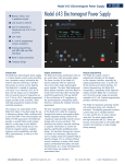
Model 480 Fluxmeter 5¾-digit DC resolution (1 part out of ±300,000) 23 Model 480 Fluxmeter Automatic drift compensation Very fast peak capture AC frequency response to 50 kHz IEEE-488 and serial interfaces Storage of parameters for up to 10 existing coils Product Description An advanced tool designed primarily for use in industrial and measurement systems settings, the Model 480 fluxmeter measures total flux from which B, flux density, and H, magnetic field strength, can be determined. The Model 480 is valuable for magnetizing, manual and automated magnet testing and sorting, and as the main component in BH loop or hysteresis measurement system applications. The Model 480 is compatible with most sensing coils and fixtures. Manual Magnet Testing A bright display and fast update rate make the Model 480 ideal for manual magnet sorting and testing. The instrument’s low drift improves productivity with fewer adjustments. Remote terminals allow for foot pedal reading reset to keep hands on the work, not the instrument. Configurable alarms give an audible signal or relay closure to signify pass/fail. Automated Magnet Testing In automated testing, time is money. The Model 480 has many features to enhance throughput. The instrument has a fast update rate and fast settling time. It recovers quickly from reading reset to start a new reading cycle. The IEEE-488 and serial computer interfaces included with the 480 can be used to control most instrument functions. Relays and analog outputs can be used for automation without a computer interface. Materials Analysis High resolution and low drift define a fluxmeter’s role in analytical measurement. The high resolution of the Model 480 is reinforced by a low noise floor. A configurable filter helps keep the readings quiet. Automatic and manual drift adjustment modes help optimize the integrators’ low drift characteristics. The IEEE-488 and serial computer interfaces included with the 480 allow automated data taking. AC Magnetic Fields Sensing coils are sensitive to AC magnetic fields but many conventional integrating fluxmeters can not measure AC fields. The Model 480 has an AC mode that enables it to measure fields over a wide frequency range using simple sensing coils. Applications are limited to field volumes as large as or larger than the coil, but for some it is an inexpensive way to make low drift AC field measurements. Drift Adjustment Adjusting or nulling the drift of an analog integrator wastes time—it can be the only unpleasant part of using an integrating fluxmeter. Lake Shore innovation brings some relief. The Model 480 has a built-in drift algorithm that continually adjusts drift when the instrument and coil are idle. It is ready when you are to make precision low-drift measurements. The adjustment algorithm has no effect during flux integration. Manual drift adjustment is also available. Magnetizing The magnetizing process places unique demands on all associated electronics. The Model 480 responds with a very fast peak capture that can keep up with the fastest magnetizing pulses. Both a positive and negative peak can be captured from the same pulse. The input of the Model 480 is protected against the high voltages present during magnetizing. www.lakeshore.com Lake Shore Cryotronics, Inc. (614) 891-2244 fax: (614) 818-1600 e-mail: [email protected] 24 Model 480 Fluxmeter Model 480 Rear Panel Line input assembly Serial I/O interface IEEE-488 interface Terminal block (for relays and analog signals)* Coil input for user coils Probe input for Lake Shore probes *The Model 480 terminal block has connections for external reset. With this feature, a foot pedal or programmable logic controller (PLC) can be used to start a new measurement cycle. The external reset is TTL-compatible and a logic low will activate a reset. The signal is internally pulled up to allow operation with a simple switch closure between pins 12 and 13. Display The Model 480 has a 2-line by 20-character vacuum fluorescent display. During normal operation, the display is used to report field readings and give results of other features such as max/min or relative. When setting instrument parameters, the display gives the operator meaningful prompts and feedback to simplify operation. The operator can also control display brightness. Following are three examples of the various display configurations: Normal Reading—the default mode with the display of the live DC flux reading DC Positive and Negative Peak On—the display shows both the positive and negative DC peak readings Alarm On—the alarm gives an audible and visual indication of when the flux value is selectively outside or inside a user-specified range Helmholtz and Search Coils Coils and probes wound by the user or from other manufacturers can be easily used with the Model 480. The Model 480 allows the user to save parameters for up to 10 existing coils/probes and quickly switch between them. Lake Shore also offers several sensing coils and probe assemblies for use with the Model 480 that have several conveniences. They are factory calibrated for accuracy and interchangeability. Calibration data is loaded into memory in the probe connector so it does not have to be entered by the user. Special coil assemblies are also available and can be designed to meet customer specifications. FH-Series Helmholtz Coils Lake Shore coils can be used with the Model 480 fluxmeter as well as with other fluxmeters. When used with a Model 480 fluxmeter, calibration and set up data are automatically loaded into the instrument. These probes and coils are accurately calibrated, using field standards maintained at Lake Shore. Most standards are traceable to physical standards such as a coil or probe of carefully controlled dimensions, or in some cases, to proton resonance. The coil constants are measured on the basis of the field generated by a current through the coil. See pages 46 and 47 for more information about available Helmholtz and search coils. www.lakeshore.com Lake Shore Cryotronics, Inc. (614) 891-2244 fax: (614) 818-1600 e-mail: [email protected] Model 480 Fluxmeter Model 480 Specifications Interfaces Measurement Number of inputs: 1 Input type: 2-lead, ground referenced Input resistance: 100 kΩ or 10 kΩ Maximum operating input voltage: 60 V Absolute maximum input voltage: 100 V—WARNING—voltages between 60 V and 100 V will not damage the instrument but could result in personal injury or damage to other instruments Update rate: 5 rdg/s display; 30 rdg/s IEEE-488; 30 rdg/s serial DC DC resolution: To 5¾ digits DC integrator capacitance: 1 µF nominal DC input resistance: 100 kΩ 100 kΩ 10 kΩ 10 kΩ DC ranges: 300 mVs 30 mVs 30 mVs 3 mVs DC resolution: 0.001 mVs 0.0005 mVs 0.0005 mVs 0.0005 mVs DC accuracy: Offset: ±10 µVs ±DC integrator drift; gain: ±0.25% of reading (<10 Vs/s maximum rate of change) DC minimum dF/dt: 20 µVs/min DC maximum dF/dt: 60 Vs/s DC integrator drift: ±1 µVs/min, 0.0004% full scale/min on 300 mVs range (100 kΩ input resistance constant temperature environment) DC Peak DC peak resolution: 4¾ digits DC peak integrator capacitance: 1 µF nominal AC resolution: 4¾ digits (reduced to 3¾ digits on the 30 µVs range) AC integrator capacitance: 0.1 µF nominal AC input resistance: 100 kΩ 100 kΩ 100 kΩ 100 kΩ AC ranges: 30 mVs 3 mVs 300 µVs 30 µVs AC resolution: 0.001 mVs 0.0001 mVs 0.01 µVs 0.01 µVs AC minimum reading: 3.000 mVs 0.3000 mVs 30.00 µVs 3.00 µVs AC frequency response: 2 Hz to 50 kHz AC accuracy: ±1% rdg ±10 µVs (10 Hz to 10 kHz sinusoidal); ±5% rdg ±10 µVs (2 Hz to 50 kHz sinusoidal) AC integrator drift: NA AC Peak AC peak resolution: 3¾ digits AC peak integrator capacitance: 0.1 µF nominal AC input resistance: 100 kΩ 100 kΩ 100 kΩ AC peak ranges: 30 mVs 3 mVs 300 µVs AC peak resolution: 0.01 mVs 0.001 mVs 1 µVs AC minimum reading: 0.01 mVs 0.001 mVs 5 µVs AC peak accuracy: ±5% rdg ±10 µVs (10 Hz to 10 kHz sinusoidal); ±10% rdg ±10 µVs (2 Hz to 50 kHz sinusoidal) AC peak update rate: Reduces update rate to ¼ normal Front Panel Display type: 2-line × 20-character vacuum fluorescent display Display resolution: To ±5¾ digits Display update rate: 5 rdg/s Display units: Vs, MxN, WbN, VsF, MxF, WbF, G, T, Wbcm, A, % Units multipliers: p, n, µ, m, k, M, G Annunciators: AC—AC input signal, DC—DC input signal, —positive and negative peaks, R—remote operation, —alarm on Keypad: 21 full-travel keys www.lakeshore.com Lake Shore Cryotronics, Inc. IEEE-488.2 capabilities: SH1, AH1, T5, L4, SR1, RL1, PP0, DC1, DT0, C0, E1 Serial interface: RS-232C electrical, DA-9 connector, 9600 baud External reset type: Contact closure Alarms Number: 2 Settings: High and low setpoint, Inside/Outside, Audible Actuators: Display annunciator, beeper, relays Relays Number: 3 Contacts: Normally open (NO), normally closed (NC), and common (C) Contact rating: 30 VDC at 2 A Operation: Follow high, low alarms with third relay indicating no alarm state— can be operated manually Connector: Detachable terminal block Monitor analog output Scale: ±3 V = ±full scale on Vs range Accuracy: ±1% of reading ±10 mV, (DC to 10 kHz); ±5% of reading ±10 mV, (10 kHz to 50 kHz) Minimum load resistance: 1 kΩ Connector: Detachable terminal block Corrected analog output Scale: User selected Range: ±10 V Resolution: 0.3 mV Accuracy: ±2.5 mV Minimum load resistance: 1 kΩ Connector: Detachable terminal block General DC peak input resistance: 100 kΩ 100 kΩ 10 kΩ 10 kΩ DC peak ranges: 300 mVs 30 mVs 30 mVs 3 mVs DC peak resolution: 0.01 mVs 0.001 mVs 0.001 mVs 0.001 mVs DC peak minimum reading: 0.05 mVs 0.005 mVs 0.005 mVs 0.005 mVs DC peak accuracy: Offset: ±100 µVs ±DC integrator drift; gain: ±5% of reading (<10 Vs/s maximum rate of change) DC peak maximum dF/dt: 60 Vs/s DC peak update rate: Reduces update rate to ¼ normal AC 25 Ambient temperature: 15 °C to 35 °C at rated accuracy, 5 °C to 40 °C with reduced accuracy Power requirement: 100, 120, 220, 240 VAC, +5% -10%, 50 or 60 Hz, 20 VA Size: 216 mm W × 89 mm H × 318 mm D (8.5 in × 3.5 in × 12.5 in), half rack Weight: 3 kg (6.6 lb) Approval: CE mark Ordering Information Part number 480 Description Model 480 fluxmeter Specify line power option VAC-100 100 VAC, includes U.S. power cord VAC-120 120 VAC, includes U.S. power cord VAC-220 220 VAC, includes universal Europe power cord VAC-240 240 VAC, includes universal Europe power cord VAC-120-ALL 120 VAC, includes U.S. and universal Europe power cords and all fuses Accessories included 106-739 Two 8-pin terminal block mating connectors MAN-480 Model 480 user manual Accessories available 4005 1 m (3.3 ft) long IEEE-488 (GPIB) computer interface cable assembly—includes extender required for simultaneous use of IEEE cable and auxiliary terminal block CAL-480-CERT Instrument recalibration with certificate CAL-480-DATA Instrument recalibration with certificate and data CAL-N8-DATA Calibration data for a new Model 480 RM-½ Rack mount kit for mounting one Model 480 in 483 mm (19 in) rack RM-2 Rack mount hit for mounting two Model 480s in 483 mm (19 in) rack Coils—see pages 46 and 47 for more information FNT-6R04-100 100 cm2 search coil FNT-5P04-30 30 cm2 search coil FH-2.5 Helmholtz coil, 64 mm (2.5 in) ID FH-6 Helmholtz coil, 152 mm (6 in) ID FH-12 Helmholtz coil, 305 mm (12 in) ID FCBL-6 User programmable cable with PROM, 1.5 m (5 ft) long All specifications are subject to change without notice Custom probes/coils/fixtures available — consult Lake Shore (614) 891-2244 fax: (614) 818-1600 e-mail: [email protected]