1
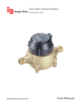
Variable Area Flow Meters Inline Liquid Flow Meter VAM-UM-00551-EN-03 (September 2014) User Manual Variable Area Flow Meters, Inline Liquid Flow Meter Page ii September 2014 User Manual CONTENTS Introduction . . . . . . . . . . . . . . . . . . . . . . . . . . . . . . . . . . . . . . . . . . . . . . . . . . . . . . . . . . . . . . . . . . . . . . . . . 4 Product Unpacking and Inspection . . . . . . . . . . . . . . . . . . . . . . . . . . . . . . . . . . . . . . . . . . . . . . . . . . . . . . . . . . .4 Operating Principle . . . . . . . . . . . . . . . . . . . . . . . . . . . . . . . . . . . . . . . . . . . . . . . . . . . . . . . . . . . . . . . . . . . . .5 Installation . . . . . . . . . . . . . . . . . . . . . . . . . . . . . . . . . . . . . . . . . . . . . . . . . . . . . . . . . . . . . . . . . . . . . . . . . . 6 Installing the Flow Meter . . . . . . . . . . . . . . . . . . . . . . . . . . . . . . . . . . . . . . . . . . . . . . . . . . . . . . . . . . . . . . 7 Installing the Test Kit Flow Meter . . . . . . . . . . . . . . . . . . . . . . . . . . . . . . . . . . . . . . . . . . . . . . . . . . . . . . . . . 8 Operation . . . . . . . . . . . . . . . . . . . . . . . . . . . . . . . . . . . . . . . . . . . . . . . . . . . . . . . . . . . . . . . . . . . . . . . . . . .9 Test Kit Information . . . . . . . . . . . . . . . . . . . . . . . . . . . . . . . . . . . . . . . . . . . . . . . . . . . . . . . . . . . . . . . . . .9 Test Procedures for Test Kit Flow Meters . . . . . . . . . . . . . . . . . . . . . . . . . . . . . . . . . . . . . . . . . . . . . . . . . . . . . . . 10 General Information . . . . . . . . . . . . . . . . . . . . . . . . . . . . . . . . . . . . . . . . . . . . . . . . . . . . . . . . . . . . . . . . 10 Standard Test Conditions . . . . . . . . . . . . . . . . . . . . . . . . . . . . . . . . . . . . . . . . . . . . . . . . . . . . . . . . . . . . . 10 Pump Test . . . . . . . . . . . . . . . . . . . . . . . . . . . . . . . . . . . . . . . . . . . . . . . . . . . . . . . . . . . . . . . . . . . . . . . 10 Tee Test . . . . . . . . . . . . . . . . . . . . . . . . . . . . . . . . . . . . . . . . . . . . . . . . . . . . . . . . . . . . . . . . . . . . . . . . 11 Relief Valves . . . . . . . . . . . . . . . . . . . . . . . . . . . . . . . . . . . . . . . . . . . . . . . . . . . . . . . . . . . . . . . . . . . . . . 11 Maintenance . . . . . . . . . . . . . . . . . . . . . . . . . . . . . . . . . . . . . . . . . . . . . . . . . . . . . . . . . . . . . . . . . . . . . . . . 12 Removal of Dust Guard . . . . . . . . . . . . . . . . . . . . . . . . . . . . . . . . . . . . . . . . . . . . . . . . . . . . . . . . . . . . . . 12 Quick Re-Coupling . . . . . . . . . . . . . . . . . . . . . . . . . . . . . . . . . . . . . . . . . . . . . . . . . . . . . . . . . . . . . . . . . 12 Test Kit Maintenance . . . . . . . . . . . . . . . . . . . . . . . . . . . . . . . . . . . . . . . . . . . . . . . . . . . . . . . . . . . . . . . . 13 Application Information . . . . . . . . . . . . . . . . . . . . . . . . . . . . . . . . . . . . . . . . . . . . . . . . . . . . . . . . . . . . . . . . . 14 Viscosity Effect (SUS/cSt) . . . . . . . . . . . . . . . . . . . . . . . . . . . . . . . . . . . . . . . . . . . . . . . . . . . . . . . . . . . . . 14 Density Effect (Specific Gravity) . . . . . . . . . . . . . . . . . . . . . . . . . . . . . . . . . . . . . . . . . . . . . . . . . . . . . . . . . 15 Flow vs Pressure Drop . . . . . . . . . . . . . . . . . . . . . . . . . . . . . . . . . . . . . . . . . . . . . . . . . . . . . . . . . . . . . . . 16 Specifications . . . . . . . . . . . . . . . . . . . . . . . . . . . . . . . . . . . . . . . . . . . . . . . . . . . . . . . . . . . . . . . . . . . . . . . 20 Materials of Construction . . . . . . . . . . . . . . . . . . . . . . . . . . . . . . . . . . . . . . . . . . . . . . . . . . . . . . . . . . . . . 20 Dimensions . . . . . . . . . . . . . . . . . . . . . . . . . . . . . . . . . . . . . . . . . . . . . . . . . . . . . . . . . . . . . . . . . . . . . . . . . 22 Standard Meter . . . . . . . . . . . . . . . . . . . . . . . . . . . . . . . . . . . . . . . . . . . . . . . . . . . . . . . . . . . . . . . . . . . 22 High Temp Meter . . . . . . . . . . . . . . . . . . . . . . . . . . . . . . . . . . . . . . . . . . . . . . . . . . . . . . . . . . . . . . . . . . 23 Test Kit . . . . . . . . . . . . . . . . . . . . . . . . . . . . . . . . . . . . . . . . . . . . . . . . . . . . . . . . . . . . . . . . . . . . . . . . . 23 September 2014 Page iii Introduction INTRODUCTION The Inline Liquid Flow Meter is a rugged industrial class inline flow rate indicator, offered in aluminum, brass or stainless steel models to monitor a wide variety of liquids. Available in seven port sizes from 1/4… 3" for flow ranges from 0.02…0.20 gpm (0.1…0.75 lpm) through 20…300 gpm (100…1100 lpm), the meters are calibrated at 0.876 specific gravity for oil or other petroleum-based fluids, 1.0 for water or other water-based fluids, or 1.18 for phosphate ester liquids. The flow meter is equipped with a 360° rotatable guard/scale which allows the meter to be installed in any orientation without regard to scale direction. Once the meter is permanently installed, the guard/scale can be rotated 360° to optimize readability. In addition, the unique spring-loaded design of this variable area flow meter decreases viscosity sensitivity and allows it to be installed in any position, including inverted, without affecting accuracy. An optional inverted scale is available for these applications. The standard flow meter is a unidirectional device. If required, a reverse flow bypass option is available for the oil, phosphate ester and water-based fluid models. Note that flow is measured in the forward direction only. • Aluminum models are offered as a rugged, low cost flow meter for monitoring noncorrosive water-based or petroleum-based fluids under operating pressures up to 3500 psi (241 bar). • Brass meters are recommended for water monitoring applications or other systems where corrosion inhibitors are not present. • Stainless Steel is available for monitoring hydraulic systems operating at pressures up to 6000 psi (414 bar) or other corrosive caustic fluids, such as acetic acid. For further construction material information, see "Materials of Construction" on page 20. PRODUCT UNPACKING AND INSPECTION Upon receipt of the product, perform the following unpacking and inspection process: If the product package is damaged, request the carrier to be present when unpacking the product. If the product is damaged and the carrier is not present, request an inspection by the carrier’s agent within 48 hours of delivery and file a claim with the carrier. A claim for equipment damage in transit is the sole responsibility of the purchaser. Carefully open the shipping package and follow any instructions marked on the exterior. Remove all packing material and carefully remove the product from the package. Retain an undamaged package and all packing material for possible use in reshipment or storage. Visually inspect the product and applicable accessories for any physical damage such as scratches, loose or broken parts, or any other sign of damage that may have occurred during shipment. Page 4 VAM-UM-00551-EN-03 September 2014 Operating Principle OPERATING PRINCIPLE The flow meter is a variable area instrument. A sharp-edged orifice, located within the piston assembly, forms an annular opening with the contoured metering cone. The piston assembly carries a cylindrical PPS/ceramic magnet that is magnetically coupled to an external indicating magnet which moves precisely in direct response to movement of the piston. A calibrated spring opposes flow in the forward direction. The Hedland variable area flow meters are the most readable products in their class. Brightly colored indicators move over the graduated, linear flow scale which contains bold, easy to read numeral and gauge marks. The enhanced resolution virtually eliminates parallax problems associated with competitive, direct reading flow meters. 16 15 7 5 13 14 8 1 6 3 4 9 2 10 W FLO 11 12 1 Orifice 9 Spider plate 2 Piston assembly 10 Retaining spring 3 Metering cone 11 Pressure seal 4 Internal magnet 12 End fitting 5 Flow indicator 13 End cap 6 Spring 14 Body 7 Flow scale 15 Guard 8 Retaining ring 16 Guard seal/bumper Table 1: Meter components September 2014 VAM-UM-00551-EN-03 Page 5 Installation INSTALLATION THIS PRODUCT SHOULD BE INSTALLED AND SERVICED BY TECHNICALLY QUALIFIED PERSONNEL TRAINED IN MAINTAINING INDUSTRIAL CLASS FLOW INSTRUMENTATION AND PROCESSING EQUIPMENT. READ INSTRUCTIONS THOROUGHLY BEFORE INSTALLING THE UNIT. IF YOU HAVE ANY QUESTIONS REGARDING PRODUCT INSTALLATION OR MAINTENANCE, CALL YOUR LOCAL SUPPLIER FOR MORE INFORMATION. OIL METERS ARE NOT RECOMMENDED FOR WATER MONITORING APPLICATIONS. IF METER IS TO BE SUBJECTED TO BOTH OIL AND WATER, BRASS WATER METERS ARE SUGGESTED. CONSULT FACTORY FOR DETAILS. THIS METER MAY CONTAIN RESIDUAL AMOUNTS OF TEST FLUID AT THE TIME OF SHIPMENT. THIS FLUID SHOULD BE REMOVED PRIOR TO INSTALLATION AS THE FLUID MAY BE INCOMPATIBLE OR HAZARDOUS WITH SOME LIQUIDS OR GASES. FAILURE TO FOLLOW THESE INSTRUCTIONS COULD RESULT IN DAMAGE TO THE EQUIPMENT. THIS STANDARD METER IS UNIDIRECTIONAL. ATTEMPTS TO FLOW FLUIDS IN THE OPPOSITE DIRECTION OF THE FLOW ARROW WILL RESULT IN THE METER ACTING AS A CHECK VALVE, CREATING A DEADHEADING SITUATION. IF THE DIFFERENTIAL PRESSURE MAGNITUDE IS GREAT ENOUGH, DAMAGE TO THE INTERNAL PARTS OF THE METER WILL RESULT. The inline flow meter is a simple device to install. However, the following measures are recommended for reliable, trouble-free operation: • Align pipe accurately. Piping should be accurately aligned and of correct length. The high pressure body of the flow meter can withstand shock and flow/pressure pulsation. However, the piping should be firmly supported by external mounting brackets, both upstream and downstream of the meter, to avoid any pipe flexing actions that could reduce meter life. • Use rigid mounting. If the flow meter inlet or outlet are to be rigidly mounted, and the opposing port is to be connected to flexible hose, the opposite end of the flexible hose must be rigidly mounted. • Use Teflon® tape for sealing NPT fitting. • Install unions. Install a union near the inlet or outlet of the meter. This will facilitate quick, easy meter removal and inspection during periodic maintenance procedures. • Mount the meter either horizontally or vertically (flow arrow pointing to either side or straight up). If the meter must be mounted inverted, special inverted scales are available from the factory. • Ensure the fluid is traveling in the direction of the flow arrow (Figure 1). • Use at least a 200 mesh (74 micron) filter. The meter will allow particulate to pass that would jam most valves and flow controls. Systems that do not have filtration should be equipped with at least a 200 mesh (74 micron) filter. Most hydraulic systems already have much finer filtration. • Dirt, ferrous metal or sealing agents, such as Teflon tape may lodge and cause malfunction. If the meter is jammed at a fixed position, follow cleaning and maintenance instructions. • Do not use thread locking compounds as thread sealant. Page 6 VAM-UM-00551-EN-03 September 2014 Installation • Do not install the flow meter near turbulence producing fittings such as elbows, reducers, close coupled valves, etc. The inline flow meter does not require flow straighteners or special lengths of straight inlet/outlet piping to stabilize turbulent flow patterns. However, to assure maximum operational reliability, avoid installation of elbows, valves and/or reducers immediately adjacent to the meter inlet. • Do not install the meter near fast-acting valves. Fast-acting valves have the potential to create high magnitude hydraulic pressure spikes. These spikes can damage the internal components of the meter, resulting in inaccuracies or malfunction. • Do not allow unidirectional meters to be operated against the direction of the flow arrow. The standard flow meter is an unidirectional flow meter. The piston acts as a check valve to block flow in the reverse direction. This causes an excessive pressure differential, which can result in damage to internal meter components. The flow meter is also available in a modified design, which offers a reverse flow bypass feature to accommodate bidirectional flow. NNOTE: Inline meters with a reverse flow bypass feature are available. Consult the factory for details. Installing the Flow Meter 1. Mount the meter so fluid is traveling in the direction of the flow arrow. Flow Direction Arrow GPM OIL LPM Figure 1: Flow direction arrow 2. Select a mounting location that is suitable for viewing and product service. To connect the flow meter into the piping system, place an open-ended wrench onto the flow meter wrench flats adjacent to the pipe connection being installed. DO NOT wrench on the opposite end of the flow meter or leakage may result. Place wrench on meter flats on the same side plumbing is being tightened. Never place wrench on meter flats opposite plumbing being tightened. Figure 2: Installing the meter September 2014 VAM-UM-00551-EN-03 Page 7 Installation 3. After installation, rotate the meter by hand to view the flow scale. Rotate meter by hand to view flow scale Never use wrench to rotate meter body when viewing flow scale Figure 3: Rotating the meter Installing the Test Kit Flow Meter 1. Mount the VA High Pressure Test Kit Flow Meter so fluid is traveling in the direction of the flow arrow. See Figure 1. 2. Install the test kit at any location in the hydraulic circuit that is suitable for viewing. To connect the test kit into the piping system, place an open-ended wrench onto the test kit valve on the inlet side or on the test kit wrench flat on the outlet side adjacent to the pipe connection being installed. DO NOT wrench on the opposite end of the test kit or leakage may result. See Figure 4. Place wrench on valve body on the same side plumbing is being tightened Never place wrench on valve body opposite plumbing being tightened Figure 4: Installing the test kit 3. Or, use quick disconnect couplings for easy connections and to keep the test kit sealed and clean when not in use. For diagrams illustrating typical test placements for the test kits, see "Test Procedures for Test Kit Flow Meters" on page 10. 4. After installation, rotate the meter by hand to view the flow scale. Page 8 VAM-UM-00551-EN-03 September 2014 Operation Rotate meter by hand to view flow scale Never use wrench to rotate meter body when viewing flow scale Figure 5: Rotating the test kit OPERATION See “Application Information” on page 14. Test Kit Information ALWAYS START WITH THE LOADING VALVE OPEN. ALL TEST KITS ARE SHIPPED WITH THE LOADING VALVE IN THE CLOSED POSITION. THE LOADING VALVE MUST BE OPENED FULLY BEFORE INITIATING FLOW AND TESTING OF THE HYDRAULIC CIRCUIT. TURN THE LOADING VALVE HANDLE COUNTERCLOCKWISE TO THE FULLY OPEN POSITION. FAILURE TO OPEN THE LOADING VALVE FULLY CAN RESULT IN INJURY TO PERSONNEL AND/OR DAMAGE TO THE EQUIPMENT. September 2014 VAM-UM-00551-EN-03 Page 9 Test Procedures for Test Kit Flow Meters TEST PROCEDURES FOR TEST KIT FLOW METERS THE INFORMATION IN THIS MANUAL IS FOR GENERAL APPLICATION ONLY. ANY INFORMATION FURNISHED BY THE MANUFACTURER OF THE MACHINE’S HYDRAULIC COMPONENTS SHOULD BE FOLLOWED. SPECIFIC SYSTEMS MAY REQUIRE SPECIFIC TEST PROCEDURES. General Information The VA High Pressure Test Kits are designed to measure flow and pressure. Power measurements are derived from the product of flow and pressure. When using a test kit, power can be calculated using the following formulas: HP = GPM x PSI 1714 HP = LPM x bar 447.4 kW = LPM x bar 600 Standard Test Conditions 1. Install the test kit as described in one of the following test procedures: a. "Pump Test" b. "Tee Test" on page 11 c. "Pump Test Using Tee Test Configuration" on page 11 d. "Relief Valve in Separate Housing" on page 11 e. "Relief Valves" on page 11 2. Open the loading valve fully by turning the handle counterclockwise. 3. Start the pump and adjust it to the rated speed. 4. Open the test kit loading valve fully and proceed with the required test procedure. 5. The test kit will indicate flow and pressure. Pump Test A tee must be installed between the pump discharge port and the return line to the tank. Be sure the fluid path is only through the pump, the hydraulic test unit and back to the tank. See Figure 6. OUT TEE IN PUMP RELIEF TANK Figure 6: Pump test 1. Plug the line to the control valve. 2. Open the test it loading valve fully to read maximum pump flow at zero pressure. 3. Close the loading valve to increase pressure from zero pressure to rated or maximum pump pressure to determine pump condition. 4. The pump flow at rated pressure can now be checked against the pump manufacturer’s specifications. A decrease in flow from zero pressure to maximum pressure indicates the pump condition. A pump that delivers a constant low flow at zero pressure and at maximum pressure suggests suction problems. Page 10 VAM-UM-00551-EN-03 September 2014 Test Procedures for Test Kit Flow Meters Tee Test A tee must be installed between the pump and control valve and connected to the inlet of the test kit. The outlet port of the test kit is connected to the tank. Pumps and relief valves can be isolated from the system and checked with the tee test. See Figure 7. Pump Test Using Tee Test Configuration 1. Plug the line to the control valve. OUT HYDRAULIC MOTOR CONTROL VALVE IN TEE PUMP RELIEF TANK Figure 7: Tee test 2. Open the test kit loading valve fully to read maximum pump flow at zero pressure. 3. Close the loading valve to increase pressure from zero pressure to rated or maximum pump pressure to determine pump condition. 4. The pump flow at rated pressure can now be checked against the pump manufacturer’s specifications. A decrease in flow from zero pressure to maximum pressure indicates the pump condition. A pump that delivers a constant low flow at zero pressure and at maximum pressure suggests suction problems. Relief Valve Test 1. Put a control valve into a power output mode with the output flow blocked, such as a cylinder at the end of its stroke. 2. Close the test kit loading valve while viewing the pressure. Pressure will increase until the relief valve opens. Record the pressure at this point. Repeat to check the relief valve adjustment. Relief Valve in Separate Housing 1. Plug any extra outlets. 2. Close the test kit loading valve and watch the pressure and flow. 3. Reconnect the control valve to the tee. Put a control valve into a power output mode with the output flow blocked, such as a cylinder at the end of its stroke. 4. Close the test kit loading valve while watching the pressure. Pressure will increase until the relief valve opens. Record the pressure at this point. Repeat to check the relief valve adjustment. Relief Valves Often relief valves will start to open before they reach their full pressure flow settings. This can be noted by comparing the pressure and flow rate readings made in step 4 in "Pump Test Using Tee Test Configuration". Any great decrease in flow rate from tests made in step 4 in "Pump Test Using Tee Test Configuration" indicates a faulty relief valve. September 2014 VAM-UM-00551-EN-03 Page 11 Maintenance MAINTENANCE BEFORE ATTEMPTING TO REMOVE THE FLOW METER FROM THE LINE, CHECK THE SYSTEM TO CONFIRM THAT LINE PRESSURE HAS BEEN REDUCED TO ZERO PSI. FAILURE TO FOLLOW THESE INSTRUCTIONS COULD RESULT IN SERIOUS PERSONAL INJURY OR DEATH AND/OR DAMAGE TO THE EQUIPMENT. 1. Remove the flow meter from the line. Remove excess piping from meter. NNOTE: It is not necessary to remove the transparent dust guard from the meter to remove the meter from the line. If you choose to remove the dust guard assembly, see "Removal of Dust Guard" on page 12. 2. Thoroughly wipe off the entire flow meter surface using mild detergent or isopropyl alcohol. DO NOT USE AROMATIC HYDROCARBONS, HALOGENATED HYDROCARBONS, KETONES OR ESTER BASED FLUIDS ON POLYCARBONATE LENS. FAILURE TO FOLLOW THESE INSTRUCTIONS COULD RESULT IN DAMAGE TO THE METER. 3. Remove the inlet cap from the flow meter, noting the sequence of disassembly for later reference (during reassembly). 4. The internal parts are secured with a retaining ring. Remove the retaining ring and the internal wetted parts from the flow meter. NNOTE: If internal parts do not slide freely from flow meter, use a wooden dowel inserted into the outlet port of the meter to push the parts out. 5. Place all parts on a clean work surface. Clean and inspect all parts. Replace any that appear worn or damaged. Check inlet port O-ring for damage and replace if required. FIELD REPLACEMENT OF THE SPRING, METERING CONE AND/OR PISTON/MAGNET ASSEMBLY MAY RESULT IN CHANGES TO THE CALIBRATION OF THE FLOW METER. 6. Reassemble the spring, then the piston/magnet assembly and the retaining ring into flow meter. 7. Install the metering cone/spider plate assembly, retaining spring, and secure with the inlet cap. 8. Reinstall the meter to the line. Removal of Dust Guard To remove the dust guard for cleaning or replacement, simply loosen the end fitting located at the bottom of the meter and slide the end cap, dust bumper, and the dust guard off the bottom of the meter, taking care to avoid damaging the O-ring seal between the end cap and the dust gland. Quick Re-Coupling This piston-type variable area flow meter is inherently less sensitive to shock and vibration than other variable area designs. The unique magnetic coupling also eliminates the need for mechanical linkages that can wear or loosen over the functional life of the meter. However, a pressure spike or extreme flow surge can cause the piston to move at such rapid speed that it disconnects the piston magnet and the external indicator ring. If this occurs, use one of these procedures to re-couple the magnet and the external indicator ring: • If the system permits, simply change flow rate from “no flow” to “full flow” allowing the moving piston to magnetically re-couple to the indicator ring. • For rigorous cyclical applications where de-coupling may occur frequently, consult the technical services staff for further recommendations. Page 12 VAM-UM-00551-EN-03 September 2014 Maintenance Test Kit Maintenance Load Valve If the valve fails to load the system, remove the valve body and check for foreign material and worn parts or seals. Flow The absence of any flow reading may indicate a seized piston assembly. Remove any material that may be preventing the piston to slide. If the test kit still fails to indicate flow, return the test kit to the factory. September 2014 VAM-UM-00551-EN-03 Page 13 Application Information APPLICATION INFORMATION Viscosity Effect (SUS/cSt) The design uses a precision machined, sharp-edged orifice and biasing calibration spring that assures operating stability and accuracy over the wide viscosity range common to many fluids. Generally, high flow models of each meter size provide good accuracy over a viscosity range of 40…500 SUS (4.2…109 cSt). Specific Gravity Oil Water Aluminum Brass T16 SST T303 SST Viton® EPR Polycarbonate Nylon Pyrex® Correction Factor Acetic Acid (Air Free) 1.06 0.909 0.971 C N R R R R C N R Acetone 0.79 1.053 1.125 R R R R N R N R R Alcohol Butyl (Butanol) 0.83 1.027 1.098 C C R R C R R R R Alcohol Ethyl (Ethanol) 0.83 1.027 1.098 C C R R C R R N R Ammonia 0.89 0.992 1.060 R C R R N R N C R Benzine 0.69 1.127 1.204 C R R C R N N R R Carbon Disulphide 1.26 0.834 0.891 R N R R R N N R R Castor Oil 0.97 0.950 1.015 C R R C R N C C R Cotton Seed Oil 0.93 0.970 1.037 C R R R R N R R R Ethylene Glycol 50/50 1.12 0.884 0.945 R R R R R R R C R Freon II 1.46 0.774 0.828 R R R R R N R R R Gasoline 0.70 1.119 1.195 R R R R R N C R R Glycerin 1.26 0.834 0.891 R R R R R R R C R Kerosene 0.82 1.033 1.104 R R R R R N R R R Liquid Propane (LPG) 0.51 1.310 1.400 R R R R R N N R R Mineral Oil 0.92 0.976 1.042 R N R R R N R R R Naphtha 0.76 1.074 1.147 R N R R R N C R R Perchloroethylene 1.62 0.735 0.786 C N R R R N N N R Petroleum Oil 0.876 1.000 1.068 R R R R R N R R R Phosphate Ester 1.18 0.862 0.921 R R R R N R N R R Phosphate Ester Base 1.26 0.833 0.891 R R R R N R N R R Phosphoric Acid (Air Free) 1.78 0.701 0.749 N N R N R N R N R Sea Water 1.03 0.922 0.985 N N C C N R R R R Synthetic Petroleum Base 1.00 0.936 1.000 R C R R R N R R R Water 1.00 0.936 1.000 N R R R N R R R R Water Glycol 50/50 1.07 0.905 0.967 R R R R R N R R R Water-in-oil 0.93 0.970 1.037 R R R R N R R R R Fluid R–Recommended N–Not Recommended C–Consult Factory Table 2: Fluid selection chart Page 14 VAM-UM-00551-EN-03 September 2014 Application Information Density Effect (Specific Gravity) Any fluid density change from stated standards has a proportional effect on meter accuracy. Special scales can be supplied if actual specific gravity decreases accuracy beyond application limits. Corrections for more or less dense fluids can be made to standard scales using the following correction factors: 1.0 Specific Gravity for water/water-based meters 0.876 Specific Gravity for petroleum-based meters MAXIMUM OPERATING PRESSURE, PSI 7000 Stainless Steel 6000 Stainless Steel 5000 TEMPERATURE DERATING CURVES 4000 Brass 3000 2000 Aluminum 1000 0 0 100 200 300 400 500 TEMPERATURE, DEGREES F CONTINUOUS TEMPERATURE INTERMITTENT TEMPERATURE Figure 8: Pressure vs temperature September 2014 VAM-UM-00551-EN-03 Page 15 Application Information Flow vs Pressure Drop 1. The pressure drop curves are valid for fluids with density and viscosity similar to factory test fluids. Fluids, especially with higher viscosity than these test fluids, will yield a higher pressure drop through the flow meter and piping system per a given flow volume. 2. A system must have adequate fluidic horsepower available to move the system fluid at a prescribed rate at a pressure adequate to overcome all pressure reducing devices, including the flow meter. Petroleum Fluids .10-1.0 .02-.20 .05-.50 1-10 0.5-5.0 0.1-1.0 0.2-2.0 FLOW, GPM 5-50 3-30 0 0 10 20-300 10-200 3/4"/1" Reverse Flow 1-1/4"/1-1/2" Reverse Flow 10-150 PRESSURE DROP, PSI 4-40 PRESSURE DROP, PSI 0.5-5.0 1-10 0.5-5.0 0.2-2.0 FLOW, GPM 1-15 0.1-1.0 5 PRESSURE DROP, PSI PRESSURE DROP, PSI 10-100 1-10 10 2-20 3.0" 10-150 FLOW, GPM PRESSURE DROP, PSI 3-30 FLOW, GPM 10-75 1/2" Reverse Flow 5-50 4-40 FLOW, GPM 1-1/4"/1-1/2" 0.2-2.0 3/4"/ 1" 1-15 PRESSURE DROP, PSI PRESSURE DROP, PSI PRESSURE DROP, PSI 1/2" .20-2.0 1/4" 3-30 2-20 0.2-2.0 0.5-5.0 FLOW, GPM 1-10 10-100 10-75 5-50 3-30 FLOW, GPM FLOW, GPM Petroleum Test Kits 1-10 Reverse Flow 0.2-2.0 0.1-1.0 0.2-2.0 0.1-1.0 0.5-5.0 1-10 Standard Test Kit 0.5-5.0 PRESSURE DROP, PSI PRESSURE DROP, PSI 1-15 4-40 3/4" / 1" 5-50 Reverse Flow 3-30 4-40 2-20 0.2-2.0 0.5-5.0 1-10 0.5-5.0 1-10 3-30 2-20 10-150 1-1/4"/ 1-1/2" Standard Test Kit PRESSURE DROP, PSI 1-15 1/2" Reverse Flow 10-100 10-150 10-75 3-30 3-30 5-50 5-50 10-75 10-100 Standard Test Kit 0.2-2.0 FLOW, GPM Page 16 FLOW, GPM VAM-UM-00551-EN-03 FLOW, GPM September 2014 Application Information Phosphate Ester 0.20-2.0 1/4" 1/2" 1-15 6 PRESSURE DROP, PSI PRESSURE DROP, PSI 0.10-1.0 .02-.20 .05-.50 4 2 0 0.0 1-10 0.5-5.0 2 0 0.5 FLOW, GPM 5-50 PRESSURE DROP, PSI PRESSURE DROP, PSI 3-30 0.5-5.0 6 2-20 4 1-10 0.2-2.0 2 0 10-100 5-50 3-30 0 1 2 3 4 5 1-15 FLOW, GPM 3/4"/1" Reverse Flow 3-30 2-20 0.5-5.0 0.1-1.0 1-1/4"/1-1/2" Reverse Flow 4-40 PRESSURE DROP, PSI PRESSURE DROP, PSI PRESSURE DROP, PSI 2 2.5 10-75 FLOW, GPM 0.2-2.0 1 10-150 1-1/4" / 1-1/2" 4-40 1-10 0 FLOW, GPM 3/4"/ 1" 1/2" Reverse Flow 0.2-2.0 0.1-1.0 4 0.2-2.0 0.5-5.0 1-10 FLOW, GPM 10-150 10-100 10-75 3-30 5-50 FLOW, GPM FLOW, GPM Phosphate Ester Test Kits Reverse Flow 0.2-2.0 0.1-1.0 0.2-2.0 0.1-1.0 1-10 0.5-5.0 Standard Test Kit 0.5-5.0 FLOW, GPM September 2014 1-15 PRESSURE DROP, PSI PRESSURE DROP, PSI 1-10 4-40 3/4" / 1" 5-50 Reverse Flow 3-30 4-40 3-30 2-20 0.5-5.0 1-10 0.2-2.0 0.5-5.0 0.2-2.0 1-10 Standard Test Kit 2-20 10-150 1-1/4"/ 1-1/2" PRESSURE DROP, PSI 1-15 1/2" Reverse Flow 10-100 10-150 10-75 3-30 3-30 5-50 5-50 FLOW, GPM VAM-UM-00551-EN-03 10-75 10-100 Standard Test Kit FLOW, GPM Page 17 Application Information API Oil 1/2" .20-2.0 PRESSURE DROP, PSI PRESSURE DROP, PSI 1/4" .10-1.0 1-15 1-10 0.5-5.0 0.2-2.0 FLOW, GPM FLOW, GPM 1-1/4"/ 1-1/2" 4-40 PRESSURE DROP, PSI PRESSURE DROP, PSI 3/4" / 1" 3-30 2-20 10-100 10-75 5-50 3-30 FLOW, GPM FLOW, GPM Water-Based Fluids 1/2" PRESSURE DROP, PSI PRESSURE DROP, PSI 0.2-2.0 .05-.50 1-10 0.5-5.0 0.1-1.0 0.2-2.0 10-100 10-75 5-50 3-30 20-275 PRESSURE DROP, PSI PRESSURE DROP, PSI 1-1/4"/1-1/2" Reverse Flow 4-40 3-30 2-20 0.2-2.0 FLOW, GPM Page 18 FLOW, GPM 0.5-5.0 0.1-1.0 1-10 0.2-2.0 20-180 3/4"/1" Reverse Flow 1-15 0.5-5.0 2-20 PRESSURE DROP, PSI PRESSURE DROP, PSI 10-150 FLOW, GPM 0.2-2.0 4-40 3-30 FLOW, GPM 3" 1-1/4"/ 1-1/2" 1-10 5-50 FLOW, GPM FLOW, GPM 1/2" Reverse Flow 3/4" / 1" 1-15 PRESSURE DROP, PSI .20-2.0 .10 -1.0 0.5-5.0 PRESSURE DROP, PSI 1/4" 10-150 10-100 10-75 5-50 1-10 3-30 FLOW, GPM VAM-UM-00551-EN-03 FLOW, GPM September 2014 Application Information Water-Based Test Kits 1-10 Reverse Flow 1-10 0.2-2.0 0.1-1.0 0.2-2.0 0.1-1.0 Standard Test Kit 0.5-5.0 5-50 Reverse Flow 3-30 2-20 0.5-5.0 0.2-2.0 0.5-5.0 0.2-2.0 1-10 FLOW, GPM 4-40 Standard Test Kit 3-30 10-150 1-1/4" / 1-1/2" PRESSURE DROP, PSI 1-15 0.5-5.0 4-40 3/4" / 1" PRESSURE DROP, PSI PRESSURE DROP, PSI 1-15 1/2" 2-20 Reverse Flow 10-100 10-150 10-75 5-50 3-30 1-10 3-30 FLOW, GPM 5-50 10-75 10-100 Standard Test Kit FLOW, GPM Water .20-2.0 ¼" 1-15 ½" ¾" / 1" 5-50 .05-.50 0.5-5.0 FLOW, GPM 0.2-2.0 3-30 2-20 22 5-50 3-30 20-275 3" 20 PRESSURE DROP, PSI 10-75 1-10 FLOW, GPM 10-150 10-100 0.5-5.0 0.2-2.0 FLOW, GPM 1¼"/ 1½" PRESSURE DROP, PSI 0.1-1.0 4-40 PRESSURE DROP, PSI .02-.20 1-10 PRESSURE DROP, PSI PRESSURE DROP, PSI .10-1.0 16 12 30-150 8 10-100 4 0 5-50 0 50 100 150 200 250 300 FLOW, GPM FLOW, GPM Caustic and Corrosive Liquids 1/2" .20-2.0 .10 -1.0 PRESSURE DROP, PSI PRESSURE DROP, PSI 1/4" 1-15 1-10 0.5-5.0 0.2-2.0 FLOW, GPM FLOW, GPM PRESSURE DROP, PSI 4-40 3-30 2-20 0.5-5.0 1-10 0.1-2.0 PRESSURE DROP, PSI 1-1/4"/ 1-1/2" 3/4" / 1" FLOW, GPM September 2014 10-100 10-75 5-50 3-30 FLOW, GPM VAM-UM-00551-EN-03 Page 19 Specifications SPECIFICATIONS Temperature Range Pressure Rating (3:1 safety factor) Standard –20…240° F (–29…116° C) High temperature and hostile environment –20…400° F (–29…205° C) continuous 400…500° F (205…260° C) intermittent Aluminum/brass models 3500 psi (241 bar) maximum Stainless steel models 1/4" and 1/2" sizes 6000 psi (414 bar) maximum 3/4…1-1/2" sizes 5000 psi (345 bar) maximum Pressure Drop See “Flow vs Pressure Drop” on page 16 for specific meter information. Accuracy ±2% of full scale Repeatability ±1% Threads SAE J1926/1, NPTF ANSI B2.2, BSPP ISO1179, Code 61 and Code 62: SAEJ518 Test Kit Pressure Gauge, Glycerin Dampened Aluminum/brass models 0…3500 psi (0…240 bar) Stainless steel models 0…6000 psi (0…400 bar 1/2", 3/4" and 1" sizes Needle valve 1-1/4" and 1-1/2" sizes Ball valve Test Kit Load Valve Produce ΔP up to 3500 psi (241 bar) PSID and 6000 psi (414 bar) PSID Materials of Construction Basic Flow Meters and Test Kits Meter Model Oil Basic & Test Kit PE Basic & Test Kit WBF Basic & Test Kit Water Basic Only 1 Body Piston Cone 2024-T351 Anodized Aluminum C360 Brass1 2024-T351 T303SS Anodized Aluminum 2024-T351 Anodized Aluminum C360 Brass 2024-T351 T303SS Anodized Aluminum 2024-T351 Anodized Aluminum C360 Brass1 2024-T351 T303SS Anodized Aluminum Spider Plate Spring Fasteners Pressure Seals Guard Retaining Retaining Ring Spring Indicator & Internal Magnet Guard Seal/ Bumper T316SS T302SS T303SS Viton® Polycarbonate SAE SAE 1070/1090 1070/1090 Carbon Carbon Steel Steel PPS/Ceramic Buna N 6063-T6 Nylon ST Aluminum T316SS T320SS T303SS EPR Polycarbonate SAE SAE 1070/1090 1070/1090 Carbon Carbon Steel Steel PPS/Ceramic EPR 6063-T6 Nylon ST Aluminum T316SS T302SS T303SS Viton® Polycarbonate T316SS T316SS PPS/Ceramic Buna N 6063-T6 Nylon ST Aluminum T316SS T302SS T303SS Viton® Polycarbonate T316SS T316SS PPS/Ceramic Buna N 6062-T6 Nylon ST Aluminum C360 Brass1 T303SS C360 Brass Scale Support End Caps 3" Models have Celcon® piston/piston ring Page 20 VAM-UM-00551-EN-03 September 2014 Specifications API Oil/Caustic and Corrosive Liquids Meter Model Body Standard Piston Cone T316SS Hostile Environment T316SS Spider Plate Spring Fasteners Pressure Seals Guard T316SS T316SS T316SS Viton® Polycarbonate Cylindrical Pyrex Glass T316SS T316SS T316SS Viton® Spider Plate Spring Fasteners Pressure Seals Retaining Retaining Ring Spring T316SS T316SS Indicator & Internal Magnet Guard Seal/ Bumper PPS/Ceramic Buna N Scale Support End Caps 6063-T6 Nylon ST Aluminum Indicator: T415S T316SS T316SS Magnet: Teflon® Coated Alnico 8 T316SS T316SS T316SS High Temp Flow Meter Model Body Piston Cone Guard Retaining Retaining Ring Spring 2024-T351 Anodized Aluminum T316SS T303SS T302SS T303SS Viton® EPR Indicator: Nickel-plated SAE SAE Cylindrical 1070/1090 1070/1090 Carbon Steel Pyrex® Carbon Carbon Glass Magnet: Teflon® Steel Steel Coated Alnico 8 2024-T351 Anodized Aluminum 2024-T351 Anodized Aluminum C360 Brass PE T316SS T303SS T320SS T303SS 2024-T351 Anodized Aluminum 2024-T351 Anodized Aluminum C360 Brass 1 WBF T316SS T303SS T302SS T303SS Viton ® 2024-T351 Anodized Aluminum C360 Brass1 Water T316SS T303SS C360 Brass T302SS T303SS Guard Seal/ Bumper SAE SAE Cylindrical 1070/1090 1070/1090 Pyrex® Carbon Carbon Glass Magnet: Teflon® Steel Steel Coated Alnico 8 C360 Brass Oil Indicator & Internal Magnet Indicator: Nickel-plated Carbon Steel Viton® Cylindrical Pyrex® Glass Cylindrical Pyrex® Glass T316SS T316SS T316SS T316SS Indicator: Nickel-plated Carbon Steel Scale Support Scale: Polymide Buna N Scale Support: T316SS Scale: Polymide EPR Scale Support: T316SS Scale: Polymide Buna N Magnet: Teflon® Coated Alnico 8 Scale Support: T316SS Indicator: Nickel-plated Carbon Steel Scale: Polymide Buna N Magent: Teflon Coated Alnico 8 ® Scale Support: T316SS End Caps 2011-T3 Anodized Aluminum 2011-T3 Anodized Aluminum 2011-T3 Anodized Aluminum 2011-T3 Anodized Aluminum 1 3" Models have Celcon1 piston/piston ring September 2014 VAM-UM-00551-EN-03 Page 21 Dimensions DIMENSIONS Standard Meter E C A E B F D 3.125 (79.4) 1.563 (39.7) 0.719 (18.3) 2.06 (52.3) 4.12 (104.6) A Nominal Port Size B Length in. (mm) C Width in. (mm) D Depth in. (mm) E Offset in. (mm) F Flats in. (mm) 1/4" (SAE 6) 4.80 (122) 1.68 (43) 1.90 (48) 0.82 (21) 0.88 (22) 1/2" (SAE 10) 6.60 (168) 2.07 (53) 2.40 (61) 1.04 (26) 1.25 (32) 3/4" (SAE 12) 7.20 (183) 2.48 (63) 2.85 (72) 1.24 (32) 1.50 (38) 1" (SAE 16) 7.20 (183) 2.48 (63) 2.85 (72) 1.24 (32) 1.75(44) 1-1/4" (SAE 20) 12.20 (310) 4.12 (105) 4.72 (120) 2.06 (52) 2.75 (70) 1-1/2" (SAE 24) 12.20 (310) 4.12 (105) 4.72 (120) 2.06 (52) 2.75 (70) 4.50 (114.3) Across Flats 5/8-11 UN-2B Typ. (4 pl) 4.50 (114.3) Across Flats 1.438 (36.5) 2.44 (61.9) 3" Ports 5.75 (146.0) 2.65 (67.3) 6.00 4.18 (152.4) (106.3) 4.44 (112.8) 15.8 (401.3) Figure 9: 1-1/2 inch; C62 Flange Inches (mm) Page 22 16.18 (411) Figure 10: 3 inch; SAE, NPTF, BSPP Inches (mm) VAM-UM-00551-EN-03 16.18 (411) Figure 11: 3 inch; C61 Flange Inches (mm) September 2014 Dimensions High Temp Meter A C D GPM LPM 30 115 B Length in. (mm) C Width in. (mm) D Flats in. (mm) 1/4" (SAE 6) 6.60 (168) 2.01 (53) 1.25 (32) 1/2" (SAE 10) 6.60 (168) 2.01 (53) 1.25 (32) 3/4" (SAE 12) 7.20 (183) 2.48 (63) 1.50 (38) 1" (SAE 16) 7.20 (183) 2.48 (63) 1.75 (44) 1-1/4" (SAE 20) 12.20 (310) 4.20 (105) 2.75 (70) 1-1/2" (SAE 24) 12.20 (310) 4.20 (105) 2.75 (70) A Nominal Port Size B Length in. (mm) B1 Length in. (mm) C Width in. (mm) D Depth in. (mm) E Offset in. (mm) F Flats in. (mm) 1/2" (SAE 10) 6.60 (168) 9.60 (245) 2.07 (53) 2.40 (61) 1.04 (26) 1.25 (32) 3/4" (SAE 12) 7.20 (183) 10.70 (272) 2.48 (63) 2.85 (72) 1.24 (32) 1.50 (38) 100 25 80 20 B A Nominal Port Size 60 15 40 10 20 5 3 10 OIL Test Kit E C A FD 1" (SAE 16) 7.20 (183) 10.70 (272) 2.48 (63) 2.85 (72) 1.24 (32) 1.75 (44) 1-1/4" (SAE 20) 12.20 (310) 20.50 (521) 4.12 (105) 4.72 (120) 2.06 (52) 2.75 (70) 1-1/2" (SAE 24) 12.20 (310) 20.50 (521) 4.12 (105) 4.72 (120) 2.06 (52) 2.78 (70) B B1 (Ref. Dim.) September 2014 VAM-UM-00551-EN-03 Page 23 Variable Area Flow Meters, Inline Liquid Flow Meter Control. Manage. Optimize. HEDLAND is a registered trademark of Badger Meter, Inc. Other trademarks appearing in this document are the property of their respective entities. Due to continuous research, product improvements and enhancements, Badger Meter reserves the right to change product or system specifications without notice, except to the extent an outstanding contractual obligation exists. © 2014 Badger Meter, Inc. All rights reserved. www.badgermeter.com The Americas | Badger Meter | 4545 West Brown Deer Rd | PO Box 245036 | Milwaukee, WI 53224-9536 | 800-876-3837 | 414-355-0400 México | Badger Meter de las Americas, S.A. de C.V. | Pedro Luis Ogazón N°32 | Esq. Angelina N°24 | Colonia Guadalupe Inn | CP 01050 | México, DF | México | +52-55-5662-0882 Europe, Middle East and Africa | Badger Meter Europa GmbH | Nurtinger Str 76 | 72639 Neuffen | Germany | +49-7025-9208-0 Europe, Middle East Branch Office | Badger Meter Europe | PO Box 341442 | Dubai Silicon Oasis, Head Quarter Building, Wing C, Office #C209 | Dubai / UAE | +971-4-371 2503 Czech Republic | Badger Meter Czech Republic s.r.o. | Maříkova 2082/26 | 621 00 Brno, Czech Republic | +420-5-41420411 Slovakia | Badger Meter Slovakia s.r.o. | Racianska 109/B | 831 02 Bratislava, Slovakia | +421-2-44 63 83 01 Asia Pacific | Badger Meter | 80 Marine Parade Rd | 21-06 Parkway Parade | Singapore 449269 | +65-63464836 China | Badger Meter | 7-1202 | 99 Hangzhong Road | Minhang District | Shanghai | China 201101 | +86-21-5763 5412 Legacy Document Number: 04-VAM-UM-00223