1
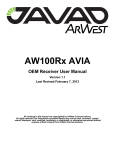
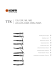
Kempact
251R, 253R, 323R, 181A, 251A, 253A, 323A
Operating manual
Käyttöohje
EN
FI
Bruksanvisning
SV
Bruksanvisning
NO
Brugsanvisning
DA
Gebrauchsanweisung
DE
Gebruiksaanwijzing
NL
Manuel d’utilisation
FR
Manual de instrucciones
ES
Instrukcja obsługi
PL
Инструкции по эксплуатации
RU
操作手册
ZH
Manual de utilização
PT
Manuale d’uso
IT
OPERATING MANUAL
English
CONTENTS
1.
Introduction.................................................................................. 3
1.1General. ............................................... . . . . . . . . . . . . . . . . . . . . . . . . . . . . . . . . . . . . . . . . . . . . . . . . . . . . . . . . . . . . . . . . . . . . . . . . . . . . . . . . . . . . . . . . 3
1.2 About Kempact RA. ........................ . . . . . . . . . . . . . . . . . . . . . . . . . . . . . . . . . . . . . . . . . . . . . . . . . . . . . . . . . . . . . . . . . . . . . . . . . . . . . . . . . . . . . . . . 3
1.2.1Properties. ................................. . . . . . . . . . . . . . . . . . . . . . . . . . . . . . . . . . . . . . . . . . . . . . . . . . . . . . . . . . . . . . . . . . . . . . . . . . . . . . . . . . . . . . . . . 3
1.2.2 About welding. ......................... . . . . . . . . . . . . . . . . . . . . . . . . . . . . . . . . . . . . . . . . . . . . . . . . . . . . . . . . . . . . . . . . . . . . . . . . . . . . . . . . . . . . . . . . 4
2.Preparations.................................................................................. 4
2.1Unpacking. ......................................... . . . . . . . . . . . . . . . . . . . . . . . . . . . . . . . . . . . . . . . . . . . . . . . . . . . . . . . . . . . . . . . . . . . . . . . . . . . . . . . . . . . . . . . . 4
2.2 Positioning and location of the machine. . . . . . . . . . . . . . . . . . . . . . . . . . . . . . . . . . . . . . . . . . . . . . . . . . . . . . . . . . . . . . . . . . . . . . . 4
2.3 Distribution network...................... . . . . . . . . . . . . . . . . . . . . . . . . . . . . . . . . . . . . . . . . . . . . . . . . . . . . . . . . . . . . . . . . . . . . . . . . . . . . . . . . . . . . . . . . 5
2.4 Serial number.................................... . . . . . . . . . . . . . . . . . . . . . . . . . . . . . . . . . . . . . . . . . . . . . . . . . . . . . . . . . . . . . . . . . . . . . . . . . . . . . . . . . . . . . . . . 6
3.
Machine introduction.................................................................. 6
4.
Before you start using the unit.................................................. 10
3.1 General view of the machine. ..... . . . . . . . . . . . . . . . . . . . . . . . . . . . . . . . . . . . . . . . . . . . . . . . . . . . . . . . . . . . . . . . . . . . . . . . . . . . . . . . . . . . . . . . . 6
3.2 Cable connections. ......................... . . . . . . . . . . . . . . . . . . . . . . . . . . . . . . . . . . . . . . . . . . . . . . . . . . . . . . . . . . . . . . . . . . . . . . . . . . . . . . . . . . . . . . . . 7
EN
4.1
4.2
4.3
4.4
4.5
4.6
4.7
4.8
4.9
Installing filler wire.......................... . . . . . . . . . . . . . . . . . . . . . . . . . . . . . . . . . . . . . . . . . . . . . . . . . . . . . . . . . . . . . . . . . . . . . . . . . . . . . . . . . . . . . . 10
Mounting and locking of filler wire spool.. . . . . . . . . . . . . . . . . . . . . . . . . . . . . . . . . . . . . . . . . . . . . . . . . . . . . . . . . . . . . . . . . . . 10
Setting the spool brake force...... . . . . . . . . . . . . . . . . . . . . . . . . . . . . . . . . . . . . . . . . . . . . . . . . . . . . . . . . . . . . . . . . . . . . . . . . . . . . . . . . . . . . . . 11
Loading the welding wire to feed mechanism. . . . . . . . . . . . . . . . . . . . . . . . . . . . . . . . . . . . . . . . . . . . . . . . . . . . . . . . . . 11
Welding gun. ..................................... . . . . . . . . . . . . . . . . . . . . . . . . . . . . . . . . . . . . . . . . . . . . . . . . . . . . . . . . . . . . . . . . . . . . . . . . . . . . . . . . . . . . . . 12
Setting the pressure of the feed rolls.. . . . . . . . . . . . . . . . . . . . . . . . . . . . . . . . . . . . . . . . . . . . . . . . . . . . . . . . . . . . . . . . . . . . . . . . . . . . 13
Wire guide tubes and feed rolls. . . . . . . . . . . . . . . . . . . . . . . . . . . . . . . . . . . . . . . . . . . . . . . . . . . . . . . . . . . . . . . . . . . . . . . . . . . . . . . . . . . . . . . 14
Changing the feed rolls. . ............... . . . . . . . . . . . . . . . . . . . . . . . . . . . . . . . . . . . . . . . . . . . . . . . . . . . . . . . . . . . . . . . . . . . . . . . . . . . . . . . . . . . . . . 16
Reversing polarity. .......................... . . . . . . . . . . . . . . . . . . . . . . . . . . . . . . . . . . . . . . . . . . . . . . . . . . . . . . . . . . . . . . . . . . . . . . . . . . . . . . . . . . . . . . 17
4.9.1 Dusty work environments........ . . . . . . . . . . . . . . . . . . . . . . . . . . . . . . . . . . . . . . . . . . . . . . . . . . . . . . . . . . . . . . . . . . . . . . . . . . . . . . . . . . . . . . 17
5.
Using control panels................................................................... 18
6.
MIG/MAG welding...................................................................... 24
5.1 Regular control panel. ................... . . . . . . . . . . . . . . . . . . . . . . . . . . . . . . . . . . . . . . . . . . . . . . . . . . . . . . . . . . . . . . . . . . . . . . . . . . . . . . . . . . . . . . 18
5.2 Adaptive control panel.................. . . . . . . . . . . . . . . . . . . . . . . . . . . . . . . . . . . . . . . . . . . . . . . . . . . . . . . . . . . . . . . . . . . . . . . . . . . . . . . . . . . . . . . 20
5.3 Parameter guides. ........................... . . . . . . . . . . . . . . . . . . . . . . . . . . . . . . . . . . . . . . . . . . . . . . . . . . . . . . . . . . . . . . . . . . . . . . . . . . . . . . . . . . . . . . 24
6.1 HOT SPOT function. ........................ . . . . . . . . . . . . . . . . . . . . . . . . . . . . . . . . . . . . . . . . . . . . . . . . . . . . . . . . . . . . . . . . . . . . . . . . . . . . . . . . . . . . . . 26
7.Maintenance............................................................................... 27
7.1 Daily maintenance. ......................... . . . . . . . . . . . . . . . . . . . . . . . . . . . . . . . . . . . . . . . . . . . . . . . . . . . . . . . . . . . . . . . . . . . . . . . . . . . . . . . . . . . . . . 27
7.2 Gun spare parts. ............................... . . . . . . . . . . . . . . . . . . . . . . . . . . . . . . . . . . . . . . . . . . . . . . . . . . . . . . . . . . . . . . . . . . . . . . . . . . . . . . . . . . . . . . 28
7.3Troubleshooting. ............................. . . . . . . . . . . . . . . . . . . . . . . . . . . . . . . . . . . . . . . . . . . . . . . . . . . . . . . . . . . . . . . . . . . . . . . . . . . . . . . . . . . . . . . 33
7.4Storage. ............................................... . . . . . . . . . . . . . . . . . . . . . . . . . . . . . . . . . . . . . . . . . . . . . . . . . . . . . . . . . . . . . . . . . . . . . . . . . . . . . . . . . . . . . . 34
7.5 Disposal of the machine............... . . . . . . . . . . . . . . . . . . . . . . . . . . . . . . . . . . . . . . . . . . . . . . . . . . . . . . . . . . . . . . . . . . . . . . . . . . . . . . . . . . . . . . 34
8. Error codes.................................................................................. 34
9. Ordering codes........................................................................... 35
10. Technical data............................................................................. 36
2
Kempact 251R, 253R, 323R, 181A, 251A, 253A, 323A
1.
INTRODUCTION
1.1 General
Congratulations on choosing Kempact RA welding equipment. Used correctly, Kemppi
products can significantly increase the productivity of your welding, and provide years of
economical service.
This operating manual contains important information on the use, maintenance and safety of
your Kemppi product. The technical specifications of the equipment can be found at the end
of the manual.
Please read the manual carefully before using the equipment for the first time. For your
own safety and that of your working environment, pay particular attention to the safety
instructions in the manual.
For more information on Kemppi products, contact Kemppi Oy, consult an authorised Kemppi
dealer, or visit the Kemppi web site at www.kemppi.com.
For Kemppi’s standard safety instructions and warranty terms and conditions, please visit our
web site at www.kemppi.com.
The specifications presented in this manual are subject to change without prior notice.
NOTE! Items in the manual that require particular attention in order to minimise damage and
EN
personal harm are indicated with this symbol. Read these sections carefully and follow their
instructions.
Disclaimer
While every effort has been made to ensure that the information contained in this guide
is accurate and complete, no liability can be accepted for any errors or omissions. Kemppi
reserves the right to change the specification of the product described at any time without
prior notice. Do not copy, record, reproduce or transmit the contents of this guide without
prior permission from Kemppi.
1.2 About Kempact RA
Kempact RA MIG/MAG welding machines are designed for professional industrial use. Before
use or doing any maintenance work on the machine, read the operating manual and keep it
for further reference.
Welding and earth return cables are supplied in the delivery package, including gun, earth
clamp and connections.
1.2.1 Properties
Kempact RA family sets new standards for the compact MIG/MAG equipment class and offers
many innovative features, designed to make welding more accurate and productive.
All models are suitable for welding a wide range of filler wire materials, including Fe, FCAW,
MCAW and MIG brazing. Kempact Adaptive models include a memory function for saving
frequently used weld settings. They also feature automatic power regulation, adjusted
through selection of plate thickness and weld profile.
All Kempact RA models feature a large and clear orange backlit LCD display for easy and fast
reference of parameter settings. All models include stepless control of voltage and wire feed
speed, spot and cycle arc timer, and 2T/4T gun switch selection, WireLine™ maintenance
alert indicator, Brights™ cabinet lighting, GasMate™ chassis design and HOT SPOT carbon arc
function.
© Kemppi Oy / 1135
3
1.2.2 About welding
In addition to the welding machine, welding outcome is influenced by the work piece to be
welded, welding technique and the welding environment. Therefore, recommendations in this
manual must be followed.
During welding, an electric welding circuit is created between the filler wire and the welded
piece. On delivery, the welding gun euro connector is connected to the positive pole. The
terminals are located inside the wire feed case door and should not be changed unless you
intend to run a filler wire that is directed to be used in reverse polarity, electrode negative.
When a filler wire is loaded to the machine and the gun trigger is pressed, the wire feed
mechanism drives the filler wire through the wire liner to the contact tip mounted in the
welding gun. The earth return socket on the back of the machine is set as the negative
terminal, and when connected to the workpiece via the earth return lead, it completes the
welding circuit.
When the filler wire touches the work piece, a short circuit occurs, forming the needed closed
electrical circuit. A welding arc is formed and welding commences. Unrestricted current flow
is possible only when the earth return clamp is properly attached to the workpiece and the
fixing point of the clamp to the workpiece is clean, and free from paint and rust.
EN
2.
PREPARATIONS
NOTE! Please read the separate safety instruction booklet provided before you commence welding.
Pay particular attention to the risks associated with fire and explosion.
2.1 Unpacking
When the machine leaves the factory, the wire drive system and gun it is set for use with
ferrous filler wire (181/251 models WHITE 0.8 wire feed rolls and 253/323 models RED 1.0
wire feed rolls). If you wish to use an alternative thickness filler wire or type, make sure that
you select appropriate feed rolls/groove size, welding gun contact tip and gun liner, and also
ensure that the machine polarity is correctly set for the material filler type used.
If using aluminium or stainless steel filler wire, we recommend you change the wire liner to a
Kemppi plastic type, which is better suited for the material.
Before using the equipment, always make sure it was not damaged during transportation.
Also check that you have received what you ordered and that there are instructions for it.
The packaging material of the products is suitable for recycling.
Environment
The machine is suitable for both indoor and outdoor use, but it should be protected from rain
and sunshine. Store the machine in a dry and clean environment and protect it from sand and
dust during use and storage. The recommended operating temperature range is –20…+40 °C.
Place the machine in such a way that it does not come in contact with hot surfaces, sparks and
spatters. Make sure the air flow into the machine is unrestricted.
2.2 Positioning and location of the machine
Place the machine on a firm, dry and level surface. Where possible, do not allow dust or other
impurities to enter the machines cooling air flow.
Notes for positioning the machine
• The surface inclination should not exceed 15 degrees.
• Ensure the free circulation of the cooling air. There must be at least 20 cm of free space
around the machine for cooling air to circulate.
• Protect the machine against heavy rain and direct sunshine.
NOTE! The machine should not be operated in the rain as the protection class of the machine,
IP23S, allows for outside preserving and storage only.
NOTE! Never use a wet welding machine.
4
Kempact 251R, 253R, 323R, 181A, 251A, 253A, 323A
NOTE! When locating and siting the machine prior to and during operation, it is important to
ensure that the metal chassis of the machine does not come into contact with the welding circuit,
and/or surfaces so connected.
EN
NOTE! Never aim metallic grinding spray/sparks towards the equipment.
2.3 Distribution network
All regular electrical devices without special circuits generate harmonic currents into
distribution network. High rates of harmonic current may cause losses and disturbance to
some equipment.
Kempact 181A, 251R, 251A:
Equipment complying with IEC 61000-3-12
Kempact 253R, 253A:
This equipment complies with IEC 61000-3-12 provided that the short-circuit power Ssc
is greater than or equal to 2.7 MVA at the interface point between the user’s supply and
the public supply network. It is the responsibility of the installer or user of the equipment
to ensure, by consultation with the distribution network operator if necessary, that the
equipment is connected only to a supply with a short-circuit power Ssc greater than or equal
to 2.7 MVA.
Kempact 323R, 323A:
This equipment complies with IEC 61000-3-12 provided that the short-circuit power Ssc
is greater than or equal to 2.1 MVA at the interface point between the user’s supply and
the public supply network. It is the responsibility of the installer or user of the equipment
to ensure, by consultation with the distribution network operator if necessary, that the
equipment is connected only to a supply with a short-circuit power Ssc greater than or equal
to 2.1 MVA.
Kempact 251 MVU:
This equipment complies with IEC 61000-3-12 provided that the short-circuit power Ssc
is greater than or equal to 1.1 MVA at the interface point between the user’s supply and
the public supply network. It is the responsibility of the installer or user of the equipment
to ensure, by consultation with the distribution network operator if necessary, that the
equipment is connected only to a supply with a short-circuit power Ssc greater than or equal
to 1.1 MVA.
© Kemppi Oy / 1135
5
Kempact 323 MVU:
This equipment complies with IEC 61000-3-12 provided that the short-circuit power Ssc
is greater than or equal to 1.5 MVA at the interface point between the user’s supply and
the public supply network. It is the responsibility of the installer or user of the equipment
to ensure, by consultation with the distribution network operator if necessary, that the
equipment is connected only to a supply with a short-circuit power Ssc greater than or equal
to 1.5 MVA.
2.4 Serial number
The serial number of the unit is marked on the rating plate. The serial number makes it
possible to trace product manufacturing series. You might need the serial number when
placing spare parts orders or when planning maintenance.
3.
EN
MACHINE INTRODUCTION
3.1 General view of the machine
1.
2.
3.
4.
5.
FE 32
1.
2.
3.
4.
5.
6
Supply voltage cable
Main switch
Shielding gas hose connector
Welding gun and cable
Earth return clamp and cable
Kempact 251R, 253R, 323R, 181A, 251A, 253A, 323A
3.2 Cable connections
Connection to the mains
Kempact RA models are available in either 1-phase 230 V, 3-phase 400 V, or multi-voltage
units. Machines supplied with a mains power cable are not equipped with a plug, so you must
select and fit a suitable mains plug before you use the machine for the first time.
Check that the mains cable complies with the local electrical regulations and replace the cable
if necessary. See ’Technical data’.
EN
NOTE! The mains cable or mains plug may be installed or replaced only by an electrical contractor
or installer authorised to perform such operations.
Welding gun
Kempact RA welding machines are supplied with Kemppi FE range welding guns as standard.
These guns are designed for industrial applications and if used and maintained correctly will
provide productive and reliable service.
NOTE! The gun is set at the factory for use with ferrous filler wires. Should you wish to use the gun
with an alterative filler wire size or type, please select the appropriate contact tip and wire liner.
© Kemppi Oy / 1135
7
Shielding gas
4.
20
15
10
2.
3.
5
l/min
1.
EN
Shielding gas is used for replacing air around the welding arc. For steel wires, use CO₂ (carbon
dioxide) or a mixture of Ar (argon) and CO₂ for shielding gas. Welding performance will be
improved when using mixed gas products. For stainless steel filler wires, use a mixture of Ar
and CO₂ (2 %), and for aluminium and CuSi filler wires, use pure argon. The required flow rate
of the shielding gas is determined by the thickness of the welded sheet and the used welding
power. Alternative gas mixtures are available. Contact your gas supplier for further advice.
The machine is delivered with a 1.5 m gas hose. Connect the gas hose to the machine’s male
connector at the back of the machine. Connect the other end of the gas hose to the gas
cylinder via a suitable and approved single stage regulator valve, where outlet flow rates can
be adjusted.
NOTE! Never attempt to connect directly to a compressed gas cylinder. Always use an approved
and tested regulator and flow meter.
Connecting the gas hose to a typical welding regulator control valve
1. Connect the hose to the welding machine
2. Open the regulator valve of the gas cylinder
3. Measure the gas flow
4. Adjust the flow with the adjustment knob (12–18 lpm)
NOTE! Use a suitable shielding gas for the welding application. Always secure the gas cylinder in
an upright position with either a specially made wall rack or the Kempact RA GasMate chassis,
securing the cylinder in place with the webbing and metal buckles provided. Always close the
cylinder valve after welding.
8
Kempact 251R, 253R, 323R, 181A, 251A, 253A, 323A
Moving the machine and gas cylinder
EN
The Kempact RA is designed to provide safe gas cylinder storage and movement in
satisfactory workshop conditions. The floor surface should be sound, level and free from
obstructions. These notes must be followed and an adequate risk assessment completed prior
to use of the equipment. Cylinder size and weight vary and therefore affect the total weight
and balance of equipment movement.
To move the machine and a small cylinder:
1. Load and secure the gas cylinder with straps provided.
2. Grip the machine handles and place one foot to the foot base plate, located in front of
the air intake grill. Press your foot firmly downwards and pull back the machine at the
same time, so lifting the machine and gas cylinder to a position for movement.
To move the machine and a large cylinder:
1. Load and secure the gas cylinder with straps provided.
2. With one hand, firmly grip the top of the cylinder and with the other hand grip one of
the machine handles.
3. Place one foot to the foot base plate, located in front of the air intake grill. Press your foot
firmly downwards and pull back the machine at the same time, so lifting the machine
and gas cylinder to a position for movement.
Additional safety notes:
NOTE! In both cases listed above, you will quickly feel the fulcrum point, mechanical advantage
and the point of balance. You are now ready to move your machine and gas cylinder to a new
location. However, caution should be observed at all times when moving heavy equipment and
local safety conditions and laws must be respected.
NOTE! Be careful when lowering the cylinder to its resting position. Whilst maintaining a firm grip,
ensure that you keep your back straight and extend your arms. Maintain firm pressure to the foot
base plate and slowly lower the machine and cylinder to its resting position. You will feel the weight
increase as you move forwards over the point of balance. Ensure you keep a firm grip and your
weight as far back as possible, as you lower the cylinder and machine chassis carefully to the floor.
NOTE! The chassis is designed to provide stability in the upright position, when loaded with or
without a gas cylinder. Reasonable effort is required to raise and lower the machine and cylinder to
a position of movement. If you are light in weight or in any way unsure about moving the machine
and cylinder, you should consider an alternative method or process. A local Health and Safety audit
and risk assessment may be necessary before heavy or new equipment is taken into use, including
the use for carrying or transporting compressed shielding gas cylinders.
© Kemppi Oy / 1135
9
NOTE! In all cases the chassis design is not recommended for lifting its weight clear of the
ground by the handles or any other means, with or without a gas cylinder loaded in place. When
transporting the machine between sites, welding gas cylinders must be removed from the chassis,
secured and transported by other means.
4.
BEFORE YOU START USING THE UNIT
4.1 Installing filler wire
EN
Kempact RA is designed for 300 mm wire spools and the following filler wire types:
• solid wires
• flux-cored wires
• self-shielded flux-cored wires
• stainless steel wires
• aluminium wires
• brazing wires
When choosing appropriate filler materials, remember that the wire must have approximately
the same melting point as the base material to be welded. MIG brazing process is an exception
to this rule.
NOTE! When changing the filler wire, always check that the feed rolls, their groove shape and size
and the wire liner inside the welding gun cable are suitable for the wire you are using. Also check
that you are using the correct polarity for the filler wire.
4.2 Mounting and locking of filler wire spool
1.
2.
3.
To mount the wire spool:
1. Turn the locking knob of the spool holder so that the locking clips are opened (1).
2. Check the rotating direction of the wire spool and push the spool into its place so that it
rotates in the right direction (2).
3. Turn the locking knob of the spool holder to close the locking clips (3).
NOTE! Check that the filler wire spool is correctly mounted and locked into position. Ensure the
spool is not damaged or deformed in such a way that it can rub or chaff against the internal
surface of the wire feed unit chassis or door. This may result in increased drag, impacting on weld
quality. This may also result in long term wire feed unit damage, rendering the unit unserviceable
or unsafe to use.
10
Kempact 251R, 253R, 323R, 181A, 251A, 253A, 323A
4.3 Setting the spool brake force
To prevent the filler wire from uncoiling on overrun following use at high feed speeds, you can
change the brake force of the welding spool. Adjust the spool brake force through the hole in
the spool locking mechanism. Increase the force by turning the screw clockwise and decrease
it by turning it anticlockwise.
NOTE! Do not over tighten and reduce the pressure for light filler wire types.
4.4 Loading the welding wire to feed mechanism
EN
GT02DuraTorque
NOTE! Always ensure that ALL wire guide tubes are correctly selected and installed before
connecting the welding gun.
1. Release the pressure lever(s) and open the pressure arm(s) carrying the top wire feed roll,
lifting clear on its pivot.
2. Draw some loose filler wire from the spool and carefully push it through the liner and
bronze guide at the back of the wire feed mechanism. Push the filler wire over the feed
roll groove and through the wire guide(s) tubes and Euro connector block, exposing
about 150 mm of filler wire from the front of the machine.
3. Close the top feed roll(s) lever(s) over the filler wire and close the pressure arm(s).
© Kemppi Oy / 1135
11
4.
Cut away any deformed filler wire section and dress the sharp wire tip.
5.
6.
Connect the welding gun and tighten the collar.
Press the welding gun trigger and allow the filler wire to feed through the gun cable to
the contact tip.
Check once again that the filler wire is still properly seated in the grooves of both top and
bottom feed rolls.
4.5 Welding gun
EN
Connect the welding gun connector to the Euro adapter socket located below the wire feed
mechanism and hand tighten only. Do not over tighten the gun collar.
NOTE! Remember to remove the sharp cut tip of the filler wire before loading the wire to the
welding gun, so preventing damage to the liner inside the welding gun cable. This is particularly
important for soft filler wires such as aluminium. It will also improve feed quality and increase the
service life of your gun liner.
12
Kempact 251R, 253R, 323R, 181A, 251A, 253A, 323A
4.6 Setting the pressure of the feed rolls
To ensure the filler wire runs smoothly into the welding gun wire liner you should adjust the
pressure of the feed rolls of the wire drive mechanism.
Turn the orange coloured pressure adjustment knob(s) in a clockwise direction to increase the
pressure applied to the welding filler wire, and anticlockwise to decrease it.
NOTE! Periodically remove and clean the short wire spiral located at the back of the wire feed
mechanism. See item D.
EN
There is a graduation scale marked on the pressure arm above or below the orange
adjustment knob, depending on the Kempact RA used. For models fitted with the two roll
GT02 wire drive system, the more pressure applied, the greater the number of graduation
marks visible. For models fitted with the four roll DuraTorque wire drive system, the more
pressure applied, the fewer number of graduation marks visible.
For hard steel and stainless steel filler wires make sure there is sufficient pressure applied,
so avoiding filler wire slippage in the feed rolls.
NOTE! Too much wire feed roll pressure may flatten the filler wire, damage its coating, increase
friction and result in the filler wire sticking in the welding gun liner or contact tip. Also excessive
pressure will result in increased wear to wire drive roll bearings, reducing their life.
© Kemppi Oy / 1135
13
4.7 Wire guide tubes and feed rolls
Wire guide tubes
A = front tube
B= centre tube
C = rear tube
D = wire spiral guide
GT 02: models 251R, 181A, 251A
Ss, Al, Fe, MC, FC
ø 0.6–1.6mm
D
W006410,
ø 2.5/125mm, steel
ø 2.5/97mm, W006164, plastic
ø 2.0mm, W006019, brass
A
C
C
A
D
EN
DuraTorque: models 253R, 323R, 253A, 323A
Ss, Al, Fe, MC, FC ø 0.6–1.6mm
ø 2.5/75mm,
W006369, plastic
ø 2.5/33mm,
W000956, plastic
Fe, MC, FC
ø 0.6–0.8mm
ø 1.5/75mm,
W006421, steel
ø 2.0/33mm,
W001435, steel
ø 1.0–1.6mm
ø 2.0/75mm,
W006422, steel
D
W006410,
ø 2.5/125mm, steel
A
C
B
A
14
ø 2.0mm,
W005784, brass
Kempact 251R, 253R, 323R, 181A, 251A, 253A, 323A
B
C
D
Removing front tube
Release pressure tension arm. Push the front tube out of its housing with a piece of filler wire.
EN
Wire feed rolls
NOTE! Orange part code colour denotes standard delivery specification.
GT 02 and DuraTorque
Fe, Ss, Al, V-groove
Fe, FC, MC,knurled, V-groove
Fe, FC, MC, Ss, Al,U-groove
ø mm
driving
pressing
0.6
W001045
W001046
0.8/0.9
W001047
W001048
(GT 02)
1.0
W000675
W000676
(DuraTorque)
1.2
W000960
W000961
1.0
W001057
W001058
1.2
W001059
W001060
1.0
W001067
W001068
1.2
W001069
W001070
For aluminium filler wires select the correct feed roll type from the chart supplied and adjust
for the minimum pressure necessary for reliable filler wire drive without deformation of the
wire itself.
For flux-cored filler wires select a knurled feed roll to achieve better wire grip.
NOTE! Slight slippage is recommended in the case of aluminium filler wires. This ensures that the
soft wire is not deformed and flattened and that the feed rolls skid over the soft wire if it stops when
passing through the gun liner or contact tip.
For aluminium and stainless steel filler wires, always use Kemppi DL Teflon gun liners.
These liners are especially developed by Kemppi and significantly reduce friction losses, so
improving welding performance and quality.
© Kemppi Oy / 1135
15
4.8 Changing the feed rolls
Kempact RA machines are factory fitted with wire feed rolls as part of the delivery packages.
However, it may be necessary to select alternative feed rolls to suit different filler wire sizes
used. So you may occasionally need to replace the feed rolls. Kemppi feed rolls and gun liners
are colour-coded in order to make identification easy.
1.
2.
EN
3.
4.
5.
To change the feed rolls:
1. Pull and release the pressure tension arm.
2. Lift the upper feed roll on its pivot to the maximum open position.
3. Pull out mounting pin of the upper feed pressure roll and replace the roll with a new one.
4. Open the locking screw of the lower feed roll and replace the roll with a new one.
5. Return the upper pressure feed roll to its down position and replace the pressure tension
arm.
6. Adjust the pressure tension as instructed in the earlier section.
16
Kempact 251R, 253R, 323R, 181A, 251A, 253A, 323A
4.9 Reversing polarity
Some filler wires are recommended to be welded with the gun in the minus pole (–), so the
polarity should be reversed. Check the recommended polarity from the filler wire package.
1.
2.
3.
4.
5.
6.
Disconnect the machine from the mains.
Expose the terminal connections by bending the protective rubber covers away from the
terminal.
Remove the terminal tightening nuts and washers. Note the correct order of the
washers!
Interchange the cables.
Install the washers in place and re-tightening the securing nuts.
Replace the rubber terminal covers. The rubber covers must always protect the terminals
during use.
EN
4.9.1 Dusty work environments
If the working environment frequently carries airborne metallic dust particles due to
fabrication practices, it is recommended that you install a filter casette to the machine.
Particle filter cassette's ordering code: W005852.
Fitting the particle filter cassette provides additional protection to your welding machine and
lengthens its service intervals.
Filter maintenance
Once fitted, the filter should be removed, checked and cleaned with dry compressed air
weekly. Every six months, wash the filter in a solution of warm soapy water. Allow to dry
thoroughly before replacing.
© Kemppi Oy / 1135
17
5.
USING CONTROL PANELS
5.1 Regular control panel
4.
5.
SPOT /
CYCLE
GAS
6.
2T / 4T
7.
MIG
HOT SPOT
4T
MANUAL
9.
POST GAS
8.
10.
V
m
min
U
W006169
DYNAMICS
EN
1.
2.
3.
Models featuring the regular (R) control panel offer the following control functions and
features.
1. Control knob for welding dynamics
2. Control knob for wire feed speed
3. Control knob for welding voltage
4. Shielding gas button
5. Timer button for spot welding and cycle arc welding
6. 2T/4T gun switch latching button
7. Selection for MIG/MAG or HOT SPOT function
8. Parameter display
9. Overheating indicator
10. WireLine service indicator
1. Control knob for welding dynamics
Dynamics function controls the rate of rise of current when the filler wire is in short circuit
with the welding plate. This control adjustment is necessary due to the alternative welding
parameters, materials, wire sizes, gas types and current values used.
The welding dynamics scale is –9 to +9. Negative values make the rise of current slower, which
results in a hotter and more fluid weld characteristic. Positive values make the rise of current
faster, which results in a colder welding condition. This can result in more spatter during
welding depending on the filler wire size and type used.
How to find the optimal dynamics setting?
Start by setting ‘0’ and make a test weld after selecting the correct wire feed speed and
voltage values. Fine tune the welding arc by trying different values in the negative (-) and
positive (+) sides of the dynamics scale.
2. Control knob for wire feed speed
This control knob increases and reduces the speed of filler wire delivery to the welding arc.
The scale is regulated in meters per minute. There is also a graphical display bar indicating the
proportion of motor speed selected.
18
Kempact 251R, 253R, 323R, 181A, 251A, 253A, 323A
3. Control knob for welding voltage
This control knob increases and reduces the available output voltage of the machine to the
welding arc. The scale is regulated in volts and is also supported by a graphical display bar that
indicates the proportion of the available output voltage selected.
4. Shielding gas button
GAS
This button sets the machine's dynamics range for either mixed (Ar/C0₂) or carbon dioxide
(C0₂) shielding gas. A single press of the button changes the set-up for the intended gas type.
The selected shielding gas type is shown in the LCD display panel. If using argon shielding gas
for aluminium or CuSi MIG brazing filler wires, use the mixed gas setting (Ar/C0₂).
5. Timer button for spot and cycle arc welding
SPOT /
CYCLE
The spot and cycle arc timer offers two modes of function. By pressing and selecting the SPOT
timer, you regulate the time duration for one single ‘SPOT’ welding cycle from either 0.1 to 9.9
seconds of arc time. By selecting the ‘CYCLE' arc timer you regulate the machine to a repeating
cycle of arc time and pause time. The pause time offered is 0.1 to 3 seconds. Select function by
depressing button 4. Regulation and adjustment of SPOT and CYCLE arc values are adjusted
by the voltage control (item 3). Function selection is confirmed by either one dot (SPOT TIME)
or dash line (CYCLE TIME) under the word 'Timer’ in the display.
EN
6. 2T/4T gun switch latching button
2T / 4T
This button offers you two modes of welding gun functions. The selected mode is indicated as
either 2T or 4T in the display.
• In 2T mode the welding arc is started by a single press and hold of the welding gun
trigger. Welding continues whilst the trigger is held, and stops when the trigger is
released.
• In 4T mode the gun trigger is pressed and gas starts to flow. When the trigger is
released, the arc ignites. Welding continues until the trigger is pulled and released for a
second time. This mode is useful for long welding durations.
7. Selection for MIG/MAG or HOT SPOT welding function
MIG
HOT SPOT
This button switches the machine from standard MIG/MAG welding mode to a specialised
process function for localised spot heating and stress relieving for metal panels.
This function is normally used in the automotive industry and light sheet fabrication. To switch
between functions, press and hold the button for 5 seconds. See further information on HOT
SPOT function later in this manual.
8. Parameter display
The large illuminated parameter display is designed to provide excellent visibility of welding
values and machine settings in a variety of welding situations. The display is protected by a
polycarbonate lens fitted into the control panel housing.
© Kemppi Oy / 1135
19
9. Overheating indicator
Under normal working conditions the overheating indicator is not visible. However, should
the machine exceed its working duty cycle, welding will cease and the thermometer symbol
will illuminate indicating that the machine has overheated. The cooling fans of the machine
will continue to operate. When normal operating temperature is regained, the machine will
reset and welding can continue. The overheating indicator will no longer be visible.
10. WireLine service indicator
Under normal working conditions, the WireLine service indicator is not visible. However, if
the welding gun contact tip or liner becomes dirty and blocked or the wire feed mechanism
needs routine maintenance or the friction plates in the spool brake need adjustment or
maintenance, the Spanner service symbol will illuminate indicating that maintenance is
required. Welding is not prevented when the WireLine service symbol is active.
EN
5.2 Adaptive control panel
11.
15.
MATERIAL
MEMORY
16.
WIRE Ø
A /
13.
14.
GAS
CRATER
FILL
4.
SPOT /
CYCLE
5.
2T / 4T
POST GAS
BRAZING
1
7.
12.
mm
Ar +
6.
MODE
HOT SPOT
2T
CRATER
FILL ON
AUTOMATIC
8.
9.
POST GAS
2
mm
3
S
SAVE
U
POWER
W006149
DYNAMICS
10.
V
m
min
4
1.
2.
3.
Models featuring the adaptive (A) control panel offer the following control functions.
1. Dynamics control
2. Control knob for wire feed speed or power (adaptive mode)
3. Control knob for voltage or arc length (adaptive mode)
4. Timer button for spot welding and cycle arc welding
5. Selection of 2T/4T gun operating mode
6. Selection for MANUAL, AUTOMATIC or HOT SPOT function
7. Parameter display
8. Overheating indicator
9. WireLine service indicator
10. Post gas symbol
11. Selection for materials type or display of amperes/wire feed speed (adaptive mode)
12. Selection for filler wire diameter (adaptive mode)
13. Selection for shielding gas or post gas function (adaptive mode)
14. Selection of crater fill function (adaptive mode)
15. Selection for memory function
16. Material thickness and weld shape display
20
Kempact 251R, 253R, 323R, 181A, 251A, 253A, 323A
1. Dynamics control
Dynamics function controls the rate of rise of current when the filler wire is in short circuit
with the welding plate. This control adjustment is necessary due to the alternative welding
parameters, materials, wire sizes, gas types and current values used.
The welding dynamics scale is –9 to +9. Negative values make the rise of current slower, which
results in a hotter and more fluid weld characteristic. Positive values make the rise of current
faster, which results in a colder welding condition. This can result in more spatter during
welding depending on the filler wire size and type used.
How to find the optimal dynamics setting?
Start by setting ‘0’ and make a test weld after selecting the correct wire feed speed and
voltage values. Fine tune the welding arc by trying different values in the negative (-) and
positive (+) sides of the dynamics scale.
2. Control knob for wire feed speed or power (adaptive mode)
This control knob increases and reduces the speed of filler wire delivery or power to the
welding arc. The scale is regulated in meters per minute or amperes. There is also a graphical
display bar indicating the proportion of motor speed or power selected.
3. Control knob for voltage or arc length (adaptive mode)
This control knob increases and reduces the available output voltage of the machine to the
welding arc. The scale is regulated in volts and is also supported by a graphical display bar that
indicates the proportion of the available output voltage selected.
In adaptive mode this control knob offers minor arc voltage adjustment for fine tuning the
welding arc.
EN
4. Timer button for spot welding and cycle arc welding
SPOT /
CYCLE
The spot and cycle arc timer offers two modes of function. By pressing and selecting the SPOT
timer, you regulate the time duration for one single ‘SPOT’ welding cycle from either 0.1 to 9.9
seconds of arc time. By selecting the ‘CYCLE' arc timer you regulate the machine to a repeating
cycle of arc time and pause time. The pause time offered is 0.1 to 3 seconds. Select function by
depressing button 4. Regulation and adjustment of SPOT and CYCLE arc values are adjusted
by the voltage control (item 3). Function selection is confirmed by either one dot (SPOT TIME)
or dash line (CYCLE TIME) under the word 'Timer’ in the display.
5. Selection of 2T/4T gun operating mode
2T / 4T
This button offers you two modes of welding gun functions. The selected mode is indicated as
either 2T or 4T in the display.
• In 2T mode the welding arc is started by a single press and hold of the welding gun
trigger. Welding continues whilst the trigger is held, and stops when the trigger is
released.
• In 4T mode the gun trigger is pressed and gas starts to flow. When the trigger is
released, the arc ignites. Welding continues unti the trigger is pulled and released for a
second time. This mode is useful for long welding durations.
© Kemppi Oy / 1135
21
6. Selection for MANUAL, AUTOMATIC or HOT SPOT function
MODE
HOT SPOT
This button switches the machine from standard MIG/MAG welding mode to a specialised
process function for localised spot heating and stress relieving for metal panels.
This function is normally used in the automotive industry and light sheet fabrication. To switch
between functions, press and hold the button for 5 seconds. See further information on HOT
SPOT function later in this manual.
7. Parameter display
The large illuminated parameter display is designed to provide excellent visibility of welding
values and machine settings in a variety of welding situations. The display is protected by a
polycarbonate lens fitted into the control panel housing.
8. Overheating indicator
EN
Under normal working conditions the overheating indicator is not visible. However, should
the machine exceed its working duty cycle, welding will cease and the thermometer symbol
will illuminate indicating that the machine has overheated. The cooling fans of the machine
will continue to operate. When normal operating temperature is regained, the machine will
reset and welding can continue. The overheating indicator will no longer be visible.
9. WireLine service indicator
Under normal working conditions, the WireLine service indicator is not visible. However, if
the welding gun contact tip or liner becomes dirty and blocked or the wire feed mechanism
needs routine maintenance or the friction plates in the spool brake need adjustment or
maintenance, the Spanner service symbol will illuminate indicating that maintenance is
required. Welding is not prevented when the WireLine service symbol is active.
10. Post gas symbol
POST GAS
This symbol indicates that the post gas function is active. Kempact Regular (R) models
have fixed post gas function, but in Kempact Adaptive (A) models the post gas time can be
changed through a long press of button 13. In both models, the words POST GAS on the
display identify that the function is active.
11. Selection for materials type or display of amperes/wire feed speed (adaptive mode)
MATERIAL
A /
When operating in adaptive mode and AUTOMATIC is selected from the mode selection
button 6, a selection of filler materials types is presented through short presses of button
11. Materials selection includes FE, BRAZING, FCAW, MCAW. When selecting a suitable filler
material, POWER regulation is achieved through POWER selection knob 2. A long press (5 secs)
of button 11 also switches the display from m/min to amperes.
22
Kempact 251R, 253R, 323R, 181A, 251A, 253A, 323A
12. Selection for filler wire diameter (adaptive mode)
WIRE Ø
When operating in adaptive mode and AUTOMATIC is selected from the mode selection
button 6, you can select from the filler wire diameter options. Following your materials
selection through button 11, press button 12 briefly to select the filler wire diameter. Not all
materials have alternative choices.
13. Selection for shielding gas or post gas function (adaptive mode)
GAS
POST GAS
When operating in adaptive mode and AUTOMATIC is selected from the mode selection
button 6, you can select from the shielding gas option for the filler material type set. Shielding
gas options are displayed with a short press of button 13. When operating in either MANUAL
or AUTOMATIC mode you can also select POST GAS function and make adjustments to the
POST GAS time value with adjustment knob 3. The POST GAS adjustment range is from 0.1
second to 3.0 seconds.
14. Selection of crater fill function (adaptive mode)
EN
CRATER
FILL
When operating in adaptive mode and AUTOMATIC is selected from the mode selection
button 6, you can select CRATER FILL function. CRATER FILL function activates a pre‐set slope
timer at the end of the welding cycle and operates in either 2T or 4T gun switch mode when
the off signal is given.
15. Selection for memory function
MEMORY
1
2
3
4
SAVE
When operating in either MANUAL or AUTOMATIC mode, you can store your welding
parameters using the MEMORY function. There are four MEMORY locations to choose from,
and you can store either MANUAL or AUTOMATIC welding setup in any channel location. To
store your welding settings, simply press and hold a MEMORY button for 5 seconds.
To recall the welding settings for future use, simple short press the MEMORY buttons. To
record new weld settings to a channel, repeat the long press sequence.
© Kemppi Oy / 1135
23
16. Material thickness and weld shape display
mm
When operating in adaptive mode and AUTOMATIC is selected from the mode selection
button 6, the material thickness and weld shape is displayed, based on your input selections
for plate thickness in mm and weld shape. Adjust these values though control knobs 2 and
3. As you adjust the power control (2), you will see the graphic indicating plate thickness
become thicker or thinner, and as you adjust the arc length control (3) you will see the weld
shape change from convex, flat and concave. Select the desired settings and you are ready to
weld.
5.3 Parameter guides
Fe 0.8 mm, 5 – 18 % CO₂/Ar
PlateThickness
WireFeedSpeed
SetVoltage
MeanCurrent
EN
mm
m/min
V
A
0.5
2
14.5
40
0.8
2.5
15
50
1
3.5
15.5
65
1.5
5
16
97
2
8
17
130
2.5
10
18
155
mm
m/min
V
A
0.7
1.4
15.0
40
1.5
3.2
17.5
100
2
4.5
18.4
150
3
6.5
21.4
180
4
8.5
23.8
200
5
11.0
28.8
240
mm
m/min
V
A
1
1.5
14.6
75
1.5
2.2
17.0
100
2
3.2
17.8
140
3
5.0
21.0
180
4
6.0
22.7
220
6
7.2
26.3
250
3
13
20
185
Fe 1.0 mm, 5 – 25% CO₂/Ar
Plate Thickness
Wire Feed Speed
Set Voltage
Mean Current
Fe 1.2 mm, 5 – 25% CO₂/Ar
Plate Thickness
Wire Feed Speed
Set Voltage
Mean Current
6.
MIG/MAG WELDING
NOTE! Welding fumes may be dangerous to your health. Ensure that there is ample ventilation
during welding! Never look at the arc without a face shield specifically designed for arc welding!
Protect yourself and your surrounding area from the arc and hot welding spatter!
NOTE! Always wear protective clothing, gloves, face and eye shields suitable for welding. It is
recommended that you make practice welds before you commence welding your main work piece.
NOTE! The work piece will be very hot. Protect yourself and others at all times.
You can start welding after you have made the necessary preparation described throughout
these instructions.
Providing you ensure that the equipment is correctly prepared and set for the material type
and joint to be welded, you will achieve exceptionally high quality welding results.
• Ensure that the correct filler wire type and size is selected for the work piece.
• Ensure that the correct wire liner and contact tip size is fitted to the welding gun.
• Ensure that the correct shielding gas type is connected and the flow rate adjusted before
welding starts.
24
Kempact 251R, 253R, 323R, 181A, 251A, 253A, 323A
• Ensure the earth return clamp is connected to the work piece
• Ensure that you are wearing the correct safety equipment before you start welding
– including: suitable welding clothing, the correct welding face shield with a suitable
shade welding lens, welding gloves and when necessary, a welding mask.
NOTE! Please read section 1.2.2 before proceeding further.
EN
FE 32
Having checked that the equipment is prepared in the correct way for the welding task ahead,
and that you are wearing the necessary protective equipment, you are ready to commence
welding.
MIG/MAG welding can be performed down hand, vertically and overhead: either right to left
(right handed operators) or left to right (left handed operators)
First, present the welding gun nozzle to a practice work piece. The gun nozzle should be
approximately 15 mm away from the surface of the work piece and weld joint. If welding a T
fillet joint, the gun should be held at an angle of approximately 45 degrees, bisecting the 90
degree joint at the midway point. Starting at the right hand side of the joint (right handed
operators only), lean the gun backwards slightly, so the gun nozzle is pointing forwards,
towards the centre of the work piece. This is called a 'pushing technique' and is suitable for
most applications.
Pull the welding gun trigger. The filler wire will move forward, and a short circuit will occur and
the arc will be established. Keeping the gun trigger depressed, the molten weld pool will start
to form. Begin to travel the gun forwards, in a controlled manner and travel speed. Providing
you have correctly set your equipment, the quality of your weld deposit is now determined by
your skill and technique.
The resulting weld deposit, width and shape, should be consistent in appearance and quality.
If you are welding too fast the weld bead may be too thin or even intermittent in appearance.
Try to slow your travel speed slightly and maintain an even approach to the joint. If you are
welding too slowly, you may find the weld deposit is too heavy, the weld piece overheats and
possibly burns a hole through the plate. All that may be required to ensure a successful result
here is an increase in forward travel speed, but you may also need to reduce the power setting
slightly, to achieve the desired result.
As with all craft skills – practice will make perfect! For more information, visit the Welding ABC
section in www.kemppi.com.
© Kemppi Oy / 1135
25
6.1 HOT SPOT function
NOTE! The HOT SPOT component kit is suitable for use with the FE 20/25 welding guns only.
Setting and function
1. Before using HOT SPOT function, release the pressure tension arms at the wire feed
mechanism.
2. Rotate the filler wire spool slowly clockwise, removing the filler wire away from the FE
welding gun contact tip and neck.
3. Fit the special HOT SPOT electrode adaptor and carbon electrode into the gun head as
shown.
9592106holder
4192160 carbon electrode
FE
25
EN
FE
25
4.
5.
Select HOT SPOT mode with the control panel button 6.
Select the required HOT SPOT power level. There are 4 power level options depending
on the machine type in use.
6. Place the carbon electrode to the work piece, fixing, or area requiring spot heating.
7. Pull the trigger to activate the HOT SPOT function. The electrode will quickly heat up and
depending on the power level set , will glow red hot.
8. When sufficient heating effect is reached, release the trigger and remove the electrode
from the work piece.
9. When HOT SPOT process is complete, press control panel button 6 to return the machine
to standard MIG/MAG mode.
10. When cool and safe to handle, remove the HOT SPOT carbon and holder, replacing the
standard FE welding gun parts ready to continue welding.
NOTE! HOT SPOT function is only possible in 2T gun trigger mode. If 4T selection is made, the
function will automatically revert to 2T operation.
26
Kempact 251R, 253R, 323R, 181A, 251A, 253A, 323A
7.
MAINTENANCE
NOTE! Be careful when handling electrical cables!
In maintaining the unit, take into consideration the rate of use and the environment it is
used in. When the unit is used properly and serviced regularly, you will avoid unnecessary
disturbances in use and production.
7.1 Daily maintenance
• Remove welding spatters from the welding gun’s tip and check the condition of the
parts. Change damaged parts to new ones immediately. Only use original Kemppi spare
parts.
• Change damaged insulation parts to new ones immediately.
• Check the tightness of the welding gun’s and earth return cable’s connections.
• Check condition of mains and welding cables and replace damaged cables.
• See that there is enough space around the unit for ventilation.
Service the wire feed mechanism at least every time the spool is changed.
• Check the wear of the feed roll groove and change the feed roll when necessary.
• Carefully clean the welding gun wire liner with dry compressed air.
NOTE! When using compressed air pistols, ensure you are wearing adequate safety equipment
including, suitable work clothing, gloves and eye protection. Never direct compressed air pistols or
the end of the liner at your skin, face or others in the vicinity.
EN
NOTE! Kempact RA models are fitted as standard with both over temperature and WireLine service
indicators (described earlier in the manual).
If the overheating indicator is displayed, this may be due to welding durations exceeding
the set duty cycle. The machine will reset after a cooling rest period. However, if the optional
cooling air intake filter is fitted to the machine, this may be contaminated, restricting cooling
airflow and require cleaning. See section 4.9.1.
If the WireLine service indicator is illuminated, this indicates that the wire delivery system is
not running efficiently. Checks, adjustment or cleaning is required to the spool hub friction
assembly, wire feed mechanism or gun/liner assembly. Welding is not prevented when the
WireLine service symbol is active, and is maintenance advice only.
© Kemppi Oy / 1135
27
7.2 Gun spare parts
NOTE! Orange part code colour denotes standard delivery specification.
FE 20: 6602003 (3.5 m), 6602004 (5.0 m)
C
Gas nozzle
(AxBxC)
A
9580101
60.5 x 18 x 14 mm, standard
958010101
60.5 x 18 x 14 mm, with insulating bush
(= 9580101 + 9591079)
4113470
60.5 x 18 x 14 mm, for spot welding
9580101E
60.5 x 20 x 14 mm, thick wall
B
Insulating bush
9591010
Contact tip (M6)
9876634
ø 0.6 mm
9876635
0.8 mm
9876633
0.9 mm
9876636
1.0 mm
9876637
1.2 mm
EN
28
Contact tip
adapter (M6)
9580173
Insulating ring
9591079
Locking spring
4275240
Neck
Wire liner
4153040
45°
4188573
ø 0.6–0.8 mm
3.5 m
W006453
0.9–1.2 mm
3.5 m
W006457
0.8–1.0 mm
Al/Ss
3.5 m
W006459
1.0–1.6 mm
Al/Ss
3.5 m
4188576
0.6–0.8 mm
W006454
0.9–1.2 mm
W006458
0.8–1.0 mm
Al/Ss
5m
W006460
1.0–1.6 mm
Al/Ss
5m
Kempact 251R, 253R, 323R, 181A, 251A, 253A, 323A
5m
5m
FE 25: 6602503 (3.5 m), 6602504 (5.0 m)
C
Gas nozzle
(A x B x C)
A
9580101
60.5 x 18 x 14 mm, standard
958010101
60.5 x 18 x 14 mm, with insulating bush
(= 9580101 + 9591079)
4113470
60.5 x 18 x 14 mm, for spot welding
9580101E
60.5 x 20 x 14 mm, thick wall
B
Insulating bush
9591010
Contact tip (M6)
9876634
ø 0.6 mm
9876635
0.8 mm
9876633
0.9 mm
9876636
1.0 mm
9876637
1.2 mm
Contact tip adapter (M6)
9580173
Insulating ring
9591079
Locking spring
4275240
Neck
Wire liner
4153040
© Kemppi Oy / 1135
EN
45°
4188573
ø 0.6–0.8 mm
3.5 m
W006453
0.9–1.2 mm
3.5 m
W006457
0.8–1.0 mm
Al/Ss
3.5 m
W006459
1.0–1.6 mm
Al/Ss
3.5 m
4188576
0.6–0.8 mm
5m
W006454
0.9–1.2 mm
5m
W006458
0.8–1.0 mm
Al/Ss
5m
W006460
1.0–1.6 mm
Al/Ss
5m
29
FE 27: 6602703 (3.5 m), 6602704 (5.0 m)
FE 32: 6603203 (3.5 m), 6603204 (5.0 m)
C
Gas nozzle
4295760
76 x 20 x 14 mm, standard / M8
4295760L
79 x 20 x 14 mm, long / M8
4295760C
76 x 20 x 12 mm, conical / M8
4294970
70 x 20 x 14 mm, standard / M6
9876634
ø 0.6 mm
9876635
0.8 mm
9876633
0.9 mm
9876636
1.0 mm
9876637
1.2 mm
9876639
1.6 mm
9580122
ø 0.8 mm
9580122A
ø 0.8 mm
9580121
0.9
9580121A
0.9
9580123
1.0
9580123A
1.0
9580124
1.2
9580124A
1.2
9580125
1.4
9580125A
1.4
9580126
1.6
9580126A
1.6
9580123ZR
1.0
CuCr1Zr
9580122SS 0.8
9580124ZR
1.2
CuCr1Zr
9580121SS 0.9
9580125ZR
1.4
CuCr1Zr
9580123SS 1.0
9580123AG
1.0
CuAg
9580124SS 1.2
9580124AG
1.2
CuAg
9580126SS 1.6
Contact tip
adapter
4294890
M6
4295740
M8
Gas diffuser
4294880
(A x B x C)
A
Contact tip
(M6)
B
(M8)
M8
M6
EN
4294880CER
Neck
Wire liner
30
3146780
50°
4188573
ø 0.6–0.8 mm
3.5 m
W006453
0.9–1.2 mm
3.5 m
W006455
1.4–1.6 mm
3.5 m
W006457
0.8–1.0 mm
Al/Ss
3.5 m
W006459
1.0–1.6 mm
Al/Ss
3.5 m
4188576
0.6–0.8 mm
5m
W006454
0.9–1.2 mm
5m
W006456
1.4–1.6 mm
5m
W006458
0.8–1.0 mm
Al/Ss
5m
W006460
1.0–1.6 mm
Al/Ss
5m
Kempact 251R, 253R, 323R, 181A, 251A, 253A, 323A
FE 35: 6603503 (3.5 m), 6603504 (5.0 m)
C
Gas nozzle
(AxBxC)
A
Insulating bush
B
SP004585
4300260
77 x 22 x 16 mm, standard
4300260L
80 x 22 x 16 mm, long
4300260C
77 x 22 x 13 mm, conical
4307050
77 x 22 x 16 mm, standard, spatter protection bush
4307020
Contact tip (M8) 9580122
SP600317
© Kemppi Oy / 1135
ø 0.8 mm
9580122A
ø 0.8 mm
9580121
0.9
9580121A
0.9
9580123
1.0
9580123A
1.0
9580124
1.2
9580124A
1.2
9580125
1.4
9580125A
1.4
9580126
1.6
9580126A
1.6
9580123ZR
1.0
CuCr1Zr
9580122SS 0.8
9580124ZR
1.2
CuCr1Zr
9580121SS 0.9
9580125ZR
1.4
CuCr1Zr
9580123SS 1.0
9580123AG
1.0
CuAg
9580124SS 1.2
9580124AG
1.2
CuAg
9580126SS 1.6
Contact tip
adapter
4295740
M8
Gas diffuser
W004390
Insulator
W004165
Neck
SP004585
50°
SP600317
50°, neck includes temperature protection spring as standard.
Wire liner
4188573
ø 0.6–0.8 mm
3.5 m
W006453
0.9–1.2 mm
3.5 m
W006455
1.4–1.6 mm
3.5 m
W006457
0.8–1.0 mm
Al/Ss
3.5 m
W006459
1.0–1.6 mm
Al/Ss
3.5 m
4188576
0.6–0.8 mm
5m
W006454
0.9–1.2 mm
5m
W006456
1.4–1.6 mm
W006458
0.8–1.0 mm
Al/Ss
5m
W006460
1.0–1.6 mm
Al/Ss
5m
EN
5m
31
FE 42: 6604203 (3.5 m), 6604204 (5.0 m)
C
Gas nozzle
(A x B x C)
A
B
4300380L
83 x 25 x 18 mm, long
4300380C
80 x 25 x 14 mm, conical
4307070
80 x 25 x 18 mm, standard, spatter protection bush
4308190
89.5 x 25x18 mm, special long
9580122
ø 0.8 mm
9580122A
ø 0.8 mm
9580121
0.9
9580121A
0.9
9580123
1.0
9580123A
1.0
9580124
1.2
9580124A
1.2
9580125
1.4
9580125A
1.4
9580126
1.6
9580126A
1.6
9580123ZR
1.0
CuCr1Zr
9580122SS 0.8
9580124ZR
1.2
CuCr1Zr
9580121SS 0.9
9580125ZR
1.4
CuCr1Zr
9580123SS 1.0
9580123AG
1.0
CuAg
9580124SS 1.2
9580124AG
1.2
CuAg
9580126SS 1.6
Contact tip
adapter
4304600
M8
Gas diffuser
W004505
Insulator
W004579
Neck
SP004578
50°
SP600316
50°, neck includes temperature protection spring as standard.
EN
SP600317
Wire liner
32
80 x 25 x 18 mm, standard
Insulating bush 4307030
Contact tip
(M8)
SP004585
4300380
4188573
ø 0.6–0.8 mm
3.5 m
W006453
0.9–1.2 mm
3.5 m
W006455
1.4–1.6 mm
3.5 m
W006457
0.8–1.0 mm
Al/Ss
3.5 m
W006459
1.0–1.6 mm
Al/Ss
3.5 m
4188576
0.6–0.8 mm
5m
W006454
0.9–1.2 mm
5m
W006456
1.4–1.6 mm
5m
W006458
0.8–1.0 mm
Al/Ss
5m
W006460
1.0–1.6 mm
Al/Ss
5m
Kempact 251R, 253R, 323R, 181A, 251A, 253A, 323A
7.3 Troubleshooting
Welding performance can be effected by a number of issues, including the welding gun and/
or other parts of the welding system. The following information will help you to check, identify
and rectify possible causes of welding malfunction.
NOTE! The problems listed and the possible causes are not definitive, but serve to suggest some
standard and typical situations that may present during normal use when using the MIG/MAG
process.
Dirty, poor quality weld?
• Check that spatter is not blocking the nozzle or contact tip adapter
• Check shielding gas supply
• Check and set gas flow rate
• Check gas type for application
• Check gun polarity. Example: Fe solid filler wire: Earth return socket should be connected to the - pole, wire feed/gun
connection to the + pole
• Check power supply – Phase down?
Variable welding performance?
• Check wire feed mechanism is correctly adjusted
• Check correct drive rolls are fitted
• Check wire spool/hub overrun tension is correctly adjusted
• Check gun liner is not blocked. Replace if necessary
• Check correct gun liner is fitted for the filler wire size and type
• Check contact tip for size, type and wear
• Check gun is not over heating for the application
• Check cable connections and earth return clamp
• Check welding parameter settings.
EN
Filler wire won’t feed?
• Check wire feed mechanism. Adjust as necessary
• Check welding gun switch function.
• Check euro gun connector is correctly fitted
• Check gun liner is not blocked
• Check contact tip, size, type, wear
• Check filler wire diameter for correct size
High spatter volume?
• Check welding parameter values
• Check inductance/dynamics values
• Check gas type and flow
• Check welding polarity and cable connections
• Check filler material selection
• Check filler wire delivery system
• Check power supply. Are all electrical phases present?
• Check that operator maintains correct technique/arc length/travel speed/gun angle
NOTE! Many of these checks may be carried out by the operator. However certain checks relating to
mains power must be completed by an authorised trained electrician.
© Kemppi Oy / 1135
33
7.4 Storage
Store the unit in a clean and dry place. Shield it from rain, and in temperatures exceeding
+25 °C from direct exposure to sun.
7.5 Disposal of the machine
Do not dispose of electrical equipment with normal waste!
In observance of European Directive 2002/96/EC on waste electrical and electronic
equipment, and its implementation in accordance with national law, electrical equipment
that has reached the end of its life must be collected separately and taken to an appropriate
environmentally responsible recycling facility.
The owner of the equipment is obliged to deliver a decommissioned unit to a regional
collection centre, per the instructions of local authorities or a Kemppi representative. By
applying this European Directive you will improve the environment and human health.
8.
EN
ERROR CODES
Error 2: Mains under voltage
The machine has detected mains under voltage that disturbs welding. Check the quality of the
supply network.
Error 3: Mains over voltage
The machine has detected momentary voltage spikes or continuous overvoltage that can
damage the machine if allowed to continue. Check the quality of the supply network.
Error 4: Wire feed motor over current
Wire feed motor current is higher than the designed limit. Check condition of welding gun
contact tip, liner and wire feed mechanism.
Other error codes
The machine can display alternative codes not listed. In the event of an unlisted code
appearing, contact an authorised Kemppi service agent and report the error code shown.
34
Kempact 251R, 253R, 323R, 181A, 251A, 253A, 323A
9.
ORDERING CODES
Kempact 251R, 253R, 323R, 181A, 251A, 253A, 323A
253RMV, 323RMV, 253AMV, 323AMV
Kempact 251R, FE25 3.5m
P2203
Kempact 323RMV, FE 27, 3.5m
P2216
Kempact 251R, FE25 5m
P2204
Kempact 323RMV, FE 27, 5m
P2215
Kempact 253R, FE27 3.5m
P2207
Kempact 323RMV, FE 32, 3.5m
P2219
Kempact 253R, FE27 5m
P2208
Kempact 323RMV, FE 32, 5m
P2220
Kempact 323R, FE32 3.5m
P2211
Kempact 253AMV, FE 27, 3.5m
P2218
Kempact 323R, FE32 5m
P2212
Kempact 253AMV, FE 27, 5m
P2217
Kempact 181A, FE20 3.5m
P2201
Kempact 323AMV, FE 32, 3.5m
P2221
Kempact 181A, FE20 5m
P2202
Kempact 323AMV, FE 32, 5m
P2222
Kempact 251A, FE25 3.5m
P2205
Kempact 251A, FE25 5m
P2206
Kempact 253A, FE32 3.5m
P2209
Kempact 253A, FE32 5m
P2210
Kempact 323A, FE32 3.5m
P2214
Kempact 323A, FE32 5m
P2215
EN
Welding guns
FE 20, 3.5m
6602003
FE 20, 5.0 m
6602004
FE 25, 3.5m
6602503
FE 25, 5.0 m
6602504
FE 27, 3.5m
6602703
FE 27, 5.0 m
6602704
FE 32, 3.5m
6603203
FE 32, 5.0 m
6603204
FE 35, 3.5m
6603503
FE 35, 5.0 m
6603504
FE 42, 3.5m
6604203
FE 42, 5.0 m
6604204
Consumables for guns, see pages 27–34
Consumables for wire feed mechanism, see pages 14–15
25 mm², 5 m (181, 251, 253, 253MV)
Earth return cable and clamp
Shielding gas hose
Particle filter
© Kemppi Oy / 1135
6184211
35 mm², 5 m (323, 323MV)
6124311
1.5 m
4292020
W005852
35
10. TECHNICAL DATA
1phase models
Kempact
Connection voltage 1~, 50/60 Hz
Rated power at max. 50% ED I1max (180A)
current
50 % ED I1max (180A)
Supply current
EN
Connection cable
Fuse
Welding range
No load voltage
Idle power
Power factor at max.
Efficiency at
100% ED
Wire feed speed
adjustment range
Voltage adjustment
range
Filler wires
Wire spool
Shielding gases
External dimensions
Weight
Temperature class
EMC class
Degree of protection
Operating
temperature range
Storage temperature
range
Standards
36
181A
251R, 251A
230 V ±15%
1~, 50/60Hz
240V ±15%
5 kVA
30% ED I1max (250A)
8.5 kVA
22 A
30 % ED I1max (250A)
36 A
100 % ED I1eff (140A)
16 A
100 % ED I1eff (150A)
17 A
H07RN-F
3G1.5 (1.5 mm², 5 m)
H07RN-F
3G2.5 (2.5 mm², 5 m)
Type C
16 A
Type C
20 A
10V/20A–26V/180A
10V/20A–29V/250A
36 V
36 V
35 W
35 W
180 A / 23 V
0.99
250 A / 26.5 V
0.99
140 A / 21 V
82%
150 A / 21.5 V
82%
1.0–14.0 m/min
1.0–18.0 m/min
8.0–26.0 V
8.0–29.0 V
Fe solid
0.8…1.2 mm
0.8…1.2 mm
Fe cored wires
0.8…1.2 mm
0.8…1.2 mm
Ss
0.8…1.2 mm
0.8…1.2 mm
Al
1.0…1.2 mm
1.0…1.2 mm
Brazing
0.8…1.0 mm
0.8…1.0 mm
max
300 mm / 20 kg
300 mm / 20 kg
CO₂, Ar, Ar+CO₂ mixed
CO₂, Ar, Ar+CO₂ mixed
LxWxH
623 x 579 x 1070 mm
Not including gun and 44 kg
cables
LxWxH
623 x 579 x 1070 mm
Not including gun and 44 kg
cables
F (155 °C)
F (155 °C)
A
A
IP23S
IP23S
–20…+40 °C
–20…+40 °C
–40…+60 °C
–40…+60 °C
IEC 60974-1
IEC 60974-1
IEC 60974-5
IEC 60974-5
IEC 60974-10
IEC 60974-10
IEC 61000-3-12
IEC 61000-3-12
Kempact 251R, 253R, 323R, 181A, 251A, 253A, 323A
3 phase models
Kempact
Connection voltage
Rated power at
max. current
Supply current
Connection cable
Fuse
Welding range
No load voltage
Idle power
Power factor at
max.
Efficiency at
100% ED
Wire feed speed
adjustment range
Voltage adjustment
range
Filler wires
Wire spool
Shielding gases
253R, 253A
323R, 323A
3~, 50/60Hz
400 V ±15%
3~, 50/60Hz
400 V ±15%
40% ED I1max (250A)
8.5 kVA
35% ED I1max (320A)
12 kVA
40% ED I1max (250 A)
11.9 A
35% ED I1max (320A)
17.2 A
100% ED I1eff (150 A)
6.1 A
100% ED I1eff (190A)
8.2 A
H07RN-F
4G1.5 (1.5 mm², 5 m) H07RN-F
4G1.5 (1.5 mm², 5 m)
Type C
10 A
10 A
Type C
10V/20A–31V/250A
10V/20A–32.5V/320A
41 V
45 V
25 W
25 W
250 A / 26.5 V
0.93
320 A / 30 V
0.94
150 A / 21.5 V
88%
190A / 23.5 V
86%
1.0–18.0 m/min
1.0–20.0 m/min
8.0–31.0 V
8.0–32.5 V
Fe solid
0.8…1.2 mm
0.8…1.2 mm
Fe cored wires
0.8…1.2 mm
0.8…1.2 mm
Ss
0.8…1.2 mm
0.8…1.2 mm
Al
1.0…1.2 mm
1.0…1.2 mm
Brazing
0.8…1.0 mm
0.8…1.0 mm
max
300 mm / 20 kg
300 mm / 20 kg
CO₂, Ar, Ar+CO₂
mixed
CO₂, Ar, Ar+CO₂ mixed
EN
623 x 579 x 1070 mm L x W x H
623 x 579 x 1070 mm
External dimensions L x W x H
Not including gun and 44 kg
Not including gun and 44 kg
Weight
cables
Temperature class
EMC class
Degree of protection
Operating
temperature range
Storage
temperature range
Standards
© Kemppi Oy / 1135
cables
F (155 °C)
F (155 °C)
A
A
IP23S
IP23S
–20…+40 °C
–20…+40 °C
–40…+60 °C
–40…+60 °C
IEC 60974-1
IEC 60974-1
IEC 60974-5
IEC 60974-5
IEC 60974-10
IEC 60974-10
37
3 phase models, MVU
Kempact
Connection
voltage
Rated power at
max. current
Supply current
EN
Connection cable
Fuse
Welding range
No load voltage
Idle power
Power factor at
max.
Efficiency at
100% ED
253 MVU
323 MVU
3~, 50/60 Hz
230V –15%…400V +15% 3~, 50/60 Hz
230V –15%…400V +15%
40% ED I1max
(250 A, 230 V)
9 kVA
35% ED I1max
(320 A, 230 V)
13.5 kVA
40% ED I1max
(250 A, 400 V)
8.5 kVA
35% ED I1max
(320 A, 400 V)
12.5 kVA
40% ED I1max
(250 A, 230 V)
22.2 A
35% ED I1max
(320 A, 230 V)
33.3 A
40% ED I1max
(250 A, 400 V)
12.3 A
35% ED I1max
(320 A, 400 V)
17.8 A
100% ED I1eff
(150 A, 230 V)
10.8 A
100% ED I1eff
(190 A, 230 V)
14.8 A
100% ED I1eff
(150 A, 400 V)
6.2 A
100% ED I1eff
(190 A, 400 V)
8.3 A
H07RN-F
4G1.5 (1.5 mm², 5 m)
H07RN-F
4G1.5 (1.5 mm², 5 m)
Type C (230V)
16 A
Type C (230 V)
16 A
Type C (400V)
10 A
Type C (400 V)
10 A
38
10V/20A–32.5V/320A
46 V
50 V
35 W
35 W
250A/26.5V (230V) 0.94
320A/30V (230V)
0.94
250A/26.5V (400V) 0.93
320A/30V (400V)
0.94
150A/21.5V (230V) 0.79
190A/23.5V (230V) 0.80
150A/21.5V (400V) 0.82
190A/23.5V (400V) 0.83
Wire feed speed
adjustment range
Voltage
adjustment range
Fe solid
Filler wires
Wire spool
Shielding gases
External
dimensions
Weight
10V/20A–31V/250A
1.0–18.0 m/min
1.0–20.0 m/min
8.0–31.0 V
8.0–32.5 V
0.8…1.2 mm
0.8…1.2 mm
Fe cored wires
0.8…1.2 mm
0.8…1.2 mm
Ss
0.8…1.2 mm
0.8…1.2 mm
Al
1.0…1.2 mm
1.0…1.2 mm
Brazing
0.8…1.0 mm
0.8…1.0 mm
max
300 mm / 20 kg
300 mm / 20 kg
CO₂, Ar, Ar+CO₂ mixed
CO₂, Ar, Ar+CO₂ mixed
LxWxH
623 x 579 x 1070 mm
LxWxH
623 x 579 x 1070 mm
Not including gun
and cables
44 kg
Not including gun
and cables
44 kg
Kempact 251R, 253R, 323R, 181A, 251A, 253A, 323A
Temperature class
EMC class
Degree of
protection
Operating
temperature
range
Storage
temperature
range
Standards
F (155 °C)
F (155 °C)
A
A
IP23S
IP23S
–20…+40 °C
–20…+40 °C
–40…+60 °C
–40…+60 °C
IEC 60974-1
IEC 60974-1
IEC 60974-5
IEC 60974-5
IEC 60974-10
IEC 60974-10
EN
© Kemppi Oy / 1135
39
KEMPPI OY
Kempinkatu 1
PL 13
FIN-15801 LAHTI
FINLAND
Tel +358 3 899 11
Telefax +358 3 899 428
[email protected]
www.kemppi.com
KEMPPI (UK) Ltd
Martti Kemppi Building
Fraser Road
Priory Business Park
BEDFORD, MK44 3WH
UNITED KINGDOM
Tel +44 (0)845 6444201
Telefax +44 (0)845 6444202
[email protected]
Kotimaan myynti:
Tel +358 3 899 11
Telefax +358 3 734 8398
[email protected]
KEMPPI FRANCE S.A.S.
65 Avenue de la Couronne des Prés
78681 EPONE CEDEX
FRANCE
Tel +33 1 30 90 04 40
Telefax +33 1 30 90 04 45
[email protected]
KEMPPI SVERIGE AB
Box 717
S-194 27 UPPLANDS VÄSBY
SVERIGE
Tel +46 8 590 783 00
Telefax +46 8 590 823 94
[email protected]
KEMPPI NORGE A/S
Postboks 2151, Postterminalen
N-3103 TØNSBERG
NORGE
Tel +47 33 346000
Telefax +47 33 346010
[email protected]
KEMPPI DANMARK A/S
Literbuen 11
DK-2740 SKOVLUNDE
DANMARK
Tel +45 4494 1677
Telefax +45 4494 1536
[email protected]
KEMPPI BENELUX B.V.
Postbus 5603
NL-4801 EA BREDA
NEDERLAND
Tel +31 765717750
Telefax +31 765716345
[email protected]
KEMPPI GmbH
Otto-Hahn-Straße 14
D-35510 BUTZBACH
DEUTSCHLAND
Tel +49 6033 88 020
Telefax +49 6033 72 528
[email protected]
OOO KEMPPI
Polkovaya str. 1, Building 6
127018 MOSCOW
RUSSIA
Tel +7 495 739 4304
Telefax +7 495 739 4305
[email protected]
ООО КЕМППИ
ул. Полковая 1, строение 6
127018 Москва
Tel +7 495 739 4304
Telefax +7 495 739 4305
[email protected]
KEMPPI, TRADING (BEIJING) COMPANY,
LIMITED
Room 420, 3 Zone, Building B,
No.12 Hongda North Street,
Beijing Economic Development Zone,
100176 Beijing
CHINA
Tel +86-10-6787 6064
+86-10-6787 1282
Telefax +86-10-6787 5259
[email protected]
KEMPPI SPÓŁKA Z O.O.
Ul. Borzymowska 32
03-565 WARSZAWA
POLAND
Tel +48 22 7816162
Telefax +48 22 7816505
[email protected]
肯倍贸易(北京)有限公司
中国北京经济技术开发区宏达北路12号
创新大厦B座三区420室 (100176)
KEMPPI AUSTRALIA PTY LTD.
13 Cullen Place
P.O. Box 5256, Greystanes NSW 2145
SMITHFIELD NSW 2164
AUSTRALIA
Tel. +61 2 9605 9500
Telefax +61 2 9605 5999
[email protected]
KEMPPI INDIA PVT LTD
LAKSHMI TOWERS
New No. 2/770,
First Main Road,
Kazura Garden,
Neelankarai,
CHENNAI - 600 041
TAMIL NADU
Tel +91-44-4567 1200
Telefax +91-44-4567 1234
[email protected]
电话: +86-10-6787 6064
+86-10-6787 1282
传真: +86-10-6787 5259
[email protected]
1922090
1135
www.kemppi.com