1
96147E
CC-Link Compatible Network Unit
NU-CL1
User’s Manual
Read this manual before use.
Keep this manual in a safe place for future reference.
Compatible with FS-N10, LV-N10
and PS-N10 Series
Introduction
This manual describes the basic operations and hardware functions of the NU-CL1. Read
the manual carefully to ensure safe performance and function of the NU-CL1.
Keep this manual in a safe place for future reference.
Ensure that the end user of this product receives this manual.
Symbols
The following symbols alert you to matters concerning the prevention of injury and product
damage.
DANGER
It indicates a hazardous situation which, if not avoided, will result in
death or serious injury.
WARNING
It indicates a hazardous situation which, if not avoided, could result
in death or serious injury.
CAUTION
It indicates a hazardous situation which, if not avoided, could result
in minor or moderate injury.
NOTICE
It indicates a situation which, if not avoided, could result in product
damage as well as property damage.
Important
It indicates cautions and limitations that must be followed during operation.
Point
It indicates additional information on proper operation.
Reference
It indicates tips for better understanding or useful information.
Safety Precautions
General Precautions
• Before and while operating this product, confirm that it provides its functions
and performance correctly.
• Implement sufficient safety measures to prevent human and physical damages
in case this product fails.
• Be aware that the product functions and performance are not warranted if the
product is used outside the range of stated specifications or is modified by the
customer.
• Combining this product with other equipment requires sufficient consideration
because the proper functions and performance may not be provided depending
on the environment.
• Do not use this product in applications for human protection.
• Do not expose equipment, including peripherals, to rapid temperature changes.
Equipment failure may result from condensation build up.
Precautions for Use
• To avoid injury or failure, turn off the power immediately in the
following cases.
CAUTION
- Water or foreign matter entered the main unit.
- The case is broken, for example if it is dropped.
- Smoke or unusual smell is emitted from the product.
• Use the correct power voltage. Failure to observe may result in
injury, or failure.
• Do not disassembly or modify this product. Failure to observe
may result in injury.
NOTICE
Do not turn off the power while you are setting any item. Doing this
may cause loss of data settings.
Equipment Environment
For safe, trouble-free operation of this product, the product must not be installed in
the following locations:
•
•
•
•
Humid, dusty, or poorly ventilated.
Exposed to direct sunlight or heating source.
Exposed to corrosive or flammable gases.
Exposed directly to vibration or shock.
96147E
1
Safety Precautions
• Exposed to water, oil, or chemical splashes.
• Exposed to static electricity.
Noise Protection
If this product is installed on a location near a noise source, e.g., power source or
high-voltage line, it may malfunction or fail. Use protective measures, such as using a
noise filter or running the cables separately.
About Power Supply
• Noise superimposed on the power supply may result in malfunction. Use a stabilized DC power supply configured with an isolation transformer.
• When using a commercially available switching regulator, be sure to ground the
frame ground terminal.
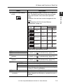
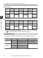
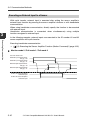
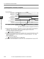
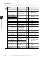
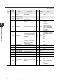
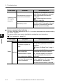
Power-On Reset Time
The NU-CL1 starts updating data a certain time (depending on the type and number
of sensor amplifiers connected, and the data to be read) after the power is turned on.
The start time can be changed using the fourth bit of the operation mode setting
switch.
Here are examples of start times for each mode of the FS-N10 digital fiber unit.
Data communication start time
2
Operation
mode
Data
communicated
Standard start
mode (factory
default setting)
Output and
current value
(cyclic communication)
Change setting value,
read/write
parameter, and
execute motion
command
When no
sensor
amplifier is
connected
When one or more sensor
amplifiers are connected
40 ms
120 ms + 30 ms x (number of
connected sensor amplifiers)
2 s x (number of connected sensor amplifiers)
- CC-Link Compatible Network Unit NU-CL1 User's Manual -
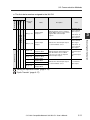
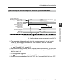
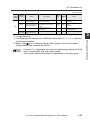
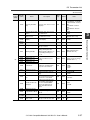
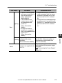
Safety Precautions
Data communication start time
Operation
mode
Data
communicated
Command-priority start
mode:
Output and
current value
(cyclic communication)
Change setting value,
read/write
parameter, and
execute motion
command
When no
sensor
amplifier is
connected
When one or more sensor
amplifiers are connected
35 ms
240 ms + 110 ms x (number of
connected sensor amplifiers)
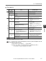
Notes on Regulations and Standards
UL Certificate
The NU-CL1 is an UL/C-UL Listed product:
• UL File No. E207185
• Categories: NRAQ, NRAQ7
Be sure to follow the specification below.
• Use a power supply that provides Class 2 output defined in NFPA70 (NEC:
National Electric Code).
• Use copper wire having a gage of AWG#12 to #24 and temperature rating of 60°C
or higher when wiring to the CC-Link connector and power supply connector.
• Pollution degree 2
CE Marking
The NU-CL1 complies with the essential requirements of EMC Directive. The following harmonized standards are applied.
EMI: EN55011, Class A
EMS: EN61000-6-2
• Be sure to install the NU-CL1 in a conductive enclosure such as a control panel.
• The length of the cable for wiring to the power supply connector must be 30 meters
or less.
- CC-Link Compatible Network Unit NU-CL1 User's Manual -
3
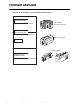
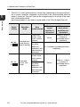
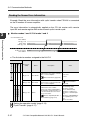
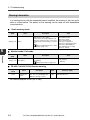
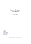
Relevant Manuals
The manuals to relevant to this document are as follows:
Manuals relevant to
CPU unit
Example: KV-5500 user's manual
PLC CPU unit
CC-Link master unit
Manuals relevant to
CC-Link master unit
Example: KV-CL20 user's manual
NU-CL1 (This unit)
This manual
Sensor amplifier
Manuals of sensor
amplifier main unit
Example: FS-N10 series user's manual
4
- CC-Link Compatible Network Unit NU-CL1 User's Manual -
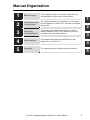
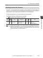
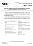
Manual Organization
Before Using
This chapter provides an overview of the NU-CL1
and describes its part names and functions.
Connection and
Configuration
This chapter explains the procedures for connecting
sensor amplifiers to the NU-CL1 and how to configure
the data link
3
Executing
Communication
This chapter describes the configuration of the
memory linked to the CC-Link master station and
provides communication methods.
4
Specifications
This chapter describes the specifications and
dimensions of the NU-CL1.
5
Appendix
1
2
1
2
3
4
This chapter provides troubleshooting instructions.
- CC-Link Compatible Network Unit NU-CL1 User's Manual -
5
5
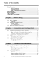
Table of Contents
Safety Precautions ........................................................................................... 1
General Precautions .......................................................................... 1
Precautions for Use............................................................................ 1
Notes on Regulations and Standards ................................................ 3
Relevant Manuals ............................................................................................. 4
Manual Organization ........................................................................................ 5
Table of Contents.............................................................................................. 6
Terms Used in This Document ......................................................................... 8
Chapter 1 Before Using
1-1
1-2
1-3
NU-CL1 Overview ................................................................................ 1-2
Overview ......................................................................................... 1-2
Checking the Package Contents.......................................................... 1-3
Package Content............................................................................. 1-3
List of Optional Parts....................................................................... 1-3
Names and Functions of Each Part ..................................................... 1-4
Chapter 2 Connection and Configuration
2-1
2-2
2-3
Installation and Connection to Sensor Amplifiers ................................ 2-2
Types and Number of Connectable Sensor Amplifiers.................... 2-2
ID Number Assignments to Sensor Amplifiers ................................ 2-3
Installing and Connecting Sensor Amplifiers................................... 2-4
Wiring................................................................................................... 2-6
Connecting to the CC-Link System ................................................. 2-6
Connecting the Power Supply ......................................................... 2-9
Configuring for Communication ......................................................... 2-11
Configuring the Master Station ..................................................... 2-11
Configuring the NU-CL1................................................................ 2-12
Chapter 3 Executing Communication
3-1
3-2
6
Operation with CC-Link and Memory Configuration ............................ 3-2
Overview ......................................................................................... 3-2
Station Organization and Memory Occupied .................................. 3-3
Assigning Data to ID Numbers........................................................ 3-3
Meaning of Each Item ..................................................................... 3-4
Communication Methods ..................................................................... 3-5
Overview ......................................................................................... 3-5
Reading the Sensor ON/OFF Output .............................................. 3-6
Reading the Sensor Current Value ................................................. 3-7
- CC-Link Compatible Network Unit NU-CL1 User's Manual -
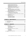
Table of Contents
3-3
3-4
3-5
Changing the Sensor Setting Value ................................................ 3-8
Executing an External Input to a Sensor....................................... 3-10
Reading the Sensor Error Information .......................................... 3-12
Disabling the Sensor Key Operations ........................................... 3-13
Displaying Random Characters on the Sensor ............................. 3-14
Reducing the Sensor Power Consumption ................................... 3-16
Cyclic Transfer.................................................................................... 3-17
Remote Input RX (NU-CL1 J Master Station).............................. 3-17
Remote Output RX (Master Station J NU-CL1) ........................... 3-19
Remote Register RWr (NU-CL1 J Master Station) ...................... 3-20
Remote Register RWr (Master Station J NU-CL1) ...................... 3-22
Handshake Communication............................................................... 3-23
(1) Reading the Sensor Amplifier Data ......................................... 3-23
(2) Writing Data to the Sensor Amplifier ....................................... 3-24
(3) Executing the Sensor Amplifier Function (Motion Command) ... 3-25
Command Response List.............................................................. 3-26
Parameter List.................................................................................... 3-27
NU-CL1 Parameters...................................................................... 3-27
FS-N10 Series Parameters ........................................................... 3-30
LV-N10 Series Parameters ............................................................ 3-40
PS-N10 Series Parameters ........................................................... 3-50
Chapter 4 Specifications
4-1
4-2
4-3
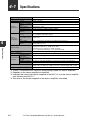
Specifications....................................................................................... 4-2
Data Processing Times........................................................................ 4-3
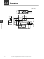
Dimensions .......................................................................................... 4-4
Chapter 5 Appendix
5-1
5-2
5-3
5-4
Troubleshooting.................................................................................... 5-2
LED Indicator Specifications ........................................................... 5-2
Error Information ............................................................................. 5-6
Warning Information........................................................................ 5-8
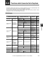
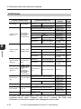
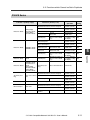
Functions which Cannot be Set in Duplicate ....................................... 5-9
FS-N10 Series ................................................................................ 5-9
LV-N10 Series ............................................................................... 5-10
PS-N10 Series .............................................................................. 5-11
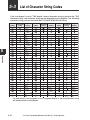
List of Character String Codes........................................................... 5-12
Index .................................................................................................. 5-14
- CC-Link Compatible Network Unit NU-CL1 User's Manual -
7
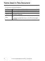
Terms Used in This Document
This document uses the following terms:
Term
Description
Sensor
Main unit
A sensor amplifier.
A sensor amplifier that has a power line and can operate alone.
A sensor amplifier that does not have a power line and must be
Expansion unit
connected to a main unit.
The name of KEYENCE's wiring-saving system for sensor amplifiers.
N-bus
For example, the digital fiber sensors of the FS-N series support
this system.
8
- CC-Link Compatible Network Unit NU-CL1 User's Manual -
Before Using
This chapter provides an overview of the NU-CL1 and describes its
part names and functions.
1-1
1-2
1-3
1
NU-CL1 Overview .............................................. 1-2
Checking the Package Contents ........................ 1-3
Names and Functions of Each Part.................... 1-4
- CC-Link Compatible Network Unit NU-CL1 User's Manual -
1-1
1-1
1
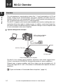
NU-CL1 Overview
Overview
Before Using
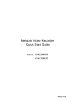
This unit operates as a remote device station (Ver. 1.1 and 2 switchable) of a CC-Link
system. Using CC-Link communications, the sensor amplifiers and other units connected to the NU-CL1 can transmit their ON/OFF control signals and measured values as communication data to a PLC or other equipment.
The NU-CL1 supports cyclic transfer and extended cyclic transfer, enabling data communication without the need of a ladder program. In addition, remote input/output signals can be used as handshake signals to read/write settings of sensor amplifiers and
to issue commands to the sensor amplifiers.
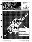
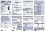
System configuration example
PLC or other host device
(CC-Link master unit)
NU-CL1 (This unit)
CC-Link slave
N-bus compatible sensor amplifier
The NU-CL1 can connect sensor amplifiers (expansion units) which support N-bus.
("N-bus" is the name of KEYENCE's wiring-saving system for sensor amplifiers.)
Different types of sensor amplifiers with N-bus support can be connected up to 16
units to the single NU-CL1 unit. (The number of connectable units depends on sensor
amplifiers.)
"Types and Number of Connectable Sensor Amplifiers" (page 2-2)
1-2
- CC-Link Compatible Network Unit NU-CL1 User's Manual -
1-2
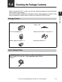
Checking the Package Contents
Before using the NU-CL1, make sure that the following equipment and accessories
are included in the package.
We have thoroughly inspected the package contents before shipment. However, in the
event of defective or broken items, contact your nearest KEYENCE office.
Before Using
Package Content
NU-CL1 main unit x 1
Termination resistor x 1
110 1/2W
(brown/brown/brown/gold)
CC-Link connector x 1
End unit (OP-26751; 2-unit set) x 1
Power supply connector x 1
Instruction manual x 1
List of Optional Parts
OP-79426 (CC-Link Ver. 1.10 compatible cable, 20 m)
OP-79427 (CC-Link Ver. 1.10 compatible cable, 100 m)
Cable x 1
- CC-Link Compatible Network Unit NU-CL1 User's Manual -
1
1-3
1-3
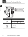
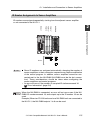
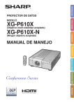
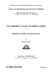
Names and Functions of Each Part
This section describes the part names and functions of the NU-CL1.
1
(1) Transmission rate setting switch
(2) Station number setting switch
Before Using
(3) Operation mode setting switch
(4) Power indicator (green)
(5) Communication indicator (green)
(6) Communication error indicator (red)
(7) Sensor communication indicator
(red/green)
(8) CC-Link connector
(9) Power supply connector
(10) Sensor amplifier connector
Name
(1) Transmission rate setting
switch
Description
Sets the transmission rate of CC-Link.
No.
Transmission
rate (bps)
(2) Station number setting
switch
0
156k
1
625k
2
2.5M
3
5M
5 to 9
10M
Cannot be
set.
Default value: 0
Sets the station number of the NU-CL1 in the CCLink.
x10 : Ten's digit
x1
: One's digit
Setting range: 01 to 64
Default value: 01
1-4
4
- CC-Link Compatible Network Unit NU-CL1 User's Manual -
1-3 Names and Functions of Each Part
Name
(3) Operation mode setting
switch
Description
switch.*
"Operation with CC-Link and Memory
Configuration" (page 3-2)
Switch
setting
Operation mode
Small-memory
mode
Monitor mode 1
Station
configuration
Number of link points
RX/RY
RWw/RWr
32 each
4 each
64 each
8 each
96 each
12 each
128 each
16 each
160 each
24 each
Ver.1.1
1-station, 1x
Ver.1.1
2-station, 1x
Monitor mode 2
Ver.1.1
3-station, 1x
Full mode 1
Ver.1.1
4-station, 1x
Full mode 2
Ver.2
3-station, 2x
Others
(4) Power indicator
(5) Communication indicator
(6) Communication error
indicator
(7) Sensor communication
indicator
(8) CC-Link connector
DA/DB/DG
SLD
FG
(9) Power supply connector
(10)Sensor amplifier
connector
Cannot be set.
-
-
Default value: Small-memory mode
When normal: Lit in green
For details, see
"Troubleshooting" (page 5-2).
When normal: Not lit
For details, see
"Troubleshooting" (page 5-2).
When normal: Lit in green
For details, see
"Troubleshooting" (page 5-2).
Attach the CC-Link cable to this connector.
Communication signal
Shielded wire of the CC-Link cable.
Ground this functional ground terminal according to
a Class D (Class 3) grounding.
Attach the power cable to this connector.
Attach the sensor amplifier to this connector.
When shipped from the factory, a protection cover is
installed.
- CC-Link Compatible Network Unit NU-CL1 User's Manual -
1-5
1
Before Using
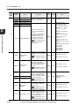
Sets the operation mode of the NU-CL1 in the CCLink. The specific data that can be communicated
using cyclic transfer varies with each operation
mode.
In addition, the start time can be changed with this
1-3 Names and Functions of Each Part
1
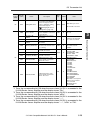
* The NU-CL1 starts updating data a certain time (depending on the type and number of sensor amplifiers connected, and the data to be communicated) after the
power is turned on. The start time can be changed using the fourth bit of the operation mode setting switch.
Here are examples of start times for each mode of the FS-N10 digital fiber unit.
Before Using
Data communication start time
Switch
setting
Operation
mode
Standard start
mode (factory
default setting)
Commandpriority start
mode:
1-6
Data
communicated
Output and
current value
(cyclic communication)
Change setting value,
read/write
parameter, and
execute motion
command
Output and
current value
(cyclic communication)
Change setting value,
read/write
parameter, and
execute motion
command
When no
sensor
amplifier is
connected
When one or
more sensor
amplifiers are
connected
40 ms
120 ms + 30 ms x
(number of
connected sensor
amplifiers)
2 s x (number of connected sensor
amplifiers)
35 ms
240 ms + 110 ms
x (number of
connected sensor
amplifiers)
- CC-Link Compatible Network Unit NU-CL1 User's Manual -
Connection and Configuration
This chapter explains the procedures for connecting sensor
amplifiers to the NU-CL1 and how to configure the data link.
2-1
2-2
2-3
2
Installation and Connection to Sensor Amplifiers ... 2-2
Wiring ................................................................. 2-6
Configuring for Communication ........................ 2-11
- CC-Link Compatible Network Unit NU-CL1 User's Manual -
2-1
2-1
Installation and Connection to Sensor Amplifiers
This section provides the procedures for installing the NU-CL1 on the DIN rail and
connecting to sensor amplifiers.
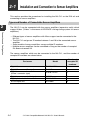
Types and Number of Connectable Sensor Amplifiers
2
Connection and Configuration
The NU-CL1 can be connected with the sensor amplifiers (expansion units) which
support N-bus. ("N-bus" is the name of KEYENCE's wiring-saving system for sensor
amplifiers.)
• Different types of sensor amplifiers with N-bus support can be connected to the
NU-CL1.
• The NU-CL1 assigns an ID number between 1 and 16 to the connected sensor
amplifier.
• Some models of sensor amplifiers occupy multiple ID numbers.
• Multiple sensor amplifiers can be connected as long as the number of occupied
IDs does not exceed 16.
The sensor amplifiers which can be connected to the NU-CL1, and the number of
occupied ID numbers are shown below.
Part name
Digital fiber sensor
Digital fiber sensor (2-output)
Digital laser sensor
(0-line / connector type)
Digital laser sensor (cable type)
Digital photoelectric sensor
e-CON input unit
2-2
Model
Number of
occupied ID
numbers
FS-N10 / N12*
FS-N14*
1
2
LV-N10 / N12C*
1
LV-N12*
PS-N10/N12*
NU-EN8N
2
1
8
- CC-Link Compatible Network Unit NU-CL1 User's Manual -
2-1 Installation and Connection to Sensor Amplifiers
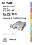
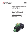
ID Number Assignments to Sensor Amplifiers
ID numbers are assigned sequentially, starting from the adjacent sensor amplifier
or unit connected to the NU-CL1.
FS-N12*
FS-N14*
NU-EN8N
2
3
4
5
6
Connection and Configuration
FS-N10
NU-CL1
ID No.
1
2
12
Point
• Since ID numbers are assigned automatically, changing the number of
sensor amplifiers or their connection sequence may require modification
of the control program. In addition, sensor amplifiers cannot be connected next to the the NU-EN8N (NU-EN8N must be the last connection). These considerations should be taken when configuring the
sensor amplifiers and control programs.
• An error will occur if the number of occupied ID stations exceeds 16.
"Error Information" (page 5-6)
Reference
When the NU-EN8N is connected, an error will not occur even if the NUEN8N ID number exceeds 16, and outputs up to the ID number 16 can be
used.
Example) When ten FS-N10 units and one NU-EN8N unit are connected to
the NU-CL1, the NU-EN8N outputs 1 to 6 can be used.
- CC-Link Compatible Network Unit NU-CL1 User's Manual -
2-3
2-1 Installation and Connection to Sensor Amplifiers
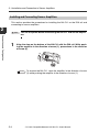
Installing and Connecting Sensor Amplifiers
This section provides the procedures for installing the NU-CL1 on the DIN rail and
connecting to sensor amplifiers.
2
Point
Connection and Configuration
1
Turn off the power before connecting the NU-CL1 and sensor amplifiers.
Align the claw on the bottom of the NU-CL1 with the DIN rail. While pushing the amplifier in the direction of arrow (1), press down in the direction
of arrow (2).
(3)
(2)
Reference
2-4
(1)
To remove the NU-CL1, raise the amplifier in the direction of arrow
(3) while pushing the amplifier in the direction of arrow (1).
- CC-Link Compatible Network Unit NU-CL1 User's Manual -
2-1 Installation and Connection to Sensor Amplifiers
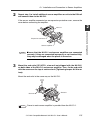
2
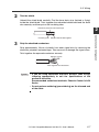
Repeat step 1 to install additional sensor amplifiers or units to the DIN rail
and connect them to the NU-CL1.
If the sensor amplifier connector has an expansion protective cover, remove the
cover before connecting the amplifier.
2
NU-CL1
Sensor amplifier
Point
3
Ensure that the NU-CL1 and sensor amplifiers are connected
securely. If they are connected improperly or not inserted fully,
they may be damaged when the power is turned on.
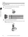
Mount the end units (OP-26751: a two-unit set shipped with the NU-CL1)
on both sides of the NU-CL1 and sensor amplifier. Then, fix the end units
with the screws on the top of each end unit (Tightening torque: 0.6 N•m or
less).
Mount the end units in the same way as the NU-CL1.
End unit
Reference
End unit
Power to each sensor amplifier is provided from the NU-CL1.
- CC-Link Compatible Network Unit NU-CL1 User's Manual -
2-5
Connection and Configuration
Expansion connector
2-2
Wiring
Use the following procedures to wire the NU-CL1.
Point
2
• Turn off the power before wiring.
• For more information on the CC-Link system, including the cable
length and wiring methods, refer to the CC-Link Installation Manual
issued by the CC-Link Organization or the CC-Link master unit's
manual.
Connection and Configuration
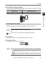
Connecting to the CC-Link System
Use the following procedures to connect the NU-CL1 to the CC-Link system.
Recommended cables
For connection between the NU-CL1 and the CC-Link system, use CC-Link cables
(Ver. 1.10 or later) accredited by the CC-Link Partner Association.
CC-Link cables (for Ver. 1.10) are available as optional items.
OP-79426 (20 m) OP-79427 (100 m)
Point
To ensure normal communication, only use the CC-Link cables.
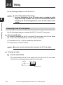
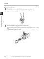
Trimming the cable
1
Strip the cable sheath.
Strip approximately 50 mm of the sheath from the end of the CC-Link cable,
with care to avoid damaging the shield braid of the cable.
Sheath
Approx. 50 mm
Shield braid
2-6
- CC-Link Compatible Network Unit NU-CL1 User's Manual -
2-2 Wiring
2
Trim the shield.
Unbraid the shield braid carefully. Find the bare drain wire (twisted or flying)
inside the shield braid. Twist together the unbraided shield braid and the drain
wire securely, and then put on the insulating tube.
Aluminum polyester laminated tape
2
3
Strip the sheathed conductors.
Strip approximately 10 mm of sheath from each signal wire, by removing the
aluminum polyester laminated tape. Take care not to damage the signal wires.
Twist together the exposed conductors securely.
Approx. 10 mm
Twist together the conductors.
Point
• If you are using solderless terminals, perform cable wiring/
trimming appropriately to suit the specifications of the
particular terminals.
Recommended solderless terminals: Phoenix Contact's A/AI
Series
• Do not perform soldering (pre-soldering) on the trimmed end
of the cable.
- CC-Link Compatible Network Unit NU-CL1 User's Manual -
2-7
Connection and Configuration
Insulating tube Shield braid twisted together
2-2 Wiring
Connecting the cable
Use the following procedures to connect to the CC-Link connector supplied with the
NU-CL1.
1
2
Connect the trimmed cable to the CC-Link connector.
Insert the cable completely.
Connection and Configuration
Terminal name
2
Function
DA/DB/DG
Communication signal
SLD
Connect the shielded wire of the CC-Link cable.
FG
Ground this functional ground terminal according to
Class D (Class 3) grounding..
Attach the CC-Link connector to the NU-CL1.
Plug the connector into the NU-CL1 and secure it down with the screws on each
end.
(Tightening torque: 0.2 to 0.3 N•m)
2-8
- CC-Link Compatible Network Unit NU-CL1 User's Manual -
2-2 Wiring
Connecting the termination resistor
If the NU-CL1 is at the end of the CC-Link system, connect the supplied termination
resistor to DA/DB of the CC-Link connector.
Type of cable
CC-Link Ver. 1.10 compatible cable
Termination resistor
110 , 1/2 W (brown/brown/brown/gold)
2
Connection and Configuration
Connecting the Power Supply
Use the following procedure to connect the power supply to the NU-CL1.
Point
Reference
The cable length should be 30 meters or less.
Power to each sensor amplifier is supplied from the NU-CL1.
Usable cable
Copper wire of AWG12 to 24 (rated temperature 60°C or higher).
Trimming the cable
Strip the end of the cable as shown below.
10 mm
Point
• If you are using solderless terminals, perform cable wiring/trimming appropriately to suit the specifications of the particular terminals. Recommended solderless terminals: Phoenix Contact's A/AI
Series
• Do not perform soldering (pre-soldering) on the trimmed end of the
cable.
- CC-Link Compatible Network Unit NU-CL1 User's Manual -
2-9
2-2 Wiring
Connecting the cable
1
Connect the trimmed cable to the power supply connector.
Insert the cable completely.
2
Connection and Configuration
2
Attach the power supply connector to the NU-CL1.
Plug the connector into the NU-CL1 and secure it down with the screws on each
end.
(Tightening torque: 0.2 to 0.3 N•m)
2-10
- CC-Link Compatible Network Unit NU-CL1 User's Manual -
2-3
Configuring for Communication
Use the following configuration procedures for connecting the NU-CL1 to the CC-Link
system.
Point
Configuring the Master Station
To connect the NU-CL1 to the CC-Link master unit, it is necessary to configure the
slave attribute and memory allocation settings.
Slave attribute settings
Register the NU-CL1 to the CC-Link master unit as a remote device station.
You can also configure the settings by importing a CSP file into the software for the
master unit (ladder programming software or CC-Link configuration software).
Reference
The CSP file can be downloaded from the KEYENCE web site:
http://www.keyence.co.jp
Memory allocation settings
In order to exchange data between the NU-CL1 and CC-Link master station,
configure the memory allocation settings using the software for the master station
(ladder programming software or CC-Link configuration software).
Reference
Where multiple slave units are connected, the memory allocation for each
slave unit is done automatically based on the specified starting address.
The allocation information for each slave unit can be checked using the
CC-Link configuration software.
- CC-Link Compatible Network Unit NU-CL1 User's Manual -
2-11
2
Connection and Configuration
This manual covers only the functions and settings of a CC-Link master station which are required for communication with the NU-CL1.
For the functions and settings related to the communication between
the CC-Link master unit and CPU unit, refer to the manuals shipped
with your master unit or CPU unit.
2-3 Configuring for Communication
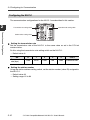
Configuring the NU-CL1
The communication configurations for the NU-CL1 are described in this section.
2
Transmission rate setting switch
Operation mode setting switch
Connection and Configuration
Station number setting switch
Setting the transmission rate
Set the transmission rate of the NU-CL1 to the same value as set in the CC-Link
master station.
Do this using the transmission rate setting switch on the NU-CL1.
• Default value: 0
No.
Transmission
rate (bps)
0
1
2
3
4
5 to 9
156k
625k
2.5M
5M
10M
Cannot be set.
Setting the station number
Using the station address setting switch, set the station number (slave ID) assigned to
the NU-CL1.
• Default value: 01
• Setting range: 01 to 64
2-12
- CC-Link Compatible Network Unit NU-CL1 User's Manual -
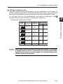
2-3 Configuring for Communication
Setting the operation mode
Using the operation mode setting switch, set the combination of the number of
stations occupied by the NU-CL1 and the extended cyclic setting. The specific data
that can be communicated using cyclic transfer varies with each operation mode.
For the data that can be communicated, and memory configuration, see
"Operation with CC-Link and Memory Configuration" (page 3-2).
• Default value: Small-memory mode
Operation mode
Small-memory
mode
Monitor mode 1
Station
configuration
Ver.1.1
Number of link points
RX/RY
RWw/RWr
32 each
4 each
64 each
8 each
96 each
12 each
128 each
16 each
160 each
24 each
Connection and Configuration
Switch
setting
1-station, 1x
Ver.1.1
2-station, 1x
Monitor mode 2
Ver.1.1
3-station, 1x
Full mode 1
Ver.1.1
4-station, 1x
Full mode 2
Ver.2
3-station, 2x
Others
Point
Cannot be set.
-
-
Each switch should be set before turning on the power. If any setting
is changed while the NU-CL1 is operating, the new setting will not be
applied until the power is turned on again. (The communication error
indicator flashes intermittently.)
- CC-Link Compatible Network Unit NU-CL1 User's Manual -
2
2-13
2-3 Configuring for Communication
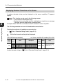
Changing the start time
The NU-CL1 starts updating data a certain time (depending on the type and number
of sensor amplifiers connected, and the data to be communicated) after the power is
turned on. The start time can be changed using the fourth bit of the operation mode
setting switch.
2
• Default value: Standard start mode
Switch setting
Start mode
Connection and Configuration
Standard start mode
Command-priority start mode
Here are examples of start times for each mode of the FS-N10 digital fiber unit.
Data communication start time
Operation
mode
Data
communicated
Standard start
mode (factory
default setting)
Command-priority start
mode:
2-14
Output and
current value
(cyclic communication)
Change setting value,
read/write
parameter, and
execute motion
command
Output and
current value
(cyclic communication)
Change setting value,
read/write
parameter, and
execute motion
command
When no
sensor
amplifier is
connected
When one or more sensor
amplifiers are connected
40 ms
120 ms + 30 ms x (number of
connected sensor amplifiers)
2 s x (number of connected sensor amplifiers)
35 ms
240 ms + 110 ms x (number of
connected sensor amplifiers)
- CC-Link Compatible Network Unit NU-CL1 User's Manual -
Executing Communication
This chapter describes the configuration of the memory linked to the
CC-Link master station and provides communication time charts.
3-1
3-2
3-3
3-4
3-5
3
Operation with CC-Link and Memory Configuration ....3-2
Communication Methods.................................... 3-5
Cyclic Transfer .................................................. 3-17
Handshake Communication ............................. 3-23
Parameter List .................................................. 3-27
- CC-Link Compatible Network Unit NU-CL1 User's Manual -
3-1
3-1
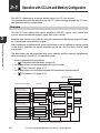
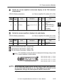
Operation with CC-Link and Memory Configuration
The NU-CL1 operates as a remote device station of a CC-Link system.
This section describes the data that the NU-CL1 can exchange through the CC-Link,
and specific memory configuration.
Overview
The NU-CL1 can retrieve the sensor amplifier's ON/OFF signals, error status and
current value and execute external inputs with cyclic transfer.
3
Executing Communication
Detailed data transfer is possible by using the remote input RX/remote output RY area
as a handshake communication signal.
With handshake communication, motion commands such as calibration can be issued
to the sensor amplifier, the sensor amplifier can be set, and the status can be read
and written.
The data which can be exchanged with cyclic transfer and the memory assignments
differ according to the NU-CL1's operation mode.
• Actual communication procedures
J
"Communication Methods" (page 3-5)
• List of data which can be exchanged with cyclic transfer
J
"Cyclic Transfer" (page 3-17)
• List of data which can be communicated with handshake communication
J
"Parameter List" (page 3-27)
Sensor amplifier
Output
CC-Link master station
NU-CL1
Current value
Output
RX (remote inputs)
RWr (remote registers)
Current value
Error information
Output
Output
Current value
Operation mode
Current value
Error information
Error information
Operation mode
Read parameter
RY (remote inputs)
RWw (remote registers)
Error information
Setting value
Calibration
Setting value
Operation mode
Request to change setting value
Calibration
Changed setting value
Setting value
External input
Calibration
Write parameter
Read/write parameters
3-2
- CC-Link Compatible Network Unit NU-CL1 User's Manual -
3-1 Operation with CC-Link and Memory Configuration
Station Organization and Memory Occupied
Switch
setting
Number of link points
Station
configuration
RX/RY
RWw/RWr
Operation mode
Ver.1.1
1-station, 1x
32 each
4 each
Monitor mode 1
Ver.1.1
2-station, 1x
64 each
8 each
Monitor mode 2
Ver.1.1
3-station, 1x
96 each
12 each
Full mode 1
Ver.1.1
4-station, 1x
128 each
16 each
Full mode 2
Ver.2
3-station, 2x
160 each
24 each
Others
Cannot be set.
Assigning Data to ID Numbers
The number of occupied ID numbers and the ID numbers used for communication
differ according to the connected sensor amplifier. Refer to the following table for
details.
Output
ID No.
FS-N10
FS-N12*
1st
Output
2nd
FS-N14*
LV-N10
LV-N12C*
Output 1
Output
Output 2
LV-N12*
PS-N10
PS-N12*
NU-EN8N
Output 1
Output
No.1 output
Output 2
No. 2 output
·
·
·
·
·
·
8th
No. 8 output
- CC-Link Compatible Network Unit NU-CL1 User's Manual -
3-3
3
Executing Communication
Small-memory mode
3-1 Operation with CC-Link and Memory Configuration
Current value
ID No.
FS-N10
FS-N12*
LV-N10
LV-N12C*
LV-N12*
PS-N10
PS-N12*
NU-EN8N
Current value Current value Current value Current value Current value
or received or received or received or received or received
light intensity light intensity light intensity light intensity light intensity
1st
2nd
3
FS-N14*
Not used
Not used
Not used
Not used
·
·
·
·
·
·
8th
Not used
Executing Communication
External input
ID No.
FS-N10
FS-N12*
FS-N14*
LV-N10
LV-N12C*
LV-N12*
PS-N10
PS-N12*
NU-EN8N
1st
External
input
External
input
External
input
External
input
External
input
Not used
2nd
Not used
Not used
Not used
·
·
·
·
·
·
8th
Not used
For details of the ID number assignments
J
"ID Number Assignments to Sensor Amplifiers" (page 2-3)
Meaning of Each Item
The meaning of each item used in the list on the following pages are as follows:
Item
Data type
Attribute
3-4
Value
INT
UINT
WORD
R
R/W
W
C
Meaning
16-bit signed integer
16-bit unsigned integer
16-bit data
Read enabled
Read/write enabled
Write enabled
Motion command
Range
-32768 to 32767
0 to 65535
-
- CC-Link Compatible Network Unit NU-CL1 User's Manual -
-
3-2
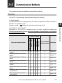
Communication Methods
This section describes the detailed communication methods.
Overview
The NU-CL1 can exchange data with the following two methods.
(1) Cyclic transfer
The data which can be exchanged and the memory assignments differ according to
the NU-CL1's operation mode.
Operation mode J
"Setting the operation mode" (page 2-13)
(1) Cyclic transfer
Full mode 2
Full mode 1
Monitor mode 2
Monitor mode 1
Reading the Sensor ON/OFF
Output
Reading the Sensor Current
Value*
Changing the Sensor Setting
Value
Executing an External Input to a
Sensor
Reading the Sensor Error Information
Disabling the Sensor Key Operations
Displaying Random Characters
on the Sensor
Reducing the Sensor Power
Consumption
Small-memory mode
Types of communication
(2) Handshake
Reference
communication
c c c c c
c
page 3-6
–
4
8
12 16
c
page 3-7
–
–
–
c c
c
page 3-8
c
–
c c c
c
page 3-10
c c c c c
c
page 3-12
–
c c c c
c
page 3-13
–
c c c c
c
page 3-14
–
c c c c
c
page 3-16
- CC-Link Compatible Network Unit NU-CL1 User's Manual -
3-5
Executing Communication
(2) Handshake communication
Regardless of the NU-CL1's operation mode, all sensor amplifier's settings and
statuses can be read and written. Note that handshake communication is not possible
in the Small-memory mode.
3
3-2 Communication Methods
* The listed numbers indicate the number of sensor amplifiers for which the current
value is read out (total number of occupied ID numbers).
"Installation and Connection to Sensor Amplifiers" (page 2-2)
The functions shown above are an example of what can be used with communication.
Refer to the following sections for information on other functions.
• Finding data which can be transferred with cyclic transfer
J
"Cyclic Transfer" (page 3-17)
• Checking all data which can be communicated
3
J
"Handshake Communication" (page 3-23)
Executing Communication
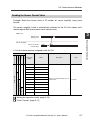
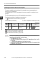
Reading the Sensor ON/OFF Output
Example: Read the ID number 01 sensor amplifier's ON/OFF output state using cyclic
transfer.
The sensor amplifier's data is automatically reflected on the CC-Link master unit's
remote input RX area at each cyclic transfer cycle.
Master unit
Output ID 01
RX [n] + 00
1
0
Sensor amplifier
ID No. 01 Sensor
Output
ON
OFF
n: The first device number assigned to the NU-CL1
Operation mode
Device No.
(HEX)
RX [n] + 00
Can be used in all
modes
Name
:
Indicates each ID number sensor's ON/OFF
output.
Output ID 16
"Cyclic Transfer" (page 3-17)
3-6
Value
Output ID 01
:
RX [n] + 0F
Description
- CC-Link Compatible Network Unit NU-CL1 User's Manual -
0: Output OFF
1: Output ON
3-2 Communication Methods
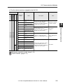
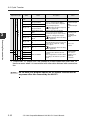
Reading the Sensor Current Value
Example: Read the current value of ID number 01 sensor amplifier using cyclic
transfer.
The sensor amplifier's data is automatically reflected on the CC-Link master unit's
remote register RWr area at each cyclic transfer cycle.
Master unit
500
ID No. 01 Sensor
Current value
500
3
520
Executing Communication
Output ID 01
RWr [n] + 04
Sensor amplifier
520
n: The first device number assigned to the NU-CL1
Operation mode
Full 2
Full 1
Monitor 2
Monitor 1
Small-memory
Device No.
(HEX)
RWr [n] + 04
Name
Value
Current Value ID 01
:
:
RWr [n] + 07
Current Value ID 04
RWr [n] + 08
Current Value ID 05
:
:
Current Value ID 08
RWr [n] + 0C
Current Value ID 09
:
Non-assigned
Non-assigned
Non-assigned
Non-assigned
RWr [n] + 0B
Expresses each ID number sensor's
current value.
0 to 9999
:
RWr [n] + 0F
Current Value ID 12
RWr [n] + 10
Current Value ID 13
:
RWr [n] + 13
Description
:
Current Value ID 16
"Setting the operation mode" (page 2-13)
"Cyclic Transfer" (page 3-17)
- CC-Link Compatible Network Unit NU-CL1 User's Manual -
3-7
3-2 Communication Methods
Changing the Sensor Setting Value
Example: Change the ID number 01 and 02 sensor amplifier setting values with cyclic
transfer.
The sensor amplifier setting value is changed by storing the setting value to be written
in a specific register and turning the setting value write request bit ON.
CC-Link master unit
3
Executing Communication
Setting value ID 01
RWw [n] + 04
100
Setting value ID 02
RWw [n] + 05
300
Setting write request ID 01
RY [n] + 50
Setting write request ID 02
RY [n] + 51
Setting write complete ID 01*
RX [n] + 50*
Setting write complete ID 02*
RX [n] + 51*
Sensor amplifier
Setting value of sensor amplifier
ID No. 01
Setting value of sensor amplifier
ID No. 02
100
300
*The “sensor setting value change error” (RX[n]+60 / RX[n]+61) bit turns ON when an error occurs.
3-8
- CC-Link Compatible Network Unit NU-CL1 User's Manual -
3-2 Communication Methods
n: The first device number assigned to the NU-CL1
Operation mode
Full 2
Full 1
Monitor 2
Monitor 1
Small-memory
Device No.
(HEX)
RX [n] + 50
Name
Setting Write Finish
ID 01
:
:
Setting Write Finish
ID 16
RX [n] + 60
Setting Write Error ID
01
:
:
Non-assigned
Non-assigned
Non-assigned
RX [n] + 6F
Setting Write Error ID
16
RY [n] + 50
Setting Write Request
ID 01
:
:
RY [n] + 5F
Setting Write Request
ID 16
RWw [n] + 04
Setting Value ID 01
:
Non-assigned
Indicates that each ID number sensor process end normally in
response to the remote output RY
“setting value write request”.
0: Write incomplete
1: Write complete
Indicates that an error occurred in
each ID number sensor in
response to the remote output RY
“setting value write request”.
0: No Error
1: Error
Indicates a setting value write
request to each ID number sensor.
0 J 1: Setting write
request
Indicates the setting value written
to each ID number sensor in
response to the remote output RX
“setting value write request”.
0 to 9999
:
RWw [n] + 0F
Setting Value ID 12
RWw [n] + 10
Setting Value ID 13
:
RWw [n] + 13
Value
:
Setting Value ID 16
"Setting the operation mode" (page 2-13)
"Cyclic Transfer" (page 3-17)
- CC-Link Compatible Network Unit NU-CL1 User's Manual -
3-9
3
Executing Communication
RX [n] + 5F
Description
3-2 Communication Methods
Executing an External Input to a Sensor
3
With cyclic transfer, external input is executed after setting the sensor amplifier's
external input function by pressing the sensor amplifier's buttons or with handshake
communication.
When using handshake communication, directly specify the function to be executed
with external input.
Handshake communication is convenient when simultaneously using multiple
functions assigned to external input.
Executing Communication
In the following example, external inputs are executed to the ID number 01 and 02
sensor amplifiers with cyclic transfer.
Executing handshake communication
J
"(3) Executing the Sensor Amplifier Function (Motion Command)" (page 3-25)
Monitor mode 2 / Full mode 1 / Full mode 2
CC-Link master unit
External input request ID 01
RY [n] + 40
External input request ID 02
RY [n] + 41
External input response ID 01
RX [n] + 40
External input response ID 02
RX [n] + 41
Sensor amplifier
ID No. 01 sensor amplifier
External input
ID No. 02 sensor amplifier
External input
3-10
- CC-Link Compatible Network Unit NU-CL1 User's Manual -
3-2 Communication Methods
n: The first device number assigned to the NU-CL1
Operation mode
Full 2
Full 1
Monitor 2
Monitor 1
Small-memory
Device No.
(HEX)
RWr [n] + 02
Name
External Input
Response
External Input
Request
RX [n] + 40
External Input
Response ID 01
:
:
Non-assigned
RX [n] + 4F
External Input
Response ID 16
RY [n] + 40
External Input
Request ID 01
:
RY [n] + 4F
:
Value
Indicates that the sensor's external
input is ON in response to the remote
register RWw “external input
request”.
Bit0: ID No. 01
sensor external
input response
:
Bit15: ID No. 16
sensor external
input response
Indicates the external input request
to each ID number sensor.
Bit0: ID No. 01
sensor external
input request
:
Bit15: ID No. 16
sensor external
input request
Indicates that the external input for
each ID number sensor is ON in
response to the remote output RY
“external input request”.
0: External input
OFF
1: External input
ON
Indicates the external input request
to each ID number sensor.
0J1: External
input request
External Input
Request ID 16
"Setting the operation mode" (page 2-13)
"Cyclic Transfer" (page 3-17)
- CC-Link Compatible Network Unit NU-CL1 User's Manual -
3-11
3
Executing Communication
Non-assigned
Non-assigned
Non-assigned
Non-assigned
RWw [n] + 02
Description
3-2 Communication Methods
Reading the Sensor Error Information
Example: Read the error information with cyclic transfer when FS-N10 is connected
as the ID number 01 sensor amplifier.
The error information is automatically applied on the CC-Link master unit's remote
input RX and remote register RWr areas at each cyclic transfer cycle.
3
Monitor modes 1 and 2 / Full mode 1 and 2
CC-Link master unit
Executing Communication
Error status
RX [n] + 18
Error code
RWr [n] + 00
Sensor amplifier
ID No. 01 sensor
error status
0101h (Overcurrent error)
0000h (No error)
No error
Overcurrent error
0000h (No error)
No error
n: The first device number assigned to the NU-CL1
Operation mode
Full 2
Full 1
Monitor 2
Monitor 1
Small-memory
Device No.
(HEX)
Name
Description
Value
Non-assigned
RX [n] + 18
Error Status
Indicates the error status of the NU0: No error
CL1 or sensor amplifier.
1: Error
"Error Information" (page 5-6)
RWr [n] + 00
Error Code
Indicates the error information
when an error occurred on the NUCL1 or sensor amplifier.
Non-assigned
Non-assigned
Non-assigned
Non-assigned
RWr [n] + 01
Status
Indicates the sensor status.
Refer to the remote input [RX18 to
1F] when the operation mode is set
to monitor/full mode for the meaning of each status.
"Remote Input RX (NU-CL1 J
Master Station)" (page 3-17)
"Error Information"
(page 5-6)
Bit0: Error status
Bit1: Warning status
Bit2: Sensor ready
Bit3: Command ready
Bit4: Sensor setting error
Bit5: Sensor external input
busy
Bit6: Sensor EEPROM busy
Bit7: Updating sensor setting
Bit8 to 15: 0 fixed
"Setting the operation mode" (page 2-13)
"Cyclic Transfer" (page 3-17)
3-12
- CC-Link Compatible Network Unit NU-CL1 User's Manual -
3-2 Communication Methods
Disabling the Sensor Key Operations
The keys of all connected sensor amplifiers can be locked via communication. In
addition to key lock which can be executed and canceled with the sensor amplifier's
key operations, key lock which can be disabled only via communication.
The following parameters are set with handshake communication.
Checking the methods of handshake communication
J
SubIndex
(HEX)
01
0000
Name
All Unit Key Lock
Description
Executes or cancels the
designated key lock set
for all amplifiers.
Data
type
Attribute
UINT
WO
Value
0: Unlock
1: Key Lock
2: PIN Code Lock
3: Communication Lock
Key lock and PIN code lock can be executed and canceled with the sensor
amplifier's key operations. For the operation procedure, refer to the User's
Manual of each sensor amplifier. Communication key lock can only be executed and canceled via communication.
- CC-Link Compatible Network Unit NU-CL1 User's Manual -
3-13
Executing Communication
Index
(HEX)
Reference
3
"Handshake Communication" (page 3-23)
3-2 Communication Methods
Displaying Random Characters on the Sensor
A random character string can be displayed on the sensor amplifier's 7-segment
display.
This function can be used in the following manner.
• Use instead of identification tags.
• Monitor the incoming light amount, and display an original error message
if the light amount drops below a specified level.
Example: When FS-N10 is connected as the ID number 01 sensor amplifier.
Reference
3
The following parameters are set with handshake communication.
Executing Communication
Checking the methods of handshake communication
J
1
"List of Character String Codes" (page 5-12)
Write the character string to be displayed.
(FS-N10 Series parameters)
Data
Data No.
category
(HEX)
(HEX)
00
Name
Description
nnE2
TAG Strings 1, 2
Indicates 1st and 2nd characters.
nnE3
TAG Strings 3, 4
Indicates 3rd and 4th characters.
nnE4
TAG Strings 5, 6
Indicates 5th and 6th characters.
nnE5
TAG Strings 7, 8
Indicates 7th and 8th characters.
Usable character strings J
3-14
nn: Sensor amplifier ID number (01 to 10h)
Data
type
Attribute
Value
WORD
R/W
(2-byte character string)
(Default value: "")
"List of Character String Codes" (page 5-12)
- CC-Link Compatible Network Unit NU-CL1 User's Manual -
3-2 Communication Methods
2
Switch the sensor amplifier's sub-screen display to the TAG character
string display.
(FS-N10 Series parameters)
nn: Sensor amplifier ID number (01 to 10h)
z: Default value
Data
Data No.
category
(HEX)
(HEX)
00
Sub Display
Description
Indicates details of the sub
display.
Data
type
INT
Attribute
R/W
Value
0: Nonez
1: Extension
2: Bar
3: Excess Gain (%)
4: Light Intensity HOLD
5: Excess Gain HOLD
(%)
6: L-on/D-on
7: TAG Strings
Switch the sensor amplifier's display to the sub-display.
(FS-N10 Series parameters)
nn: Sensor amplifier ID number (01 to 10h)
z: Default value
Data
Data No.
category
(HEX)
(HEX)
00
nnC6
Name
Current Display
Description
Indicates current display.
Data
type
Attribute
INT
R/W
Value
0: Normalz
1: Sub
"FS-N10 Series Parameters" (page 3-30)
"LV-N10 Series Parameters" (page 3-40)
"PS-N10 Series Parameters" (page 3-50)
Reference
The method for storing the data to display the following string on the
sensor amplifier is shown below.
TAG character string 1, 2: 4241h
TAG character string 3, 4: 4443h
TAG character string 5, 6: 4645h
41 42 43 44 45 46 47 48 h
Point
TAG character string 7, 8: 4847h
When displaying a tag character string using 2-output type amplifiers,
set the slide style DIP switch to 1ch. The display will not switch to the
tag character string if the slide style DIP switch is set to 2ch.
- CC-Link Compatible Network Unit NU-CL1 User's Manual -
3-15
3
Executing Communication
3
nnC2
Name
3-2 Communication Methods
Reducing the Sensor Power Consumption
The sensor amplifier can be switched to the standby state via communication to
reduce the consumed power.
The method when FS-N10 is connected as the sensor amplifier is explained as an
example.
The following parameters are set with handshake communication.
3
Checking the methods of handshake communication
J
"Handshake Communication" (page 3-23)
Executing Communication
(FS-N10 Series parameters)
nn: Sensor amplifier ID number (01 to 10h)
z: Default value
Data
Data No.
category
(HEX)
(HEX)
00
nn32
Name
Description
Data
type
Attribute
Operation Mode Setting
Set up the operation mode
of the sensor.
INT
R/W
Value
0: RUNz
1: LED_OFF
2: SLEEP
3: PAUSE
"FS-N10 Series Parameters" (page 3-30)
"LV-N10 Series Parameters" (page 3-40)
"PS-N10 Series Parameters" (page 3-50)
Point
3-16
The sensor amplifier operates in the following method while the
"operation mode setting" is set to sleep.
• The light emission stops.
• The ON/OFF output remains fixed at OFF regardless of the L-on/Don setting.
• "-" sequentially appears on the display screen.
• If keys are activated, the display screen returns to the normal state
for approx. four seconds.
- CC-Link Compatible Network Unit NU-CL1 User's Manual -
3-3
Cyclic Transfer
This section explains the data which can be exchanged with cyclic transfer.
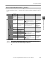
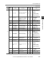
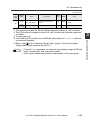
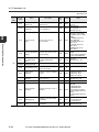
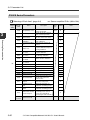
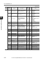
Remote Input RX (NU-CL1 J Master Station)
In the descriptions below, "n" denotes the first device number assigned to the NU-CL1.
Operation mode
Device No.
(HEX)
Small-memory
RX [n] + 00
:
Name
Output ID 01
:
Output ID 16
RX [n] + 10
Command Finish
RX [n] + 11
Indicates each ID number sensor's
ON/OFF output.
"Reading the Sensor ON/OFF
Output" (page 3-6)
Indicates that the process for the remote
output RY "command request" is finished.
Value
0: Output OFF
1: Output ON
"Handshake Communication"
(page 3-23)
0: Process not
finished
1: Process
finished
Current Value
Update Locked
Indicates that the current value
update is locked in response to the
remote output RY "current value
update lock request".
0: Updating
current value
1: Current value
update locked
RX [n] + 12
to 17
System reserved
-
-
RX [n] + 18
Error Status
Indicates the error status of the NUCL1 or sensor amplifier.
"Error Information" (page 5-6)
RX [n] + 19
Warning Status
Indicates the warning status of the
sensor amplifier.
"Warning Information" (page 5-
0: No error
1: Error
0: No warning
1: Warning
Full mode 2
Full mode 1
Monitor mode 2
Monitor mode 1
8)
RX [n] + 1A
RX [n] + 1B
Sensor Ready
Indicates the sensor ready status.
Command Ready
Indicates that a command can be
requested to execute handshake
communication.
"Handshake Communication"
(page 3-23)
Indicates the sensor setting error status.
0: Sensor
amplifier ready
1: Sensor
amplifier in
normal operation
0: Command
request disabled
1: Command
request enabled
0: Normal
1: Error
RX [n] + 1C
Sensor Setting Error
RX [n] + 1D
Sensor External Input
Busy
Indicates the status of the external
input process using sensor wiring.
*External inputs set via
communication are not possible
during external inputs set via wiring.
0: External input
off
1: External input
busy
RX [n] + 1E
Sensor EEPROM
Busy
Indicates the status of the EEPROM
process after changing the sensor
settings.
0: Not writing to
EEPROM
1: Writing to
EEPROM
RX [n] + 1F
Updating Sensor
Setting
Indicates the status of the setting
application process after changing
the sensor settings.
0: Settings
updated
1: Updating
settings
RX [n] + 20
to 2F
System reserved
-
-
"Functions which Cannot be
Set in Duplicate" (page 5-9)
- CC-Link Compatible Network Unit NU-CL1 User's Manual -
3-17
3
Executing Communication
RX [n] + 0F
Description
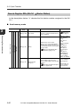
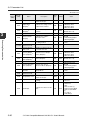
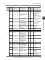
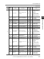
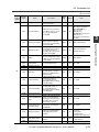
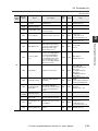
3-3 Cyclic Transfer
Operation mode
Monitor mode 2
Name
Description
RX[n] + 30
to 3F
System reserved
-
RX [n] + 40
External Input
Response ID 01
Indicates that each ID number
sensor's external input is ON in
response to the remote output RY
"external input request".
:
Full mode 2
Full mode 1
3
Device No.
(HEX)
:
RX [n] + 4F
External Input
Response ID 16
RX [n] + 50
Setting Write Finish
ID 01
:
:
"Executing an External Input to
a Sensor" (page 3-10)
Indicates that each ID number
sensor's process has finished
normally in response to the remote
output RY "setting write request".
Executing Communication
RX [n] + 5F
Setting Write Finish
ID 16
"Changing the Sensor Setting
Value" (page 3-8)
RX [n] + 60
Setting Write Error ID
01
Indicates that an error occurred in
each ID number sensor in response
to the remote output RY "setting
write request".
:
RX [n] + 6F
:
Setting Write Error ID
16
"Changing the Sensor Setting
Value" (page 3-8)
Remote READY
Indicates the status of
communication with the CC-Link
system.
*The assigned device number differs
according to the NU-CL1 operation
mode.
RX [n] + 1B
RX [n] + 3B
RX [n] + 5B
RX [n] + 7B
RX [n] + 9B
Value
-
0: External input
OFF
1: External input
ON
0: Setting write
incomplete
1: Setting write
finish
0: No error
1: Error
0: Error (Data
from sensor
amplifier is not
updated.)
1: Normal
*1 "Output ID01" to "output ID16" are updated at a faster speed than other data, so
there are cases when it is inconsistent with other data retrieved with communication.
Point
3-18
Do not have your program operate on the system reserved area or
any areas other than reserved by the NU-CL1.
- CC-Link Compatible Network Unit NU-CL1 User's Manual -
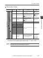
3-3 Cyclic Transfer
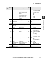
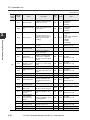
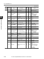
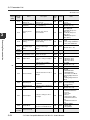
Remote Output RX (Master Station J NU-CL1)
In the descriptions below, "n" denotes the first device number assigned to the NUCL1.
Operation mode
Device No.
(HEX)
Name
Small-memory
RY [n] + 10
Command Request
RY [n] + 11
Current Value Update
Lock Request
RY [n] + 12
to 2F
System reserved
RY [n] + 30
to 3F
System reserved
RY [n] + 40
External Input
Request ID 01
-
Full mode 2
Full mode 1
:
RY [n] + 4F
External Input
Request ID 16
RY [n] + 50
Setting Write Request
ID 01
:
RY [n] + 5F
Point
:
:
Setting Write Request
ID 16
"Handshake Communication"
(page 3-23)
Value
3
-
0 J 1: Command
request
Indicates the sensor current value
update stop request state.
0: No current
value update lock
request
1: Current value
update lock
requested
-
-
Indicates the external input request
to each ID number sensor.
"Executing an External Input to
a Sensor" (page 3-10)
Indicates the setting write request to
each ID number sensor.
"Changing the Sensor Setting
Value" (page 3-8)
0 J 1: External
input request
0 J 1: Setting
write request
Do not have your program operate on the system reserved area or
any areas other than reserved by the NU-CL1.
- CC-Link Compatible Network Unit NU-CL1 User's Manual -
3-19
Executing Communication
System reserved
Used as a trigger to read/write data
with handshake communication.
Monitor mode 2
Monitor mode 1
RY [n] + 00
to 0F
Description
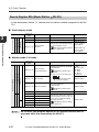
3-3 Cyclic Transfer
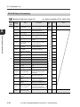
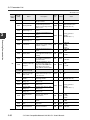
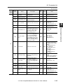
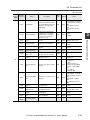
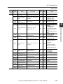
Remote Register RWr (NU-CL1 J Master Station)
In the descriptions below, "n" denotes the first device number assigned to the NUCL1.
Small-memory mode
3
Operation mode
Device No.
(Hex)
RWr [n] + 00
Full mode 2
Full mode 1
Monitor mode 2
Monitor mode 1
Small-memory mode
Executing Communication
RWr [n] + 01
Name
Error Code
Status
Description
Indicates the error information when
an error occurred on the NU-CL1 or
sensor amplifier.
Indicates the sensor status.
*Refer to the remote input [RX18 to
1F] when the operation mode is set
to monitor/full mode for the meaning
of each status.
"Remote Input RX (NU-CL1 J
Master Station)" (page 3-17)
RWr [n] + 02
External Input
Response
Indicates that the sensor's external
input is ON in response to the
remote register RWw "external input
request".
"Executing an External Input to
a Sensor" (page 3-10)
3-20
- CC-Link Compatible Network Unit NU-CL1 User's Manual -
Value
"Error Information" (page 56)
Bit0: Error status
Bit1: Warning
status
Bit2: Sensor
ready
Bit3: Command
ready
Bit4: Sensor
setting error
Bit5: Sensor
external input
busy
Bit6: Sensor
EEPROM busy
Bit7: Updating
sensor setting
Bit8 to 15: 0 fixed
Bit0: ID No. 01
sensor external
input response
:
Bit15: ID No. 16
sensor external
input response
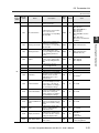
3-3 Cyclic Transfer
Monitor mode / Full mode
Operation mode
Device No.
(Hex)
RWr [n] + 00
RWr [n] + 01
Name
Error Code
Command Response
Description
Indicates the error information when
an error occurred on the NU-CL1 or
sensor amplifier.
Indicates the command process
results in response to the remote
output RY "command request".
Indicates the read data when
reading data with handshake
communication.
Read Data
"Error Information" (page 56)
"Command
Response List"
(page 3-26)
0000 to FFFFh
"Handshake Communication"
(page 3-23)
Full mode 2
Small-memory mode
RWr [n] + 03
System reserved
RWr [n] + 04
Current Value ID 01
:
Current Value ID 04
RWr [n] + 08
Current Value ID 05
Current Value ID 08
RWr [n] + 0C
Current Value ID 09
Current Value ID 12
RWr [n] + 10
Current Value ID 13
RWr [n] + 13
RWr [n] + 14
0 to 9999
:
RWr [n] + 0F
:
Expresses each ID number sensor's
current value.
:
RWr [n] + 0B
:
-
:
RWr [n] + 07
:
-
:
Current Value ID 16
Current Value
Property
Turns the corresponding bit ON if the
current value of the connected
sensor exceeds the upper/lower
limits or if it is invalid.*1
Bit0: ID No. 01
sensor current
value property
:
Bit15: ID No. 16
sensor current
value property
*1 Turns the corresponding bit ON when the sensor head LV-S31 is connected to the
LV-N10 Series sensor amplifier and the display shows "----", "nEAr" or "FAr".
Point
Do not have your program operate on the system reserved area or
any areas other than reserved by the NU-CL1.
- CC-Link Compatible Network Unit NU-CL1 User's Manual -
3-21
3
Executing Communication
RWr [n] + 02
Full mode 1
Monitor mode 2
Monitor mode 1
"Handshake Communication"
(page 3-23)
Value
3-3 Cyclic Transfer
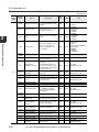
Remote Register RWr (Master Station J NU-CL1)
In the descriptions below, "n" denotes the first device number assigned to the NUCL1.
Small-memory mode
Operation mode
Full mode 2
Full mode 1
Monitor mode 2
Monitor mode 1
Executing Communication
Small-memory mode
3
Device No.
(Hex)
Name
Description
RWw [n] + 00
System reserved
-
RWw [n] + 01
System reserved
-
RWw [n] + 02
External Input
Request
Value
-
Indicates the external input request
to each ID number sensor.
"Executing an External Input to
a Sensor" (page 3-10)
Bit0: ID No. 01
sensor external
input request
:
Bit15: ID No. 16
sensor external
input request
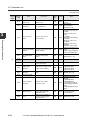
Monitor mode / Full mode
Operation mode
Device No.
(Hex)
RWw [n] + 00
Full mode 2
Full mode 1
Monitor mode 2
Small-memory mode
Monitor mode 1
Value
Upper 1 byte: 00
to FFh
Lower 1 byte:
00: Read
01: Write
02: Motion
command
"Handshake Communication"
(page 3-23)
h
RWw [n] + 01
RWw [n] + 02
Data number
Data to be written
Command number
Data category
Indicates the write data when writing
data with handshake
communication.
0000 to FFFFh
0000 to FFFFh
"Handshake Communication"
(page 3-23)
RWw [n] + 03
System reserved
RWw [n] + 04
Setting value ID 01
:
RWw [n] + 0F
Setting value ID 12
RWw [n] + 10
Setting value ID 13
:
RWw [n] + 13
3-22
Data category/
Command number
Description
Specifies the read/write data when
reading/writing data with handshake
communication.
*Methods of storing data in RWw[n]+00
:
Point
Name
:
Setting value ID 16
Indicates the setting value written to
each ID number sensor in response
to the remote output RX "setting
value write request".
0000 to 9999
"Changing the Sensor Setting
Value" (page 3-8)
Do not have your program operate on the system reserved area or
any areas other than reserved by the NU-CL1.
- CC-Link Compatible Network Unit NU-CL1 User's Manual -
3-4
Handshake Communication
The NU-CL1 realizes handshake communication by using the remote input RX and
remote output RY areas as handshake communication signals. This enables more
detailed data to be exchanged. With handshake communication, the sensor amplifier
settings and status can be read and written, and functions, such as calibration, can be
executed to the amplifier (motion commands can be executed).
• List of data which can be communicated with handshake communication
J
"Parameter List" (page 3-27)
• List of devices usable for communication timing control
J
3
"Remote Input RX (NU-CL1 J Master Station)" (page 3-17)
Executing Communication
(1) Reading the Sensor Amplifier Data
CC-Link master unit
Data category/Command number
RWw [n] + 00
xx00h
Data number
RWw [n] + 01
xxxxh
Command number (Read command = 00h)
Data category
Command request
RY [n] + 10
Command finish
RX [n] + 10
Command response
RWr [n] + 01
xxxxh
Read data
RWr [n] + 02
xxxxh
Sensor amplifier
Sensor amplifier data
[n]: The first device number assigned to the NU-CL1
(1) The parameter of the data to be read is stored in "Data category/command No."
and "data No.", and the "command request" bit turns ON.
• List of data categories and data numbers
J
"Parameter List" (page 3-27)
(2) After communicating with the sensor amplifier, the "command finish" bit turns ON,
and communication results are stored in "command response". The read data is
stored in "read data".
• List of command responses
J
"Command Response List" (page 3-26)
(3) When the "command request" bit turns OFF, the "command finish" bit turns OFF.
- CC-Link Compatible Network Unit NU-CL1 User's Manual -
3-23
3-4 Handshake Communication
(2) Writing Data to the Sensor Amplifier
CC-Link master unit
Data category/Command number
RWw [n] + 00
xx01h
Data number
RWw [n] + 01
xxxxh
Write data
RWw [n] + 02
xxxxh
3
Command number (Write command = 01h)
Data category
Command request
RY [n] + 10
Executing Communication
Command finish
RX [n] + 10
Command response
RWr [n] + 01
xxxxh
Read data
RWr [n] + 02
0000h
Sensor amplifier
Sensor amplifier data
[n]: The first device number assigned to the NU-CL1
(1) The parameter of the data to be written is stored in "data category/command No.",
"data No.", and "write data", and the "command request" bit turns ON.
• List of data categories and data numbers
J
"Parameter List" (page 3-27)
(2) After communicating with the sensor amplifier, the "command finish" bit turns ON,
and the communication results are stored in "command response". The "read
data" is reset to 0.
• List of command responses
J
"Command Response List" (page 3-26)
(3) When the "command request" bit turns OFF, the "command finish" bit turns OFF.
3-24
- CC-Link Compatible Network Unit NU-CL1 User's Manual -
3-4 Handshake Communication
(3) Executing the Sensor Amplifier Function (Motion Command)
CC-Link master unit
Data category/Command number
RWw [n] + 00
xx02h
Data number
RWw [n] + 01
xxxxh
Command number (Motion command = 02h)
Data category
3
Command request
RY [n] + 10
Command response
RWr [n] + 01
xxxxh
Read data
RWr [n] + 02
0000h
Sensor amplifier
Sensor amplifier data
[n]: The first device number assigned to the NU-CL1
(1) The parameter of the function of which the motion command is to be issued is
stored in "data category/command No." and "data No.", and the "command
request" bit turns ON.
• List of data category and data numbers
J
"Parameter List" (page 3-27)
(2) After communicating with the sensor amplifier, the "command finish" bit turns ON,
and the communication results are stored in "command response". The "read
data" is reset to 0.
• List of command responses
J
"Command Response List" (page 3-26)
(3) When the "command request" bit turns OFF, the "command finish" bit turns OFF.
- CC-Link Compatible Network Unit NU-CL1 User's Manual -
3-25
Executing Communication
Command finish
RX [n] + 10
3-4 Handshake Communication
Command Response List
Response
(Hex)
0000
3
0001
Executing Communication
0003
0004
0002
0005
0006
0007
0008
0009
000A
000B
3-26
Name
Description
The command has been processed
successfully.
Command number error
The command number is out of range.
The data category value is out of
Data category error
range.
ID number out of range
A nonexisting ID number is specified.
Data number out of range
The data number is out of range.
An attempt was made to write in a
Write inhibit
read-only data number.
Write data out of range
The value of write data is out of range.
An error occurred in the communicaSensor-to-sensor communi- tion between sensors.
cation error
Example: Noise, improper contact,
etc.
Motion command area
An attempt was made to read/write to
access error
a motion command area.
Motion command address
The address is out of range. (The
error
address is not used with this sensor.)
Motion command execution
Failed to execute a motion command.
error
An attempt was made to read data of a
Read inhibit
write-only data number.
Successfully completed
- CC-Link Compatible Network Unit NU-CL1 User's Manual -
3-5
Parameter List
The parameters used with handshake communication are listed below.
NU-CL1 Parameters
"Meaning of Each Item" (page 3-4)
Data
Data No.
category
(HEX)
(HEX)
Name
nn: Sensor amplifier ID No. (00 to 10h)
Description
Data
type
Attribute
3
Value
nn00
:
Depends on the sensor amplifiers connected.
nnFF
01
0000
All Unit Key Lock
Executes or cancels the
designated key lock set for
all amplifiers.
UINT
W
0: Cancel
1: Key lock
2: PIN key lock
3: Communication key
lock
02
0000
Output
When the ON/OFF output of
each ID number sensor is
ON, the corresponding bit
turns ON.
WORD
R
Bit0: ID No. 01 sensor
:
Bit15: ID No. 16 sensor
0001
Current Value Over
Range*1
When the current value of
each ID number sensor
exceeds the upper limit, the
corresponding bit turns ON.
WORD
R
Bit0: ID No. 01 sensor
:
Bit15: ID No. 16 sensor
0002
Current Value Under
Range*2
When the current value of
each ID number sensor
exceeds the lower limit, the
corresponding bit turns ON.
WORD
R
Bit0: ID No. 01 sensor
:
Bit15: ID No. 16 sensor
0003
Current Value
Invalid*3
When the current value of
each ID number sensor is
invalid, the corresponding
bit turns ON.
WORD
R
Bit0: ID No. 01 sensor
:
Bit15: ID No. 16 sensor
0004
Current Value
Property*4
When the current value of
each ID number sensor
exceeds the upper/lower
limit or is invalid, the
corresponding bit turns ON.
WORD
R
Bit0: ID No. 01 sensor
:
Bit15: ID No. 16 sensor
0040
Error Information
Indicates the error
information when an error
occurred on the NU-CL1 or
sensor amplifier.
WORD
R
"Error Information"
(page 5-6)
R
Bit0: Error status
Bit1: Warning status
Bit2: Sensor ready
Bit3: 0 fixed
Bit4: Sensor setting error
Bit5: Sensor external
input busy
Bit6: Sensor EEPROM
busy
Bit7: Updating sensor
setting
Bit8 to 15: 0 fixed
03
0041
Status
Indicates the status of all
connected sensors as OR.
*Refer to the remote input
[RX18 to 1F] when the
operation mode is set to
monitor/full mode for the
meaning of each status.
"Remote Input RX (NUCL1 J Master Station)"
(page 3-17)
WORD
- CC-Link Compatible Network Unit NU-CL1 User's Manual -
3-27
Executing Communication
00
3-5 Parameter List
Data
Data No.
category
(HEX)
(HEX)
0101
:
Name
:
Current Value ID 16
0201
Status/Output ID 01
03
Executing Communication
Attribute
Expresses each ID number
sensor's current value.
INT
R
0 to 9999
WORD
R
Bit15: Error status
Bit14: Warning status
Bit13: Sensor ready
Bit12: Motion command
error
Bit11: Sensor setting
error
Bit10: Sensor external
input busy
Bit9: Sensor EEPROM
busy
Bit8: Updating sensor
setting
Bit7: Current value over
range
Bit6: Current value under
range
Bit5: Current value invalid
Bit4: 0 fixed
Bit3: 0 fixed
Bit2: Output 3
Bit1: Output 2
Bit0: Output 1
WORD
R/W
Bit0: ID No. 01 sensor
:
Bit15: ID No. 16 sensor
WORD
R
Bit0: ID No. 01 sensor
:
Bit15: ID No. 16 sensor
INT
R/W
-32768 to 32767
*Depends on sensor
amplifiers.
WORD
R/W
Bit0: ID No. 01 sensor
:
Bit15: ID No. 16 sensor
R/W
Bit0: ID No. 01 sensor
:
Bit15: ID No. 16 sensor
:
3
0210
Data
type
Status/Output ID 16
Indicates the status and
output of each ID number
sensor.
*Refer to the remote input
[RX18 to 1F] when the
operation mode is set to
monitor/full mode for the
meaning of each status.
"Remote Input RX (NUCL1 J Master Station)"
(page 3-17)
0000
0001
External Input
Request
External Input
Response
Indicates the external input
request to each ID number
sensor.
"Executing an External
Input to a Sensor" (page 310)
Indicates that the sensor's
external input is ON in
response to the remote register RWw "external input
request".
"Executing an External
Input to a Sensor" (page 310)
0101
Setting Value ID 01
04
:
:
0110
Setting Value ID 16
0120
Setting Write
Request
0121
Value
Current Value ID 01
0110
:
Description
Setting Write Finish
Indicates the setting value
written to each ID number
sensor in response to the
remote output RX "setting
value write request".
"Changing the Sensor
Setting Value" (page 3-8)
Indicates a setting value
write request to each ID
number sensor.
"Changing the Sensor
Setting Value" (page 3-8)
Indicates that each ID number sensor process end normally in response to the
remote output RY "setting
WORD
value write request".
"Changing the Sensor
Setting Value" (page 3-8)
3-28
- CC-Link Compatible Network Unit NU-CL1 User's Manual -
3-5 Parameter List
Data
Data No.
category
(HEX)
(HEX)
04
0122
Name
Setting Write Error
Description
Indicates that an error
occurred in each ID number
sensor in response to the
remote output RY "setting
value write request".
Data
type
Attribute
WORD
R/W
UINT
R
Value
Bit0: ID No. 01 sensor
:
Bit15: ID No. 16 sensor
"Changing the Sensor
Setting Value" (page 3-8)
0000
Sensor Count
Indicates the number of
sensor amplifiers connected
to the NU-CL1.
0101
1st Sensor ID
Number
Indicates the 1st sensor's
ID number.
:
:
:
Indicates the 16th sensor's
ID number.
0200
Warning ID Number
Indicates the ID number of
the sensor at which an error
is occurring.
0401
Product Code ID01
Indicates the product code
of ID No. 01 sensor.
:
:
:
0410
Product Code ID16
Indicates the product code
of ID No. 16 sensor.
0501
Head Code ID01
Indicates the type of the
sensor head connected to
ID No. 01 sensor.
05
:
:
3
UINT
R
0: Sensor unconnected
1 to 16: Sensor ID No.
UINT
R
0: No warning
1 to 16: Sensor ID
number
R
FS-N10/N12*: 2000
FS-N14*: 2001
LV-N10/N12C*: 2003
LV-N12*: 2004
PS-N10/N12*: 2005
R
FS-N10 Series
Not available
LV-N10 Series
1: LV-S71
2: LV-S61
3: LV-S72
4: LV-S62
5: LV-S41/S41L
6: LV-S31
8: LV-S63
9: LV-NH37/NH42
10: LV-NH32/NH35
11: LV-NH100/NH110
12: LV-NH300
13: LV-NH62
The value is non-specific
when a sensor head is
not connected.
PS-N10 Series
Not available
WORD
:
INT
0510
Head Code ID16
Indicates the type of the
sensor head connected to
ID No. 16 sensor.
*1 Turns the corresponding bit ON when the sensor head LV-S31 is connected to the
LV-N10 Series sensor amplifier and the display shows "FAr".
*2 Turns the corresponding bit ON when the sensor head LV-S31 is connected to the
LV-N10 Series sensor amplifier and the display shows "nEAr".
*3 Turns the corresponding bit ON when the sensor head LV-S31 is connected to the
LV-N10 Series sensor amplifier and the display shows "----".
*4 Turns the corresponding bit ON when the sensor head LV-S31 is connected to the
LV-N10 Series sensor amplifier and the display shows "----", "nEAr" or "FAr".
- CC-Link Compatible Network Unit NU-CL1 User's Manual -
3-29
Executing Communication
0110
16th Sensor ID
Number
0 to 16
3-5 Parameter List
FS-N10 Series Parameters
"Meaning of Each Item" (page 3-4)
Data
Data No.
category
(HEX)
(HEX)
3
Executing Communication
00
Description
Data
type
Attribute
UINT
R
nn00
Group0 Entry count
Indicates the number of
entries in Group 0.
nn01
Load Recipe Data
Reads the mode selected
with "Recipe Select".
C
nn02
Custom Save
Writes the current settings
into the custom save area.
C
nn03
Maximum Sensitivity
Setting
Executes maximum sensitivity calibration.
C
nn04
Percentage Calibration
Executes percentage calibration.
C
nn05
Two-point/Pos. Calibration (1st)
Designates the 1st point for
2-point calibration and positioning calibration.
C
nn06
Two-point Calibration (2nd)
Designates the 2nd point for
2-point calibration.
C
nn07
Positioning Calibration (2nd)
Designates the 2nd point for
positioning calibration.
C
nn08
Full Auto Calibration
start
Starts full-auto calibration.
C
nn09
Full Auto Calibration
end
Ends full-auto calibration.
C
nn0A
Zero-shift start
Executes zero shift.
C
nn0B
Zero-shift end
Cancels zero shift.
C
nn0C
Preset start
Executes preset.
C
nn0D
Preset end
Cancels preset.
C
nn0E
Saturation Canceling start
Executes the saturation circuit.
C
nn0F
Saturation Canceling end
Cancels the saturation circuit.
C
nn10
Reset Hold Value
Resets the hold value such
as the peak value and bottom value.
C
nn11
Work-Preset
Request*1
Executes work preset.
C
nn12
Full Auto Preset:
Start*1
Starts fully automatic (or
maximum sensitivity) preset.
C
nn13
Full Auto Preset:
Finish*1
Ends fully automatic (or
maximum sensitivity) preset.
C
nn14
Maximum Sensitivity
Preset: Request*1
Executes maximum
sensitivity preset. (Preset
can be executed without
specifying the start and end.)
C
nn15 to
nn1F
3-30
Name
nn: Sensor amplifier ID No. (00 to 10h)
Value
16
System reserved
- CC-Link Compatible Network Unit NU-CL1 User's Manual -
3-5 Parameter List
z: Default value
Data
Data No.
category
(HEX)
(HEX)
nn20
Group1 Entry count
Description
Indicates the number of
entries in Group 1.
Data
type
Attribute
UINT
R
19
R
Bit0: Over Current Error
Bit1: Reserve
Bit2: EEPROM Error
Bit3: Reserve
Bit4: Reserve
Bit5: DATUM Correction
Error
Bit6: APC Error
Bit7: Sensor Communication Error
Value
Indicates the error information. If an error has
occurred, the corresponding
bit turns ON.
Warning Information
Indicates the warning information. If a warning has
occurred, the corresponding
bit turns ON.
WORD
R
Bit0: Limit Detection
nn23
Warning Function
Indicates the warning function working status. The
corresponding bit turns ON
if the warning function is
active.
WORD
R
Bit0: Limit Detection
(Default value: 0)
nn24
Output
Indicates the sensor output
status. If the output is ON,
the corresponding bit turns
ON.
WORD
R
Bit0: Output1
Bit1: Output2
nn25
Current Value
Indicates the current
received light amount.
INT
R
0 to 9999
nn26
System reserved
-
-
-
-
nn27
System reserved
-
-
-
-
nn28
Raw Value
Indicates the received light
amount before it is adjusted
with the preset function,
DATUM function or zero
shift function.
INT
R
0 to 65535 *2
nn29
Peak-Hold Value
Indicates the peak value of
the received light (or maximum value of the bottom
value). (Differs according to
the hold display setting.)
INT
R
0 to 9999
nn2A
Bottom-Hold Value
Indicates the bottom value
of the received light (or minimum value of the peak
value). (Varies according to
the hold display setting)
INT
R
0 to 9999
nn2B
System reserved
-
-
-
-
nn2C
Peak-Hold Minimum
Value
Indicates the smallest maximum received light amount
while it exceeds the setting
value.
INT
R
0 to 9999
nn2D
DATUM Internal
Value
Indicates the setting value
prior to scaling with the
DATUM function.
INT
R
0 to 65535 *2
nn2E
Display Customize
Indicates the operation status of the function compensating the display value.
INT
R
0: No Customize /
DATUM z
1: Preset
2: Zero-shift
nn2F
Slide Switch Status
Indicates the status of the
slide switch.
INT
R
0: Selecting SEL
1: Selecting MEGA
nn22
WORD
- CC-Link Compatible Network Unit NU-CL1 User's Manual -
3-31
3
Executing Communication
Error Information
nn21
00
Name
3-5 Parameter List
z: Default value
Data
Data No.
category
(HEX)
(HEX)
3
Executing Communication
Name
Description
Data
type
Attribute
nn30
Saturation Canceling
Indicates the execution status of the saturation circuit
function.
INT
R
0: Not Active
1: Active
nn31
Operation Mode
Indicates the sensor’ s current operation mode.
INT
R
0: RUNz
1: LED_OFF
2: SLEEP
3: PAUSE
nn32
Operation Mode Setting
Sets the sensor’ s operation
mode.
INT
R/W
0: RUNz
1: LED_OFF
2: SLEEP
3: PAUSE
Recipe Select
Selects the application setting to be read with the
motion command "Load
Recipe Data".
INT
R/W
0: Initializez
1: Custom
2: Fall
3: Percentage Calibration
4: Zero-shift
5: MEGA
6: AREA*1
7: 0 DATUM*1
-
-
-
UINT
R
7
nn33
nn34 to
nn3F
00
System reserved
-
nn40
Group2 Entry count
Indicates the number of
entries in Group 2.
nn41
Setting Value
(Output1 / Area Hi)
Indicates the output 1 setting value.
If the "Detection mode" is
set to area detection mode,
the upper limit of the setting
value is indicated.
INT
R/W
0 to 9999
(Default value: 50)
nn42
Setting Value
(Output2)*3
Indicates the output 2 setting value.
INT
R/W
0 to 9999
(Default value: 50)
-
-
INT
R/W
nn43
System reserved
-
nn44
Setting Value (Area
Low)
Indicates the lower limit of
the setting value in the area
detection mode.
nn45
System reserved
-
-
-
-
nn46
System reserved
-
-
-
-
Limit Setting Value
Indicates the setting value
for outputting a warning
while using the limit detection function.
INT
R/W
nn47
3-32
Value
0 to 9999
(Default value: 50)
0 to 9999
(Default value: 0)
nn48
to nn4F
System reserved
-
-
-
-
nn50
[Custom] Group2
Entry count
Number of entries in the
Group 2 custom save area
UINT
R
7
nn51
[Custom] Setting
Value (Output1 /
Area Hi)
Custom save area for "Setting Value (Output1)"
INT
R/W
0 to 9999
(Default value: 50)
nn52
[Custom] Setting
Value (Output2)*3
Custom save area for "Setting Value (Output2)*1"
INT
R/W
0 to 9999
(Default value: 50)
-
-
INT
R/W
nn53
System reserved
-
nn54
[Custom] Setting
Value (Area Low)
Custom save area for "Setting Value (Area Low)"
-
nn55
System reserved
-
-
-
-
nn56
System reserved
-
-
-
-
nn57
[Custom] Limit Setting Value
Custom save area for "Limit
Setting Value"
INT
R/W
0 to 9999
(Default value: 50)
0 to 9999
(Default value: 0)
- CC-Link Compatible Network Unit NU-CL1 User's Manual -
3-5 Parameter List
z: Default value
Data
Data No.
category
(HEX)
(HEX)
nn58
to nn5F
Name
Description
Data
type
Attribute
-
-
-
UINT
R
7
Value
System reserved
-
nn60
Group3 Entry count
Indicates the number of
entries in Group 3.
nn61
Key Lock Status
Indicates the key lock status.
INT
R/W
0: Unlockz
1: Key Lock
2: PIN Code Lock
3: Communication Lock
nn62
PIN Code
Indicates the PIN for using
the PIN key lock.
INT
R/W
0 to 9999
(Default value: 0)
Slide Switch Lock
Indicates the lock status of
the slide switch. If locked,
the slide switch is disabled,
and is fixed at SEL (1 for
FS-N14). *4
INT
R/W
0: Unlockz
1: Lock
L-on/D-on (N.O./
N.C.)
Indicates whether the output is received light ON (Lon) or interrupted ON (Don). Indicates the output
logic (NO/NC) when using
the area detection mode.
The corresponding bit turns
ON in D-on or NC.
WORD
R/W
Bit0: Output1
Bit1: Output2*3
(Default value: 0)
nn63
nn65
Power Mode
Indicates the power mode.
INT
R/W
0: HIGH SPEED
(Response Time 50 Ps)
1: FINE (Response Time
250 Ps)z
2: TURBO
(Response Time 500us)
3: SUPER
(Response Time 1ms)
4: ULTRA
(Response Time 4ms)
5: MEGA
(Response Time 16ms)
nn66
Sensitivity Setting
Indicates the sensitivity setting method.
INT
R/W
0: Normal Sensitivity Settingz
1: Percentage Calibration
2: Zero-shift Calibration
nn67
Percentage Calib.
Target Value
Indicates the percent calibration target value when
the "Sensitivity Setting" is
set to Percent Calibration.
INT
R/W
-99 to 99
(Default value: -10)
00
nn68
to nn6F
System reserved
-
-
-
-
nn70
[Custom] Group3
Entry count
Number of entries in the
Group 3 custom save area
UINT
R
7
nn71
[Custom] Key Lock
Status
Custom save area for "Key
Lock Status"
INT
R/W
0: Unlockz
1: Key Lock
2: PIN Code Lock
3: Communication Lock
nn72
[Custom] PIN Code
Custom save area for "PIN
Code"
INT
R/W
0 to 9999
(Default value: 0)
- CC-Link Compatible Network Unit NU-CL1 User's Manual -
3-33
Executing Communication
nn64
3
3-5 Parameter List
z: Default value
Data
Data No.
category
(HEX)
(HEX)
3
Executing Communication
00
3-34
Name
Description
Data
type
Attribute
Value
nn73
[Custom] Slide
Switch Lock
Custom save area for "Slide
Switch Lock"
INT
R/W
0: Unlockz
1: Lock
nn74
[Custom] L-on/D-on
(N.O./N.C.)
Custom save area for "L-on/
D-on (N.O./N.C.)"
WORD
R/W
Bit0: Output1
Bit1: Output2*3
(Default value: 0)
nn75
[Custom] Power
Mode
Custom save area for
"Power Mode"
INT
R/W
0: HIGH SPEED
(Response Time 50 Ps)
1: FINE
(Response Time 250
Ps)z
2: TURBO
(Response Time 500 Ps)
3: SUPER
(Response Time 1ms)
4: ULTRA
(Response Time 4ms)
5: MEGA
(Response Time 16ms)
nn76
[Custom] Sensitivity
Setting
Custom save area for "Sensitivity Setting"
INT
R/W
0: Normal Sensitivity Settingz
1: Percentage Calibration
2: Zero-shift Calibration
nn77
[Custom] Percentage Calib. Target
Value
Custom save area for "Percentage Calib. Target
Value"
INT
R/W
-99 to 99
(Default value: -10)
nn78
to nn7F
System reserved
-
-
-
-
nn80
Group4 Entry count
Indicates the number of
entries in Group 4.
UINT
R
9
nn81
Output Timer
(Output1)
Indicates the settings for the
output 1 timer function.
INT
R/W
0: Timer Offz
1: Off-delay Timer
2: On-delay Timer
3: One-shot Timer
nn82
Timer Value
(Output1)
Indicates the output 1 timer
time.
INT
R/W
1 to 9999
(Default value: 10)
nn83
System reserved
-
-
-
-
nn84
Detection Mode
(Output1)
Indicates the output 1
detection mode.
INT
R/W
0: Normal Detection
Modez
1: DATUM1 Mode
2: DATUM2 Mode
3: Area Detection Mode
4: Rising Edge Detection
Mode
5: Falling Edge Detection
Mode
nn85
DATUM Speed
Indicates the compensation
speed when using the
DATUM function.
INT
R/W
0: Level1 (Slow)z
1: Level2 (Normal)
2: Level3 (Fast)
nn86
DATUM Warning
Level
Indicates the warning output level when using the
DATUM function.
INT
R/W
0 to 100
(Default value: 50)
- CC-Link Compatible Network Unit NU-CL1 User's Manual -
3-5 Parameter List
z: Default value
Data
Data No.
category
(HEX)
(HEX)
Name
Description
Data
type
Attribute
Value
nn87
Control Input
Indicates the settings for the
external input function.
INT
R/W
0: Not usez
1: External Calibration
2: Preset
3: Zero-shift
4: Reset
5: Transmission OFF
6: PAUSE Mode Transition
7: SLEEP Mode Transition
nn88
PAUSE Mode
Set the output state for
when the sensor's "Operation Mode" is set to pause
mode.
INT
R/W
0: Always OFFz
1: Always ON
2: Keep Output
nn89
Light Emission Power
Switches the emission
power.
INT
R/W
1 to 100
(Default value: 100)
nn8A
to 8F
System reserved
-
-
-
-
nn90
[Custom] Group4
Entry count
Number of entries in the
Group 4 custom save area
UINT
R
9
nn91
[Custom] Output
Timer (Output1)
Custom save area for
"Timer function (Output 1)"
INT
R/W
0: Timer Offz
1: Off-delay Timer
2: On-delay Timer
3: One-shot Timer
nn92
[Custom] Timer
Value (Output1)
Custom save area for
"Timer time (Output 1)"
INT
R/W
1 to 9999
(Default value: 10)
nn93
System reserved
-
-
-
3
Executing Communication
-
nn94
[Custom] Detection
Mode (Output1)
Custom save area for
"Detection mode (Output 1)"
INT
R/W
0: Normal Detection
Modez
1: DATUM1 Mode
2: DATUM2 Mode
3: Area Detection Mode
4: Rising Edge Detection
Mode
5: Falling Edge Detection
Mode
nn95
[Custom] DATUM
Speed
Custom save area for
"DATUM Speed"
INT
R/W
0: Level1 (Slow)z
1: Level2 (Normal)
2: Level3 (Fast)
nn96
[Custom] DATUM
Warning Level
Custom save area for
"DATUM Warning Level"
INT
R/W
0 to 100
(Default value: 50)
00
nn97
[Custom] Control
Input
Custom save area for "Control Input"
INT
R/W
0: Not usez
1: External Calibration
2: Preset
3: Zero-shift
4: Reset
5: Transmission OFF
6: PAUSE Mode Transition
7: SLEEP Mode Transition
nn98
[Custom] PAUSE
Mode
Custom save area for
"PAUSE Mode"
INT
R/W
0: Always OFFz
1: Always ON
2: Keep Output
nn99
[Custom] Light Emission Power
Custom save area for "Light
Emission Power"
INT
R/W
1 to 100
(Default value: 100)
System reserved
-
-
-
nn9A
to nn9F
-
- CC-Link Compatible Network Unit NU-CL1 User's Manual -
3-35
3-5 Parameter List
z: Default value
Data
Data No.
category
(HEX)
(HEX)
3
Description
Data
type
Attribute
UINT
R
Value
nnA0
Group5 Entry count
Indicates the number of
entries in Group 5.
nnA1
Output Timer
(Output2)*3
Indicates the settings for the
output 2 timer function.
INT
R/W
0: Timer Offz
1: Off-delay Timer
2: On-delay Timer
3: One-shot Timer
nnA2
Timer Value
(Output2)*3
Indicates the output 2 timer
function.
INT
R/W
1 to 9999
(Default value: 10)
nnA3
System reserved
-
-
-
5
-
Executing Communication
nnA4
Detection Mode
(Output2)
Indicates the output 2
detection mode.
INT
R/W
0: Normal Detection
Modez
1: Limit Setting Output
2: Warning Output
nnA5
Limit Output Mode
Indicates the limit output
resetting method.
INT
R/W
0: Manualz
1: Auto
-
-
-
UINT
R
5
nnA6
to nnAF
System reserved
-
nnB0
[Custom] Group5
Entry count
Number of entries in Group
5 custom save area
nnB1
[Custom] Output
Timer (Output2)*3
Custom area for "Output
Timer (Output2)"
INT
R/W
0: Timer Offz
1: Off-delay Timer
2: On-delay Timer
3: One-shot Timer
nnB2
[Custom] Timer
Value (Output2)*3
Custom area for "Timer
Value (Output2)"
INT
R/W
1 to 9999
(Default value: 10)
nnB3
System reserved
-
-
-
00
-
nnB4
[Custom] Detection
Mode (Output2)
Custom save area for
"Detection Mode (Output2)"
INT
R/W
0: Normal Detection
Modez
1: Limit Setting Output
2: Warning Output
nnB5
[Custom] Limit Output Mode
Custom save area for "Limit
Output Mode"
INT
R/W
0: Manualz
1: Auto
nnB6
to BF
System reserved
-
-
-
-
nnC0
Group6 Entry count
Indicates the number of
entries in Group 6.
UINT
R
6
nnC1
Display Reverse
Displays the display reverse
settings.
INT
R/W
0: Normalz
1: Reverse
R/W
0: Nonez
1: Extension
2: Bar
3: Excess Gain (%)
4: Light Intensity HOLD
5: Excess Gain HOLD
(%)
6: L-on/D-on
7: TAG Strings
nnC2
3-36
Name
Sub Display
Indicates the subscreen display.
INT
- CC-Link Compatible Network Unit NU-CL1 User's Manual -
3-5 Parameter List
z: Default value
Data
Data No.
category
(HEX)
(HEX)
Name
Description
Data
type
Attribute
Value
Hold Display
Indicates the contents being
held when Light Intensity
HOLD is selected for "Sub
Display".
INT
R/W
0: Normalz
1: Peak Max. / Peak Min.
2: Bottom Max. / Bottom
Min.
3: Peak Min. / Bottom
Max.
4: Peak Max. / Bottom
Min.
nnC4
Preset Saturation
Indicates whether to saturate the current received
light amount value when
using the preset or DATUM
functions.
INT
R/W
0: Off
1: Onz
nnC5
Preset Saturation
Level
Indicates the saturation
level for preset.
INT
R/W
100 to 200
(Default value: 110)
nnC6
Current Display
Indicates the current display
screen.
INT
R/W
0: Normalz
1: Sub
System reserved
-
-
-
-
nnD0
[Custom] Group6
Entry count
Indicates the number of
entries in the Group 6 custom save area.
UINT
R
6
nnD1
[Custom] Display
Reverse
Custom save area for the
"Display Reverse"
INT
R/W
0: Normalz
1: Reverse
R/W
0: Nonez
1: Extension
2: Bar
3: Excess Gain (%)
4: Light Intensity HOLD
5: Excess Gain HOLD
(%)
6: L-on/D-on
7: TAG Strings
nnC3
00
nnD2
[Custom] Sub Display
Custom save area for "Sub
Display"
INT
nnD3
[Custom] Hold Display
Custom save area for "Hold
Display"
INT
R/W
0: Normalz
1: Peak Max. / Peak Min.
2: Bottom Max. / Bottom
Min.
3: Peak Min. / Bottom
Max.
4: Peak Max. / Bottom
Min.
nnD4
[Custom] Preset Saturation
Custom save area for "Preset Saturation"
INT
R/W
0: Off
1: Onz
nnD5
[Custom] Preset Saturation Level
Custom save area for "Preset Saturation Level"
INT
R/W
100 to 200
(Default value: 110)
nnD6
[Custom] Current
Display
Custom save area for "Current Display"
INT
R/W
0: Normalz
1: Sub
nnD7
to nnDF
System reserved
-
-
-
-
- CC-Link Compatible Network Unit NU-CL1 User's Manual -
3-37
Executing Communication
nnC7
to nnCF
3
3-5 Parameter List
z: Default value
Data
Data No.
category
(HEX)
(HEX)
Name
Description
Data
type
Attribute
Value
nnE0
Group7 Entry count
Indicates the number of
Group 7 entries.
UINT
R
nnE1
Warning Disable
Indicates the warning function
prohibit settings. If the bit is
ON, the corresponding warning
will not occur.
WORD
R/W
Bit0: Limit Detection
(Default value: 0)
nnE2
TAG Strings 1,0
Indicates 1st and 2nd characters.
3
nnE3
TAG Strings 3,2
Indicates 3rd and 4th characters.
R/W
nnE4
TAG Strings 5,4
Indicates 5th and 6th characters.
WORD
(2-byte character
string)*5
(Default value: "")
Executing Communication
nnE5
TAG Strings 7,6
Indicates 7th and 8th characters.
nnE6
Power Save
Indicates the energy saving
function’ s status.
INT
R/W
0: OFFz
1: ON
2: FULL
3: ALL
nnE7
APC
Indicates the APC function’s
status.
INT
R/W
0: OFFz
1: ON
nnE8
Display Gain
Indicates the working state
of the light amount increase
setting.
INT
R/W
0: Standardz
1: Full
nnE9
Interference Prevention
Indicates whether to double
the number of interference
prevention units.
INT
R/W
0: Normalz
1: Double
nnEA
Parameter Save by
Ext-Input
Indicates whether to save
the preset (zero shift) settings in the EEPROM when
executing a preset (zero
shift) with the external input.
INT
R/W
0: No
1: Yesz
00
nnEB
to nnEF
3-38
10
System reserved
-
-
-
-
nnF0
[Custom] Group7
Entry count
Indicates the number of
entries in the Group 7 custom save area.
UINT
R
10
nnF1
[Custom] Warning
Disable
Custom save area for
"Warning Disable"
WORD
R/W
Bit0: Limit Detection
(Default value: 0)
nnF2
[Custom] TAG
Strings 1,0
Custom save area for "TAG
Strings 1,0"
nnF3
[Custom] TAG
Strings 3,2
Custom save area for "TAG
Strings 3,2"
Custom save area for "TAG
Strings 5,4"
WORD
R/W
nnF4
[Custom] TAG
Strings 5,4
(2-byte character
string)*5
(Default value: "")
nnF5
[Custom] TAG
Strings 7,6
Custom save area for "TAG
Strings 7,6"
nnF6
[Custom] Power
Save
Custom save area for
"Power Save"
INT
R/W
0: OFFz
1: ON
2: FULL
3: ALL
nnF7
[Custom] APC
Custom save area for
"APC"
INT
R/W
0: OFFz
1: ON
nnF8
[Custom] Display
Gain
Custom save area for "Display Gain"
INT
R/W
0: Standardz
1: Full
nnF9
[Custom] Interference Prevention
Custom save area for "Interference Prevention"
INT
R/W
0: Normalz
1: Double
- CC-Link Compatible Network Unit NU-CL1 User's Manual -
3-5 Parameter List
z: Default value
Data
Data No.
category
(HEX)
(HEX)
nnFA
00
nnFB
to nnFF
Name
Description
[Custom] Parameter
Save by Ext-Input
Custom save area for
"Parameter Save by ExtInput"
System reserved
-
Data
type
Attribute
INT
R/W
-
-
Value
0: No
1: Yesz
-
*5 Refer to the
"List of Character String Codes" (page 5-12) for the character
strings which can be used with the NU-CL1.
Reference
• [Custom]*** is a parameter can save and read settings using the FS-N10
series “custom save” and “user reset function”.
• “Entry count” indicates the number of parameters in the same group.
- CC-Link Compatible Network Unit NU-CL1 User's Manual -
3-39
3
Executing Communication
*1 This cannot be set with the FS-N10 Series shipped on March 10, 2011 or before.
*2 The FS-N10 Series shipped on March 10, 2011 or before will have the range from
0 to 9999.
*3 2-output type only
*4 If the slide style DIP switch is set to MEGA/2 while locked, [5'. (EJ) .QE] will flash
on the sensor amplifier.
3-5 Parameter List
LV-N10 Series Parameters
"Meaning of Each Item" (page 3-4)
Data
Data No.
category
(HEX)
(HEX)
3
Executing Communication
00
Description
Data
type
Attribute
UINT
R
nn00
Group0 Entry count
Indicates the number of
entries in Group 0.
nn01
Load Recipe Data
Reads the mode selected
with "Load Recipe Data".
C
nn02
Custom Save
Writes the current settings
into the custom save area.
C
nn03
Maximum Sensitivity
Calibration
Executes maximum sensitivity calibration.
C
nn04
Percentage Calibration
Executes percentage calibration.
C
nn05
Two-point/Pos. Calibration: 1st
Designates the 1st point for
2-point calibration and positioning calibration.
C
nn06
Two-point Calibration: 2nd
Designates the 2nd point for
2-point calibration.
C
nn07
Positioning Calibration: 2nd
Designates the 2nd point for
positioning calibration.
C
nn08
Full Auto Calibration: Start
Starts full-auto calibration.
C
nn09
Full Auto Calibration: Finish
Ends full-auto calibration.
C
nn0A
Zero-shift Request
Executes zero shift.
C
nn0B
Zero-shift Cancel
Cancels zero shift.
C
nn0C
Preset Request
Executes preset.
C
nn0D
Preset Cancel
Cancels preset.
C
nn0E
System reserved
-
-
nn0F
System reserved
-
-
nn10
Reset Hold Value
Resets the hold value such
as the peak value and
bottom value.
C
nn11
Work-Preset
Request
Executes work preset.
C
nn12
Full Auto Preset:
Start
Starts fully automatic (or
maximum sensitivity) preset.
C
nn13
Full Auto Preset:
Finish
Ends fully automatic (or
maximum sensitivity) preset.
C
nn14
Maximum Sensitivity
Preset: Request
Executes maximum
sensitivity preset. (Preset
can be executed without
specifying the start and end.)
C
nn15
Reset Counter Value*1
Resets the counter value.
System reserved
-
nn16
to nn1F
3-40
Name
nn: Sensor amplifier ID No. (00 to 10h)
Value
21
C
-
-
- CC-Link Compatible Network Unit NU-CL1 User's Manual -
3-5 Parameter List
z: Default value
Data
Data No.
category
(HEX)
(HEX)
nn20
Group1 Entry count
Description
Indicates the number of
entries in Group 1.
Data
type
Attribute
UINT
R
22
R
Bit0: Over Current Error
Bit1: Sensor-Head Error
Bit2: EEPROM Error
Bit3: Reserve
Bit4: Reserve
Bit5: DATUM Correction Error
Bit6: Reserve
Bit7: Sensor Communication Error
Value
Indicates an error information. When an error occurs,
the corresponding bit is
turned ON.
nn22
Warning Information
Indicates a warning information. When a warning
occurs, the corresponding
bit is turned ON.
WORD
R
Bit0: Limit Detection
nn23
Warning Function
Indicates operating status
of warning function. When
the warning function is
operating, the corresponding bit is turned ON.
WORD
R
Bit0: Limit Detection
(Default value: 0)
nn24
Output
Indicates output status of
the sensor. When the output
is ON, the corresponding bit
is turned ON.
WORD
R
Bit0: Output1
Bit1: Output2*1
nn25
Current Value
Indicates current value of
received light intensity.
INT
R
0 to 9999
nn26
System reserved
-
-
-
-
nn27
System reserved
-
-
-
-
Raw Value
Indicates received light
intensity before correction
with Preset, DATUM, Zeroshift functions.
INT
R
0 to 65535
nn29
Peak-Hold Value
Indicates peak value (or the
max bottom value) of
received light intensity
(depending on the settings
of Hold display).
INT
R
0 to 9999
nn2A
Bottom-Hold Value
Indicates bottom value (or
the min peak value) of
received light intensity
(depending on the settings
of Hold display).
INT
R
0 to 9999
nn2B
System reserved
-
-
-
-
nn2C
Peak-Hold Minimum
Value
Indicates min value among max
values of received light intensity during the time period when
the setting value of received
light intensity is violated.
INT
R
0 to 9999
nn2D
Preset/Datum Internal Setting Value
Indicates an internal setting
value when executing preset/DATUM.
INT
R
0 to 65535
nn2E
Display Customize
Indicates operating status
of Readings Correction
function.
INT
R
0: No Customize / DATUMz
1: Preset
2: Zero-shift
3: Work Preset
4: Work Preset (Reverse)
nn2F
Slide Switch Status
Indicates status of the Slide
Switch.
INT
R
0: Selecting 1ch
1: Selecting 2ch
nn30
System reserved
-
-
-
-
nn28
WORD
- CC-Link Compatible Network Unit NU-CL1 User's Manual -
3-41
3
Executing Communication
Error Information
nn21
00
Name
3-5 Parameter List
z: Default value
Data
Data No.
category
(HEX)
(HEX)
3
Data
type
Attribute
Value
Executing Communication
Operation Mode
Indicates current operation
mode of the sensor.
INT
R
0: RUNz
1: LED_OFF
2: SLEEP
3: PAUSE
nn32
Operation Mode Setting
Set up the operation mode
of the sensor.
INT
R/W
0: RUNz
1: LED_OFF
2: SLEEP
3: PAUSE
nn33
Recipe Select
Select the Recipe to be
read when executing operating command (recipe
reading).
INT
R/W
0: Initializez
1: Custom
2: Fall
3: Percentage Calibration
4: Zero-shift
5: MEGA
6: AREA
7: 0 DATUM
nn34
Counter Value*1
Indicates the current counter value.
INT
R
0 to 9999
(Default value: 0)
nn35 to
nn3F
System reserved
-
-
-
-
Group2 Entry count
Indicates the number of
entries in Group 2.
UINT
R
14
nn41
Setting Value
(Output1 / Area Hi)
Indicates setting value of
Output 1. The upper limit of
setting value is displayed
when the "Detection Mode"
is Area.
INT
R/W
0 to 9999
(Default value: 50)
nn42
Setting Value
(Output2 / Counter
Setting Value)*1
Indicates setting value of
Output 2 or counter setting
value.
INT
R/W
0 to 9999
(Default value: 50)
nn43
System reserved
-
-
-
nn44
Setting Value (Area
Low)
Indicates lower limit of setting value in Area detection
mode.
INT
R/W
nn45
System reserved
-
-
-
-
nn46
System reserved
-
-
-
-
Limit Setting Value
Indicates setting value of
warning output when the
Limit Detection function is
used.
INT
R/W
nn47
3-42
Description
nn31
nn40
00
Name
0 to 9999
(Default value: 50)
0 to 9999
(Default value: 0)
nn48 to
nn4F
System reserved
-
-
-
-
nn50
[Custom] Group2
Entry count
Number of entries in the
Group 2 custom save area
UINT
R
14
nn51
[Custom] Setting
Value (Output1 /
Area Hi)
Custom save area for "Setting Value (Output1 / Area
Hi)"
INT
R/W
0 to 9999
(Default value: 50)
nn52
[Custom] Setting
Value (Output2 /
Counter Setting
Value)*1
Custom save area for "Setting Value (Output2 / Counter Setting Value)"
INT
R/W
0 to 9999
(Default value: 50)
nn53
System reserved
-
nn54
[Custom] Setting
Value (Area Low)
Custom save area for "Setting Value (Area Low)"
-
-
INT
R/W
nn55
System reserved
nn56
System reserved
-
-
-
-
-
-
-
-
-
0 to 9999
(Default value: 50)
- CC-Link Compatible Network Unit NU-CL1 User's Manual -
3-5 Parameter List
z: Default value
Data
Data No.
category
(HEX)
(HEX)
nn57
nn58 to
nn5F
Description
Data
type
Attribute
Custom save area for "Limit
Setting Value"
INT
R/W
-
-
-
UINT
R
7
Name
[Custom] Limit Setting Value
Value
0 to 9999
(Default value: 0)
-
nn60
Group3 Entry count
Indicates the number of
entries in Group 3.
nn61
Key Lock Status
Indicates status of Key lock.
INT
R/W
0: Unlockz
1: Key Lock
2: PIN Code Lock
3: Communication Lock
nn62
PIN Code
Indicates password of Key
lock.
INT
R/W
0 to 9999
(Default value: 0)
nn63
Slide Switch Lock
Indicates lock status of
Slide Switch. When being
locked, the Slide Switch is
disabled, with the value
always being "1ch".*2
INT
R/W
0: Unlockz
1: Lock
L-on/D-on (N.O./
N.C.)
Indicates whether the output is received light ON (Lon) or interrupted ON (Don). Indicates the output
logic (NO/NC) when using
the area detection mode.
The corresponding bit turns
ON in D-on or NC.
WORD
R/W
Bit0: Output1
Bit1: Output2*1
(Default value: 0)
nn64
nn65
Power Mode
Indicates Power mode.
INT
R/W
0: HIGH SPEED
(Response Time 80Ps)
1: FINE (Response Time
250Ps)
2: TURBO (Response
Time 500Ps)z
3: SUPER (Response
Time 1ms)
4: ULTRA (Response
Time 4ms)
5: MEGA (Response
Time 16ms)
nn66
Sensitivity Setting
Indicates setting method of
Sensitivity.
INT
R/W
0: Normal Sensitivity Settingz
1: Percentage Calibration
2: Zero-shift Calibration
nn67
Percentage Calib.
Target Value
Indicates target value of
percentage calibration
when the Sensitivity Setting
is set to Percentage Calibration.
INT
R/W
-99 to 99
(Default value: -10)
00
nn68
to nn6F
System reserved
-
-
-
-
nn70
[Custom] Group3
Entry count
Number of entries in the
Group 3 custom save area
UINT
R
7
nn71
[Custom] Key Lock
Status
Custom save area for "Key
Lock Status"
INT
R/W
0: Unlockz
1: Key Lock
2: PIN Code Lock
3: Communication Lock
nn72
[Custom] PIN Code
Custom save area for "PIN
Code"
INT
R/W
0 to 9999
(Default value: 0)
- CC-Link Compatible Network Unit NU-CL1 User's Manual -
3-43
3
Executing Communication
System reserved
3-5 Parameter List
z: Default value
Data
Data No.
category
(HEX)
(HEX)
3
Executing Communication
00
3-44
Name
Description
Data
type
Attribute
Value
nn73
[Custom] Slide
Switch Lock
Custom save area for "Slide
Switch Lock"
INT
R/W
0: Unlockz
1: Lock
nn74
[Custom] L-on/D-on
(N.O./N.C.)
Custom save area for "L-on/
D-on (N.O./N.C.)"
WORD
R/W
Bit0: Output1
Bit1: Output2*1
(Default value: 0)
nn75
[Custom] Power
Mode
Custom save area for
"Power Mode"
INT
R/W
0: HIGH SPEED
(Response Time 80μs)
1: FINE (Response Time
250μs)
2: TURBO (Response
Time 500μs)z
3: SUPER (Response
Time 1ms)
4: ULTRA (Response
Time 4ms)
5: MEGA (Response
Time 16ms)
nn76
[Custom] Sensitivity
Setting
Custom save area for "Sensitivity Setting"
INT
R/W
0: Normal Sensitivity Settingz
1: Percentage Calibration
2: Zero-shift Calibration
nn77
[Custom] Percentage Calib. Target
Value
Custom save area for "Percentage Calib. Target
Value"
INT
R/W
-99 to 99
(Default value: -10)
nn78
to nn7F
System reserved
-
-
-
-
nn80
Group4 Entry count
Indicates the number of
entries in Group 4.
UINT
R
9
nn81
Output Timer
(Output1)
Indicates settings of Output
1 timer.
INT
R/W
0: Timer Offz
1: Off-delay Timer
2: On-delay Timer
3: One-shot Timer
nn82
Timer Value
(Output1)
Indicates time of Output 1
timer (unit: ms).
INT
R/W
1 to 9999
(Default value: 10)
nn83
System reserved
-
-
-
-
nn84
Detection Mode
(Output1)
Indicates detection mode of
Output 1.
INT
R/W
0: Normal Detection
Modez
1: DATUM1 Mode
2: DATUM2 Mode
3: Area Detection Mode
4: Rising Edge Detection
Mode
5: Falling Edge Detection
Mode
nn85
DATUM Speed
Indicates correction speed
of DATUM.
INT
R/W
0: Level1 (Slow)z
1: Level2 (Normal)
2: Level3 (Fast)
nn86
DATUM Warning
Level
Indicates alarm output level
of DATUM.
INT
R/W
0 to 100
(Default value: 50)
- CC-Link Compatible Network Unit NU-CL1 User's Manual -
3-5 Parameter List
z: Default value
Data
Data No.
category
(HEX)
(HEX)
Name
Description
Data
type
Attribute
Value
nn87
External Input
Indicates settings of external input.
INT
R/W
0: Not usez
1: External Calibration
2: Preset
3: Zero-shift
4: Reset
5: Transmission OFF
6: PAUSE Mode Transition
7: SLEEP Mode Transition
nn88
PAUSE Mode
Set up the output status of
the sensor in PAUSE mode.
INT
R/W
0: Always OFFz
1: Always ON
2: Keep Output
nn89
to nn8F
System reserved
-
-
-
-
nn90
[Custom] Group4
Entry count
Number of entries in the
Group 4 custom save area
UINT
R
9
nn91
[Custom] Output
Timer (Output1)
Custom save area for "Output Timer (Output1)"
INT
R/W
0: Timer Offz
1: Off-delay Timer
2: On-delay Timer
3: One-shot Timer
nn92
[Custom] Timer
Value (Output1)
Custom save area for
"Timer Value (Output1)"
INT
R/W
1 to 9999
(Default value: 10)
nn93
System reserved
-
-
-
3
nn94
[Custom] Detection
Mode (Output1)
Custom save area for
"Detection Mode (Output1)"
INT
R/W
0: Normal Detection
Modez
1: DATUM1 Mode
2: DATUM2 Mode
3: Area Detection Mode
4: Rising Edge Detection
Mode
5: Falling Edge Detection
Mode
nn95
[Custom] DATUM
Speed
Custom save area for
"DATUM Speed"
INT
R/W
0: Level1 (Slow)z
1: Level2 (Normal)
2: Level3 (Fast)
nn96
[Custom] DATUM
Warning Level
Custom save area for
"DATUM Warning Level"
INT
R/W
0 to 100
(Default value: 50)
00
nn97
[Custom] Control
Input
Custom save area for "Control Input"
INT
R/W
0: Not usez
1: External Calibration
2: Preset
3: Zero-shift
4: Reset
5: Transmission OFF
6: PAUSE Mode Transition
7: SLEEP Mode Transition
nn98
[Custom] PAUSE
Mode
Custom save area for
"PAUSE Mode"
INT
R/W
0: Always OFFz
1: Always ON
2: Keep Output
nn99
to nn9F
System reserved
-
-
-
-
nnA0
Group5 Entry count
Indicates the number of
entries in Group 5.
UINT
R
6
nnA1
Output Timer
(Output2)*1
Indicates settings of Output
2 timer.
INT
R/W
0: Timer Offz
1: Off-delay Timer
2: On-delay Timer
3: One-shot Timer
- CC-Link Compatible Network Unit NU-CL1 User's Manual -
3-45
Executing Communication
-
3-5 Parameter List
z: Default value
Data
Data No.
category
(HEX)
(HEX)
3
Executing Communication
00
Description
Data
type
Attribute
INT
R/W
-
-
Value
nnA2
Timer Value
(Output2)*1
Indicates time of Output 2
timer (unit: ms).
nnA3
System reserved
-
nnA4
Detection Mode
(Output2)*1
Indicates detection mode of
Output 2.
INT
R/W
0: Normal Detection
Modez
1: Limit Setting Output
2: Warning Output
3: Counter Output
nnA5
Limit Output Mode
Indicates reset method of
limit output.
INT
R/W
0: Manualz
1: Auto
nnA6
Counter Type*1
Indicates settings of counter
type.
INT
R/W
0: oVr1z
1: oVr2
2: Auto
-
-
-
UINT
R
6
1 to 9999
(Default value: 10)
-
nnA7 to
nnAF
System reserved
-
nnB0
[Custom] Group5
Entry count
Number of entries in Group
5 custom save area
nnB1
[Custom] Output
Timer (Output2)*1
Custom area for "Output
Timer (Output2)"
INT
R/W
0: Timer Offz
1: Off-delay Timer
2: On-delay Timer
3: One-shot Timer
nnB2
[Custom] Timer
Value (Output2)*1
Custom area for "Timer
Value (Output2)"
INT
R/W
1 to 9999
(Default value: 10)
nnB3
System reserved
-
-
-
nnB4
[Custom] Detection
Mode (Output2)*1
Custom save area for
"Detection Mode (Output2)"
INT
R/W
0: Normal Detection
Modez
1: Limit Setting Output
2: Warning Output
3: Counter Output
nnB5
[Custom] Limit Output Mode
Custom save area for "Limit
Output Mode"
INT
R/W
0: Manualz
1: Auto
nnB6
[Custom] Counter
Type*1
Custom area for "Counter
Type"
INT
R/W
0: oVr1z
1: oVr2
2: Auto
nnB7 to
nnBF
System reserved
-
-
-
-
Group6 Entry count
Indicates the number of
entries in Group 6.
UINT
R
7
Display Reverse
Indicates settings of display
reverse.
INT
R/W
0: Normalz
1: Reverse
R/W
0: Nonez
1: Extension
2: Bar
3: Excess Gain (%)
4: Light Intensity HOLD
5: Excess Gain HOLD
(%)
6: L-on/D-on
7: TAG Strings
nnC0
nnC1
nnC2
3-46
Name
Sub Display
Indicates details of the sub
display.
INT
-
- CC-Link Compatible Network Unit NU-CL1 User's Manual -
3-5 Parameter List
z: Default value
Data
Data No.
category
(HEX)
(HEX)
Name
Description
Data
type
Attribute
Value
Hold Display
Indicates hold details when
received light intensity hold
display is selected in the
Sub display.
INT
R/W
0: Normalz
1: Peak Max. / Peak Min.
2: Bottom Max. / Bottom
Min.
3: Peak Min. / Bottom
Max.
4: Peak Max. / Bottom
Min.
nnC4
Preset Saturation
Indicates that whether the
current value of received
light intensity is saturated
when Preset or DATUM
function is used.
INT
R/W
0: Off
1: Onz
nnC5
Preset Saturation
Level
Indicates saturation level of
Preset.
INT
R/W
100 to 200
(Default value: 110)
nnC6
Current Display
Indicates current display.
INT
R/W
0: Normalz
1: Sub
nnC7
Preset Display
Indicates settings of Preset
Display.
INT
R/W
0: Presetz
1: Area
nnC8 to
nnCF
System reserved
-
INT
R/W
-
nnD0
[Custom] Group6
Entry count
Number of entries in the
Group 6 custom save area
UINT
R
7
nnD1
[Custom] Display
Reverse
Custom save area for the
"Display Reverse"
INT
R/W
0: Normalz
1: Reverse
R/W
0: Nonez
1: Extension
2: Bar
3: Excess Gain (%)
4: Light Intensity HOLD
5: Excess Gain HOLD
(%)
6: L-on/D-on
7: TAG Strings
nnC3
nnD2
[Custom] Sub Display
Custom save area for "Sub
Display"
INT
nnD3
[Custom] Hold Display
Custom save area for "Hold
Display"
INT
R/W
0: Normalz
1: Peak Max. / Peak Min.
2: Bottom Max. / Bottom
Min.
3: Peak Min. / Bottom
Max.
4: Peak Max. / Bottom
Min.
nnD4
[Custom] Preset Saturation
Custom save area for "Preset Saturation"
INT
R/W
0: Off
1: On
nnD5
[Custom] Preset Saturation Level
Custom save area for "Preset Saturation Level"
INT
R/W
100 to 200
(Default value: 110)
nnD6
[Custom] Current
Display
Custom save area for "Current Display"
INT
R/W
0: Normalz
1: Sub
nnD7
[Custom] Preset Display
Custom save area for
"Preset Display"
INT
R/W
0: Presetz
1: Area
System reserved
-
-
-
nnD8 to
nnDF
-
- CC-Link Compatible Network Unit NU-CL1 User's Manual -
3-47
Executing Communication
00
3
3-5 Parameter List
z: Default value
Data
Data No.
category
(HEX)
(HEX)
3
Description
Data
type
Attribute
Value
Executing Communication
nnE0
Group7 Entry count
Indicates the number of
Group 7 entries.
UINT
R
nnE1
Warning Disable
Indicates settings of disabling warning function.
When the bit is ON, the corresponding warning not
occur.
WORD
R/W
Bit0: Limit Detection
(Default value: 0)
Indicates TAG character
string.
WORD
R/W
(2-byte character string)*3
(Default value: "")
INT
R/W
0: OFFz
1: ON
2: FULL
3: ALL
nnE2
TAG Strings 1,0
nnE3
TAG Strings 3,2
nnE4
TAG Strings 5,4
nnE5
TAG Strings 7,6
nnE6
Power Save
Indicates operating status
of power save function.
11
nnE7
System reserved
-
-
-
nnE8
Display Gain
Indicates display gain setting.
INT
R/W
0: Standardz
1: Full
nnE9
Interference Prevention
Indicates that whether number of interference prevention devices is doubled.
INT
R/W
0: Normalz
1: Double
nnEA
Parameter Save by
Ext-Input
Indicates that whether the
Preset/Zero-shift settings
are stored in EEPROM
when executing Preset/
Zero-shift with external
input.
INT
R/W
0: No
1: Yesz
nnEB
Sensitivity
Set up the Sensitivity.
INT
R/W
0: Standardz
1: Hi Resolution
00
3-48
Name
-
nnEC
to nnEF
System reserved
-
-
-
-
nnF0
[Custom] Group7
Entry count
Number of entries in the
Group 7 custom save area
UINT
R
11
nnF1
[Custom] Warning
Disable
Custom save area for
"Warning Disable"
WORD
R/W
Bit0: Limit Detection
(Default value: 0)
nnF2
[Custom] TAG
Strings 1,0
Custom save area for "TAG
Strings 1,0"
nnF3
[Custom] TAG
Strings 3,2
Custom save area for "TAG
Strings 3,2"
[Custom] TAG
Strings 5,4
Custom save area for "TAG
Strings 5,4"
WORD
R/W
nnF4
(2-byte character string)*3
(Default value: "")
nnF5
[Custom] TAG
Strings 7,6
Custom save area for "TAG
Strings 7,6"
nnF6
[Custom] Power
Save
Custom save area for
"Power Save"
INT
R/W
0: OFFz
1: ON
2: FULL
3: ALL
nnF7
System reserved
-
nnF8
[Custom] Display
Gain
Custom save area for "Display Gain"
-
-
INT
R/W
0: Standardz
1: Full
- CC-Link Compatible Network Unit NU-CL1 User's Manual -
3-5 Parameter List
z: Default value
Data
Data No.
category
(HEX)
(HEX)
Name
Description
Data
type
Attribute
Value
nnF9
[Custom] Interference Prevention
Custom save area for "Interference Prevention"
INT
R/W
0: Normalz
1: Double
nnFA
[Custom] Parameter
Save by Ext-Input
Custom save area for
"Parameter Save by ExtInput"
INT
R/W
0: No
1: Yesz
nnFB
[Custom] Sensitivity
Custom save area for
"Sensitivity"
INT
R/W
0: Standardz
1: Hi Resolution
System reserved
-
-
-
00
nnFC
to nnFF
-
*3 Refer to the
"List of Character String Codes" (page 5-12) for the character
strings which can be used with the NU-CL1.
Reference
• [Custom]*** is a parameter can save and read settings using the LV-N10
series “custom save” and “user reset function”.
• “Entry count” indicates the number of parameters in the same group.
- CC-Link Compatible Network Unit NU-CL1 User's Manual -
3-49
3
Executing Communication
*1 2-output type only
*2 If the slide style DIP switch is set to MEGA/2 while locked, [5'. (EJ) .QE] will flash
on the sensor amplifier.
3-5 Parameter List
PS-N10 Series Parameters
"Meaning of Each Item" (page 3-4)
Data
Data No.
category
(HEX)
(HEX)
3
Executing Communication
00
Description
Data
type
Attribute
UINT
R
nn00
Group0 Entry count
Indicates the number of
entries in Group 0.
nn01
Load Recipe Data
Reads the mode selected
with "Load Recipe Data".
C
nn02
Custom Save
Writes the current settings
into the custom save area.
C
nn03
Maximum Sensitivity
Calibration
Executes maximum sensitivity calibration.
C
nn04
Percentage Calibration
Executes percentage calibration.
C
nn05
Two-point/Pos. Calibration: 1st
Designates the 1st point for
2-point calibration and positioning calibration.
C
nn06
Two-point Calibration: 2nd
Designates the 2nd point for
2-point calibration.
C
nn07
Positioning Calibration: 2nd
Designates the 2nd point for
positioning calibration.
C
nn08
Full Auto Calibration: Start
Starts full-auto calibration.
C
nn09
Full Auto Calibration: Finish
Ends full-auto calibration.
C
nn0A
Zero-shift Request
Executes zero shift.
C
nn0B
Zero-shift Cancel
Cancels zero shift.
C
nn0C
Preset Request
Executes preset.
C
nn0D
Preset Cancel
Cancels preset.
C
nn0E
System reserved
-
-
nn0F
System reserved
-
-
nn10
Reset Hold Value
Resets the hold value such
as the peak value and
bottom value.
C
nn11
Work-Preset
Request
Executes work preset.
C
nn12
Full Auto Preset:
Start
Starts fully automatic (or
maximum sensitivity) preset.
C
nn13
Full Auto Preset:
Finish
Ends fully automatic (or
maximum sensitivity) preset.
C
Maximum Sensitivity
Preset: Request
Executes maximum
sensitivity preset. (Preset
can be executed without
specifying the start and end.)
C
System reserved
-
nn14
nn15
to nn1F
3-50
Name
nn: Sensor amplifier ID No. (00 to 10h)
-
Value
21
-
- CC-Link Compatible Network Unit NU-CL1 User's Manual -
3-5 Parameter List
z: Default value
Data
Data No.
category
(HEX)
(HEX)
nn20
Group1 Entry count
Description
Indicates the number of
entries in Group 1.
Data
type
Attribute
UINT
R
22
R
Bit0: Over Current Error
Bit1: Sensor-Head Error
Bit2: EEPROM Error
Bit3: Reserve
Bit4: Reserve
Bit5: DATUM Correction Error
Bit6: Reserve
Bit7: Sensor Communication Error
Value
Indicates an error information. When an error occurs,
the corresponding bit is
turned ON.
nn22
Warning Information
Indicates a warning information. When a warning
occurs, the corresponding
bit is turned ON.
WORD
R
Bit0: Limit Detection
nn23
Warning Function
Indicates operating status
of warning function. When
the warning function is
operating, the corresponding bit is turned ON.
WORD
R
Bit0: Limit Detection
(Default value: 0)
nn24
Output
Indicates output status of
the sensor. When the output
is ON, the corresponding bit
is turned ON.
WORD
R
Bit0: Output
nn25
Current Value
Indicates current value of
received light intensity.
INT
R
0 to 9999
nn26
System reserved
-
-
-
-
nn27
System reserved
-
-
-
-
Raw Value
Indicates received light
intensity before correction
with Preset, DATUM, Zeroshift functions.
INT
R
0 to 65535
nn29
Peak-Hold Value
Indicates peak value (or the
max bottom value) of
received light intensity
(depending on the settings
of Hold display).
INT
R
0 to 9999
nn2A
Bottom-Hold Value
Indicates bottom value (or
the min peak value) of
received light intensity
(depending on the settings
of Hold display).
INT
R
0 to 9999
nn2B
System reserved
-
-
-
-
nn2C
Peak-Hold Minimum
Value
Indicates min value among max
values of received light intensity during the time period when
the setting value of received
light intensity is violated.
INT
R
0 to 9999
nn2D
Preset/Datum Internal Setting Value
Indicates an internal setting
value when executing preset/DATUM.
INT
R
0 to 65535
nn2E
Display Customize
Indicates operating status
of Readings Correction
function.
INT
R
0: No Customize / DATUMz
1: Preset
2: Zero-shift
3: Work Preset
4: Work Preset (Reverse)
nn2F
Slide Switch Status
Indicates status of the Slide
Switch.
INT
R
0: Selecting ch
1: Selecting ch
nn30
System reserved
-
-
-
-
nn28
WORD
- CC-Link Compatible Network Unit NU-CL1 User's Manual -
3-51
3
Executing Communication
Error Information
nn21
00
Name
3-5 Parameter List
z: Default value
Data
Data No.
category
(HEX)
(HEX)
3
Data
type
Attribute
Value
Operation Mode
Indicates current operation
mode of the sensor.
INT
R
0: RUNz
1: LED_OFF
2: SLEEP
3: PAUSE
nn32
Operation Mode Setting
Set up the operation mode
of the sensor.
INT
R/W
0: RUNz
1: LED_OFF
2: SLEEP
3: PAUSE
Recipe Select
Select the Recipe to be
read when executing operating command (recipe
reading).
INT
R/W
0: Initializez
1: Custom
2: Fall
3: Percentage Calibration
4: Zero-shift
5: MEGA
6: AREA
7: 0 DATUM
System reserved
-
-
-
-
nn40
Group2 Entry count
Indicates the number of
entries in Group 2.
UINT
R
14
nn41
Setting Value
(Output / Area Hi)
Indicates setting value of
Output. The upper limit of
setting value is displayed
when the "Detection Mode"
is Area.
INT
R/W
nn42
System reserved
-
-
-
-
nn43
System reserved
-
-
-
-
nn44
Setting Value (Area
Low)
Indicates lower limit of setting value in Area detection
mode.
INT
R/W
nn45
System reserved
-
-
-
-
nn46
System reserved
-
-
-
-
Limit Setting Value
Indicates setting value of
warning output when the
Limit Detection function is
used.
INT
R/W
Executing Communication
nn34 to
nn3F
nn47
3-52
Description
nn31
nn33
00
Name
0 to 9999
(Default value: 50)
0 to 9999
(Default value: 50)
0 to 9999
(Default value: 0)
nn48 to
nn4F
System reserved
-
-
-
-
nn50
[Custom] Group2
Entry count
Number of entries in the
Group 2 custom save area
UINT
R
14
nn51
[Custom] Setting
Value (Output / Area
Hi)
Custom save area for "Setting Value (Output / Area
Hi)"
INT
R/W
nn52
System reserved
-
-
-
-
nn53
System reserved
-
-
-
-
nn54
[Custom] Setting
Value (Area Low)
Custom save area for "Setting Value (Area Low)"
INT
R/W
nn55
System reserved
-
-
-
-
nn56
System reserved
-
-
-
-
0 to 9999
(Default value: 50)
0 to 9999
(Default value: 50)
- CC-Link Compatible Network Unit NU-CL1 User's Manual -
3-5 Parameter List
z: Default value
Data
Data No.
category
(HEX)
(HEX)
nn57
nn58 to
nn5F
Description
Data
type
Attribute
Custom save area for "Limit
Setting Value"
INT
R/W
-
-
-
UINT
R
7
Name
[Custom] Limit Setting Value
Value
0 to 9999
(Default value: 0)
-
nn60
Group3 Entry count
Indicates the number of
entries in Group 3.
nn61
Key Lock Status
Indicates status of Key lock.
INT
R/W
0: Unlockz
1: Key Lock
2: PIN Code Lock
3: Communication Lock
nn62
PIN Code
Indicates password of Key
lock.
INT
R/W
0 to 9999
(Default value: 0)
nn63
Slide Switch Lock
Indicates lock status of
Slide Switch. When being
locked, the Slide Switch is
disabled, with the value
always being "1ch".*1
INT
R/W
0: Unlockz
1: Lock
L-on/D-on (N.O./
N.C.)
Indicates whether the output is received light ON (Lon) or interrupted ON (Don). Indicates the output
logic (NO/NC) when using
the area detection mode.
The corresponding bit turns
ON in D-on or NC.
WORD
R/W
Bit0: Output
(Default value: 0)
nn64
nn65
Power Mode
Indicates Power mode.
INT
R/W
2: TURBO (Response
Time 500Ps)z
3: SUPER (Response
Time 1ms)
4: ULTRA (Response
Time 4ms)
5: MEGA (Response
Time 16ms)
nn66
Sensitivity Setting
Indicates setting method of
Sensitivity.
INT
R/W
0: Normal Sensitivity Settingz
1: Percentage Calibration
2: Zero-shift Calibration
nn67
Percentage Calib.
Target Value
Indicates target value of
percentage calibration
when the Sensitivity Setting
is set to Percentage Calibration.
INT
R/W
-99 to 99
(Default value: -10)
00
nn68
to nn6F
System reserved
-
-
-
-
nn70
[Custom] Group3
Entry count
Number of entries in the
Group 3 custom save area
UINT
R
7
nn71
[Custom] Key Lock
Status
Custom save area for "Key
Lock Status"
INT
R/W
0: Unlockz
1: Key Lock
2: PIN Code Lock
3: Communication Lock
nn72
[Custom] PIN Code
Custom save area for "PIN
Code"
INT
R/W
0 to 9999
(Default value: 0)
- CC-Link Compatible Network Unit NU-CL1 User's Manual -
3-53
3
Executing Communication
System reserved
3-5 Parameter List
z: Default value
Data
Data No.
category
(HEX)
(HEX)
Data
type
Attribute
Value
[Custom] Slide
Switch Lock
Custom save area for "Slide
Switch Lock"
INT
R/W
0: Unlockz
1: Lock
nn74
[Custom] L-on/D-on
(N.O./N.C.)
Custom save area for "L-on/
D-on (N.O./N.C.)"
WORD
R/W
Bit0: Output
(Default value: 0)
nn75
[Custom] Power
Mode
Custom save area for
"Power Mode"
INT
R/W
2: TURBO (Response
Time 500μs)z
3: SUPER (Response
Time 1ms)
4: ULTRA (Response
Time 4ms)
5: MEGA (Response
Time 16ms)
nn76
[Custom] Sensitivity
Setting
Custom save area for "Sensitivity Setting"
INT
R/W
0: Normal Sensitivity Settingz
1: Percentage Calibration
2: Zero-shift Calibration
nn77
[Custom] Percentage Calib. Target
Value
Custom save area for "Percentage Calib. Target
Value"
INT
R/W
-99 to 99
(Default value: -10)
nn78
to nn7F
System reserved
-
-
-
-
nn80
Group4 Entry count
Indicates the number of
entries in Group 4.
UINT
R
9
nn81
Output Timer
Indicates settings of Output
timer.
INT
R/W
0: Timer Offz
1: Off-delay Timer
2: On-delay Timer
3: One-shot Timer
nn82
Timer Value
Indicates time of Output
timer (unit: ms).
INT
R/W
1 to 9999
(Default value: 10)
nn83
System reserved
-
-
-
Executing Communication
-
nn84
Detection Mode
Indicates detection mode of
Output.
INT
R/W
0: Normal Detection
Modez
1: DATUM1 Mode
2: DATUM2 Mode
3: Area Detection Mode
4: Rising Edge Detection
Mode
5: Falling Edge Detection
Mode
nn85
DATUM Speed
Indicates correction speed
of DATUM.
INT
R/W
0: Level1 (Slow)z
1: Level2 (Normal)
2: Level3 (Fast)
nn86
DATUM Warning
Level
Indicates alarm output level
of DATUM.
INT
R/W
0 to 100
(Default value: 50)
nn87
External Input
Indicates settings of external input.
INT
R/W
0: Not usez
1: External Calibration
2: Preset
3: Zero-shift
4: Reset
5: Transmission OFF
6: PAUSE Mode Transition
7: SLEEP Mode Transition
nn88
PAUSE Mode
Set up the output status of
the sensor in PAUSE mode.
INT
R/W
0: Always OFFz
1: Always ON
2: Keep Output
System reserved
-
-
-
nn89
to nn8F
3-54
Description
nn73
3
00
Name
-
- CC-Link Compatible Network Unit NU-CL1 User's Manual -
3-5 Parameter List
z: Default value
Data
Data No.
category
(HEX)
(HEX)
Name
Description
Data
type
Attribute
Value
nn90
[Custom] Group4
Entry count
Number of entries in the
Group 4 custom save area
UINT
R
nn91
[Custom] Output
Timer
Custom save area for "Output Timer"
INT
R/W
0: Timer Offz
1: Off-delay Timer
2: On-delay Timer
3: One-shot Timer
nn92
[Custom] Timer
Value
Custom save area for
"Timer Value"
INT
R/W
1 to 9999
(Default value: 10)
nn93
System reserved
-
-
-
9
-
[Custom] Detection
Mode
Custom save area for
"Detection Mode"
INT
R/W
nn95
[Custom] DATUM
Speed
Custom save area for
"DATUM Speed"
INT
R/W
0: Level1 (Slow)z
1: Level2 (Normal)
2: Level3 (Fast)
nn96
[Custom] DATUM
Warning Level
Custom save area for
"DATUM Warning Level"
INT
R/W
0 to 100
(Default value: 50)
nn97
[Custom] Control
Input
Custom save area for "Control Input"
INT
R/W
0: Not usez
1: External Calibration
2: Preset
3: Zero-shift
4: Reset
5: Transmission OFF
6: PAUSE Mode Transition
7: SLEEP Mode Transition
nn98
[Custom] PAUSE
Mode
Custom save area for
"PAUSE Mode"
INT
R/W
0: Always OFFz
1: Always ON
2: Keep Output
nn99
to nn9F
System reserved
-
-
-
-
Group5 Entry count
Indicates the number of
entries in Group 5.
UINT
R
6
System reserved
-
-
-
-
Limit Output Mode
Indicates reset method of
limit output.
INT
R/W
-
-
-
UINT
R
6
-
-
-
00
nnA0
nnA1
to nnA4
nnA5
nnA6 to
nnAF
System reserved
-
nnB0
[Custom] Group5
Entry count
Number of entries in Group
5 custom save area
nnB1 to
nnB4
System reserved
-
0: Manualz
1: Auto
- CC-Link Compatible Network Unit NU-CL1 User's Manual -
3-55
3
Executing Communication
nn94
0: Normal Detection
Modez
1: DATUM1 Mode
2: DATUM2 Mode
3: Area Detection Mode
4: Rising Edge Detection
Mode
5: Falling Edge Detection
Mode
3-5 Parameter List
z: Default value
Data
Data No.
category
(HEX)
(HEX)
nnB5
nnB6 to
nnBF
nnC0
nnC1
Description
Data
type
Attribute
Custom save area for "Limit
Output Mode"
INT
R/W
-
-
-
UINT
R
6
INT
R/W
0: Normalz
1: Reverse
R/W
0: Nonez
1: Extension
2: Bar
3: Excess Gain (%)
4: Light Intensity HOLD
5: Excess Gain HOLD
(%)
6: L-on/D-on
7: TAG Strings
Name
[Custom] Limit Output Mode
System reserved
-
Group6 Entry count
Indicates the number of
entries in Group 6.
Display Reverse
Indicates settings of display
reverse.
3
nnC2
Executing Communication
Indicates details of the sub
display.
INT
0: Manualz
1: Auto
Hold Display
Indicates hold details when
received light intensity hold
display is selected in the
Sub display.
INT
R/W
0: Normalz
1: Peak Max. / Peak Min.
2: Bottom Max. / Bottom
Min.
3: Peak Min. / Bottom
Max.
4: Peak Max. / Bottom
Min.
nnC4
Preset Saturation
Indicates that whether the
current value of received
light intensity is saturated
when Preset or DATUM
function is used.
INT
R/W
0: Off
1: Onz
nnC5
Preset Saturation
Level
Indicates saturation level of
Preset.
INT
R/W
100 to 200
(Default value: 110)
nnC6
Current Display
Indicates current display.
INT
R/W
0: Normalz
1: Sub
nnC3
nnC7 to
nnCF
System reserved
-
INT
R/W
-
nnD0
[Custom] Group6
Entry count
Number of entries in the
Group 6 custom save area
UINT
R
6
nnD1
[Custom] Display
Reverse
Custom save area for the
"Display Reverse"
INT
R/W
0: Normalz
1: Reverse
R/W
0: Nonez
1: Extension
2: Bar
3: Excess Gain (%)
4: Light Intensity HOLD
5: Excess Gain HOLD
(%)
6: L-on/D-on
7: TAG Strings
nnD2
3-56
Sub Display
Value
[Custom] Sub Display
Custom save area for "Sub
Display"
INT
- CC-Link Compatible Network Unit NU-CL1 User's Manual -
3-5 Parameter List
z: Default value
Data
Data No.
category
(HEX)
(HEX)
Description
Data
type
Attribute
Value
nnD3
[Custom] Hold Display
Custom save area for "Hold
Display"
INT
R/W
0: Normalz
1: Peak Max. / Peak Min.
2: Bottom Max. / Bottom
Min.
3: Peak Min. / Bottom
Max.
4: Peak Max. / Bottom
Min.
nnD4
[Custom] Preset Saturation
Custom save area for "Preset Saturation"
INT
R/W
0: Off
1: On
nnD5
[Custom] Preset Saturation Level
Custom save area for "Preset Saturation Level"
INT
R/W
100 to 200
(Default value: 110)
nnD6
[Custom] Current
Display
Custom save area for "Current Display"
INT
R/W
0: Normalz
1: Sub
nnD7 to
nnDF
System reserved
-
-
-
-
Group7 Entry count
Indicates the number of
Group 7 entries.
UINT
R
13
nnE1
Warning Disable
Indicates settings of disabling warning function.
When the bit is ON, the corresponding warning not
occur.
WORD
R/W
Bit0: Limit Detection
(Default value: 0)
nnE2
TAG Strings 1,0
nnE3
TAG Strings 3,2
nnE4
TAG Strings 5,4
Indicates TAG character
string.
WORD
R/W
(2-byte character string)*2
(Default value: "")
nnE5
TAG Strings 7,6
nnE6
Power Save
INT
R/W
0: OFFz
1: ON
2: FULL
3: ALL
nnE7
System reserved
-
-
-
nnE8
Display Gain
Indicates display gain setting.
INT
R/W
0: Standardz
1: Full
nnE9
Interference Prevention
Indicates that whether number of interference prevention devices is doubled.
INT
R/W
0: Normalz
1: Double
nnEA
Parameter Save by
Ext-Input
Indicates that whether the
Preset/Zero-shift settings
are stored in EEPROM
when executing Preset/
Zero-shift with external
input.
INT
R/W
0: No
1: Yesz
nnEB
System reserved
-
nnEC
Long Distance Mode
Set up the Long Distance
Mode.
Indicates operating status
of power save function.
nnED
to nnEF
System reserved
-
nnF0
[Custom] Group7
Entry count
Number of entries in the
Group 7 custom save area
3
-
-
-
INT
R/W
-
-
-
-
UINT
R
13
0: OFFz
1: ON
- CC-Link Compatible Network Unit NU-CL1 User's Manual -
3-57
Executing Communication
nnE0
00
Name
3-5 Parameter List
z: Default value
Data
Data No.
category
(HEX)
(HEX)
3
Executing Communication
00
Name
Description
nnF1
[Custom] Warning
Disable
Custom save area for
"Warning Disable"
nnF2
[Custom] TAG
Strings 1,0
Custom save area for "TAG
Strings 1,0"
nnF3
[Custom] TAG
Strings 3,2
Custom save area for "TAG
Strings 3,2"
nnF4
[Custom] TAG
Strings 5,4
Custom save area for "TAG
Strings 5,4"
nnF5
[Custom] TAG
Strings 7,6
Custom save area for "TAG
Strings 7,6"
nnF6
[Custom] Power
Save
Custom save area for
"Power Save"
Data
type
Attribute
WORD
R/W
Bit0: Limit Detection
(Default value: 0)
WORD
R/W
(2-byte character string)*2
(Default value: "")
INT
R/W
0: OFFz
1: ON
2: FULL
3: ALL
Value
nnF7
System reserved
-
-
-
nnF8
[Custom] Display
Gain
Custom save area for "Display Gain"
INT
R/W
0: Standardz
1: Full
nnF9
[Custom] Interference Prevention
Custom save area for "Interference Prevention"
INT
R/W
0: Normalz
1: Double
nnFA
[Custom] Parameter
Save by Ext-Input
Custom save area for
"Parameter Save by ExtInput"
INT
R/W
0: No
1: Yesz
nnFB
System reserved
-
nnFC
[Custom]
Long Distance Mode
Custom save area for "Long
Distance Mode"
System reserved
-
nnFD
to nnFF
-
-
INT
R/W
-
-
-
0: OFFz
1: ON
-
*1 If the style DIP switch is set to MEGA while locked, [5'. .QE] will flash on the sensor amplifier.
*2 Refer to the
"List of Character String Codes" (page 5-12) for the character
strings which can be used with the NU-CL1.
Reference
3-58
• [Custom]*** is a parameter can save and read settings using the PS-N10
series “custom save” and “user reset function”.
• “Entry count” indicates the number of parameters in the same group.
- CC-Link Compatible Network Unit NU-CL1 User's Manual -
Specifications
This chapter describes the specifications and dimensions of the NUCL1.
4-1
4-2
4-3
4
Specifications ..................................................... 4-2
Data Processing Times ...................................... 4-3
Dimensions......................................................... 4-4
- CC-Link Compatible Network Unit NU-CL1 User's Manual -
4-1
4-1
4
Specifications
Product name
Model
Communication method
Compatible versions
Number of occupied
stations
CC-Link
Type of station
specifications
Transmission rate
Setting of station
numbers
Connectable
sensors
Number of
Sensor
connectable sensor
connection
units
specifications
Power supply
Allowable passing
current
Specifications
Indicator lamps
Power voltage
Power consumption
Operating ambient
temperature
Environmental Operating ambient
humidity
resistance
Vibration resistance
Pollution degree
Materials
Weight (including connectors)
CC-Link compatible network unit
NU-CL1
CC-Link compliant
Ver.2.00/Ver.1.10 (selectable)
Ver.2.00: 3 stations; Ver.1.10: 1/2/3/4 stations (selectable)
Remote device station
156 kbps/625 kbps/2.5 Mbps/5 Mbps/10 Mbps
1 to 64
Sensor amplifiers with N-bus support*1
16 units max.*2
Power is supplied from the NU-CL1 via wiring-saved connector.
Overall 1200 mA or less*3
Power indicator: Green LED
Communication indicator (L_RUN): Green LED
Communication error indicator (L_ERR): Red LED
Sensor communication indicator: 2-color (green/red) LED
24 VDC ± 10%; ripple (p-p) 10% or less
1400 mW or less (55 mA max. at 24 V)*4
0 to +55°C (no freezing)
35 to 85% RH (no condensation)
10 to 55 Hz, compound amplitude 1.5 mm, 2 hours each in X, Y, Z directions
2
Main unit case and dust cover: Polycarbonate
CC-Link connector and power supply connector: Polyamide (plug), PBT (socket)
Approx. 80g
*1 "N-bus" is the name of KEYENCE's wiring-saving system for sensor amplifiers.
*2 Depends on the sensor amplifiers connected.
*3 Indicates the current that can be supplied to the NU-CL1 or to the sensor amplifier
units linked to the NU-CL1.
*4 Exclusive of the current supplied to the sensor amplifiers connected.
4-2
- CC-Link Compatible Network Unit NU-CL1 User's Manual -
4-2
Data Processing Times
This section describes the length of time taken from detection by a sensor(s) to data
processing by PLC.
CC-Link
master unit
CPU unit
(1)
NU-CL1
(2)
Sensor amplifier
(3)
(4)
4
Specifications
Maximum data processing time = (1) + (2) + (3) + (4)
(1) Scan time of PLC
(2) Scan time of network
(3) Data communication time of NU-CL1
(4) Response time of sensor
(3) Data communication time of NU-CL1
Number of sensor
amplifier units
connected
1
4
8
16
Output
Current
Value
1 ms
4.5 ms
6 ms
8 ms
10 ms
For information on (1), (2), and (4), refer to the manual of each unit.
- CC-Link Compatible Network Unit NU-CL1 User's Manual -
4-3
4-3
Dimensions
15
29.4
(Unit: mm)
49.5
9.6 12.5
ma
x
20.3
35.4
78.2
4-4
(0.2)
Specifications
24.1
15.3
56.4
2.4
37.7
4
5°
(42.2)
When cover is opened : 58.3 max.
35.5
12
17.5
- CC-Link Compatible Network Unit NU-CL1 User's Manual -
Appendix
5-1
5-2
5-3
5
Troubleshooting .................................................. 5-2
Functions which Cannot be Set in Duplicate...... 5-9
List of Character String Codes ......................... 5-12
- CC-Link Compatible Network Unit NU-CL1 User's Manual -
5-1
5-1
Troubleshooting
If proper communication is not possible with the NU-CL1, refer to this section and
troubleshoot the cause.
LED Indicator Specifications
The cause and remedies of the error can be confirmed by checking the NU-CL1
indicators.
LED display during normal operation
Power indicator (green)
Communication indicator (green)
Communication error indicator (not lit)
Sensor communication indicator (green)
5
Appendix
Power indicator (PWR)
This lamp indicates whether power is supplied to the NU-CL1.
5-2
LED
status
Condition
Corrective action
Lighting in
green
Power is supplied to the NUCL1.
-
Not lit
Check that the power cable is correctly
Power is not supplied to the attached to the power supply connector.
NU-CL1.
"Connecting the Power Supply" (page
2-9)
- CC-Link Compatible Network Unit NU-CL1 User's Manual -
5-1 Troubleshooting
Communication indicator (L RUN)
This lamp indicates whether the NU-CL1 is connected to the CC-Link system.
LED
status
Lighting in
green
Condition
Corrective action
Communicating correctly.
Check that the CC-Link cable is
correctly connected. (The error is
automatically recovered after the
cause is removed.)
Not lit
Disconnected from the CCLink system.
"Connecting to the CC-Link
System" (page 2-6)
Check that the data link is correctly
configured, and then turn off the power
to the NU-CL1 and back on.
"Configuring for Communication"
(page 2-11)
LED status
Condition
Not lit
Communicating correctly.
Lighting in red
The data link is not
configured properly.
The NU-CL1 is configured
for CC-Link Ver. 2 (full
mode 2) while the master
station is configured for
Ver. 1.
The setting of the transmission rate setting switch,
Flashing in red
operation mode setting
(At regular
switch, or station number
intervals)
setting was changed while
in operation.
Corrective action
Check that the data link is properly
configured, and then turn off the
power to the NU-CL1 and back on.
"Configuring for Communication" (page 2-11)
If you changed the setting intentionally, turn off the power and back on.
The new setting is applied.
If you changed the setting unintentionally, restore the previous setting.
Normal condition is automatically
recovered.
- CC-Link Compatible Network Unit NU-CL1 User's Manual -
5-3
Appendix
Communication error indicator (L ERR)
This lamp lights when the NU-CL1 is not communicating properly with the CC-Link
maser station.
5
5-1 Troubleshooting
LED status
Condition
Flashing in red
(At irregular
intervals)
The termination resistor is
not correctly connected.
Affected by noise.
5
Corrective action
Connect the termination resistor correctly. (Normal condition is automatically restored after the cause is
removed.)
"Connecting the termination
resistor" (page 2-9)
Implement noise protection on the
NU-CL1 and CC-Link cable. (Normal
condition is automatically restored
after the cause is removed.)
Sensor communication indicator
This lamp indicates whether the NU-CL1 is correctly connected and communicating
with sensor amplifiers.
The cause of each error can be identified by reading the error information.
"Error Information" (page 5-6)
Appendix
LED status
Condition
Lighting
Communicating correctly.
In process of power-on
reset.
Corrective action
After elapse the power-on reset time,
the NU-CL1 goes back to normal
condition.
"Power-On Reset Time" (page 12)
The number of connected Check that the NU-CL1 is correctly
Green
connected with the power amplifiFlashing sensor amplifiers
increased while in operaers. (Normal condition is automatition.
cally restored after the cause is
(Error information: 0006h) removed.)
Decrease the numbers of connected
More than 16 sensor ampli- sensor amplifiers to 16 or less. (Norfier are connected
mal condition is automatically
restored after the cause is removed.)
5-4
- CC-Link Compatible Network Unit NU-CL1 User's Manual -
5-1 Troubleshooting
LED status
Red
Corrective action
• Check that the NU-CL1 is correctly connected with the sensor
amplifiers, and then turn off the
power to the NU-CL1 and back
on.
• Check that the connected sensor
amplifiers are all compatible with
the NU-CL1, and then turn off the
power to the NU-CL1 and back
on.
5
Check for any noise source around
the NU-CL1. (Normal condition is
automatically restored after the
cause is removed.)
Check that the power cable is correctly attached to the power supply
Power is not supplied to the connector.
NU-CL1.
"Connecting the Power Supply"
(page 2-9)
- CC-Link Compatible Network Unit NU-CL1 User's Manual -
5-5
Appendix
Not lit
Condition
• Failed to communicate
with sensor amplifiers in
the startup process.
(Error information:
0001h/0003h)
• The number of connected sensor amplifiers decreased after
power-on.
Lighting
(Error information:
0004h)
• At least one sensor
amplifier is connected
that is incompatible with
the NU-CL1.
(Error information:
0002h)
Temporarily unable to communicate with sensor
Flashing
amplifiers.
(Error information: 0007h)
5-1 Troubleshooting
Error Information
If an error occurs with the NU-CL1 or sensor amplifier, information on the error will be
input to the remote input RX and remote device RWr as shown below. The error status
can be monitored by assigning these devices to the PLC.
Small-memory mode
Device No.
(HEX)
RWr [n] + 00
RWr [n] + 01
Name
Error Code
Description
Indicates error information when an error
occurred in the NU-CL1 or sensor amplifier.
Indicates the sensor status.
*Refer to the remote input [RX18 to 1F]
when the operation mode is set to monitor/full mode for the meaning of each status.
Status
"Remote Input RX (NU-CL1 J Master Station)" (page 3-17)
5
Value
(See below)
Bit0: Error status
Bit1: Warning status
Bit2: Sensor ready
Bit3: Command ready
Bit4: Sensor setting error
Bit5: Sensor external input busy
Bit6: Sensor EEPROM busy
Bit7: Updating sensor setting
Bit8 to 15: 0 fixed
Appendix
Monitor mode / Full mode
Device No.
(HEX)
RX [n] + 18
Name
Error Status
Description
Indicates the error status of the NU-CL1
or sensor amplifier.
"Error Information" (page 5-6)
RWr [n] + 00
5-6
Error Code
Indicates error information when an error
occurred in the NU-CL1 or sensor
amplifier.
Value
0: No error
1: Error
(See below)
- CC-Link Compatible Network Unit NU-CL1 User's Manual -
5-1 Troubleshooting
Error code list
Error Information
(Hex)
Cause
Corrective action
An error occurred in the internal system.
Check the connection with the sensor amplifier and cycle the power.
0004
The number of sensors decreased during
operation.
Check the connection with the sensor amplifier and cycle the power.
The number of sensors increased during
operation.
Check the connection with the sensor amplifier.
The number of ID numbers occupied by the
sensor exceeds 17.
Make sure that the number of ID numbers
occupied by the sensor is 16 or less.
NU-CL1 error
0001/0002
0003/0007
0006
•
nn01
An overcurrent was detected through the
control output.
(FS-N10 Series)
Does not occur.
nn02
Check the following matters and turn the
power OFF and ON.
• Check that the sensor head is connected.
• Check that the sensor head cable is not
broken.
• Securely crimp the head cable connector
with a pair of pliers, etc.
nn03
The internal data write/read failed.
Cycle power. If operation is not recovered,
initialize the settings.
nn06
The DATUM warning output turned ON while
using the DATUM function.
• The received light amount is less than
the DATUM warning output level.
• The raw received light amount value is
50 or less.
•
•
nn07
0000
(FS-N10 Series)
The LED light amount drop exceeds the APC
compensation limit.
•
•
•
(LV-N10 Series/PS-N10 Series)
Does not occur.
-
No error occurred.
-
Check whether the received light amount
has dropped.
Adjust the DATUM warning output level.
Adjust the raw received light amount to
be 50 or more.
Set the APC function to OFF.
Replace the sensor if advanced detection (APC function) is required.
nn: Sensor amplifier ID No. (01 to 10h)
Reference
If several errors occur simultaneously, the error codes will appear with the
following order of priority.
1. Error code 0 > error code 1 > ... > error code 7
2. NU-CL1 error (00) > ID number 00 sensor amplifier error (01) >
... > ID number 15 sensor amplifier error (0Fh)
- CC-Link Compatible Network Unit NU-CL1 User's Manual -
5-7
5
Appendix
Sensor amplifier error
(LV-N10 Series/PS-N10 Series)
Signals from the sensor head are not conveyed properly.
•
Check whether the load resistance value
is too low.
Check whether the wire is shortcircuited.
5-1 Troubleshooting
Warning Information
If a warning occurs with the connected sensor amplifier, the warning is sent as cyclic
data as shown below. The details of the warning can be read out with handshake
communication.
Small-memory mode
Device No.
(HEX)
RWr [n] + 01
Name
Description
Value
Indicates the sensor status.
*Refer to the remote input [RX18 to 1F]
when the operation mode is set to monitor/full mode for the meaning of each status.
Status
"Remote Input RX (NU-CL1 J Master Station)" (page 3-17)
5
Bit0: Error status
Bit1: Warning status
Bit2: Sensor ready
Bit3: Command ready
Bit4: Sensor setting error
Bit5: Sensor external input busy
Bit6: Sensor EEPROM busy
Bit7: Updating sensor setting
Bit8 to 15 : 0 fixed
Monitor mode / Full mode
Appendix
Device No.
(HEX)
RX [n] + 19
Name
Error Status
Description
Value
Indicates the warning status of the sensor amplifier.
"Warning Information" (page 5-8)
0: No warning
1: Warning
FS-N10 / LV-N10 / PS-N10 series warning
Device No.
(HEX)
nn22
Name
Warning Information
Description
Value
Indicates the warning information. The corresponding bit turns
ON if the warning occurred.
RO
Device No. (HEX)
Bit0: Limit detection
nn: Sensor amplifier ID No. (01 to 10h)
5-8
- CC-Link Compatible Network Unit NU-CL1 User's Manual -
5-2
Functions which Cannot be Set in Duplicate
If functions which cannot be set (or used) in duplicate are set via communication, the
function with the lower priority will be invalidated or canceled.
The remote input RX (the remote register RWr in the small memory mode) "sensor
setting error" turns ON if the setting is incorrect.
FS-N10 Series
Function 1 (Priority: High)
Power Mode
Detection Mode
(Output 1)
HIGH SPEED
Rising Edge
Detection Mode
Falling Edge
Detection Mode
Function 2 (Priority: Low)
Double
Invalid state
Full
Control Input
Preset
Zero-shift
Detection Mode
(Output 2)
Limit Setting Output
Sub Display
Bar Excess Gain (%)
Excess Gain HOLD
(%)
Invalid state
Cancel
Cancel
External input
invalid state
Operates as Normal
Detection Mode.
"---- ----" appears
on amplifier’ s digital display.
Execution not
possible (cancel)
Execution not
possible (cancel)
External input
invalid state
Zero-shift Start
DATUM 1 Mode
DATUM 2 Mode
Control Input
Preset
Zero-shift
Preset Satuation
Level
Other than 101
Sub Display
Excess Gain HOLD
(%)
Sensor
setting
error
ON
ON
ON
Functions as 101.
Detection Mode
(Output 2)
Limit Setting Output
Sub Display
Bar Excess Gain (%)
Excess Gain HOLD
(%)
"---- ----" appears
on amplifier’ s dig- ON
ital display.
Operates as Normal
ON
Detection Mode.
"---- ----" appears
on amplifier’ s dig- ON
ital display.
Sensitivity Setting
Zero-shift Calibration
Invalid state
Detection Mode
(Output 1)
Area Detection
Mode
Detection Mode
(Output 1)
DATUM 1 Mode
DATUM 2 Mode
Area Detection
Mode
Rising Edge
Detection Mode
Falling Edge
Detection Mode
Sensitivity Setting
Zero-shift Calibration
Control Input
Preset
Zero-shift Start
Control Input
Zero-shift
Preset Start
Power Save
All
Interference Prevention
Preset Start
Control Input
Preset
Double
5
ON
Appendix
Interference Prevention
Display Gain
Preset Start
Zero-shift Start
Preset Start
Detection Mode
(Output 1)
Function 2
operation
Execution not
possible (cancel)
External input
invalid state
Execution not
possible (cancel)
Execution not
possible (cancel)
ON
Invalid state
- CC-Link Compatible Network Unit NU-CL1 User's Manual -
5-9
5-2 Functions which Cannot be Set in Duplicate
LV-N10 Series
Function 1 (Priority: High)
Power Mode
HIGH SPEED
Function 2 (Priority: Low)
Interference Pre- Double
vention
Display Gain
Full
Preset Request / Work-Preset Request /
Maximum Sensitivity Preset: Request
Full Auto Preset: Start
Detection Mode
(Output 1)
Rising Edge
Detection Mode
Falling Edge
Detection Mode
Zero-shift Request
External Input
Preset
Zero-shift
Detection Mode
(Output 2)
Limit Setting Output
Sub Display
Bar Excess Gain (%)
Excess Gain HOLD
(%)
Preset Request
5
Zero-shift Request
Appendix
Detection Mode
(Output 1)
DATUM 1 Mode
DATUM 2 Mode
Detection Mode
(Output 1)
Area Detection
Mode
Detection Mode
(Output 1)
DATUM 1 Mode
DATUM 2 Mode
Area Detection
Mode
Rising Edge
Detection Mode
Falling Edge
Detection Mode
External Input
Preset Zero-shift
Preset Saturation Level
Other than 101
Sub Display
Excess Gain HOLD
(%)
Invalid state
Invalid state
Execution not
possible (cancel)
Execution not
possible (cancel)
Cancel
External input
invalid state
Operates as Normal
Detection Mode.
"---- ----" appears
on amplifier’ s digital display.
Execution not
possible (cancel)
Execution not
possible (cancel)
External input
invalid state
ON
ON
ON
ON
Functions as 101.
Detection Mode
(Output 2)
Limit Setting Output
Sub Display
Bar Excess Gain (%)
Excess Gain HOLD
(%)
Sensitivity Setting
Zero-shift Calibration
Invalid state
Sensitivity Setting
Zero-shift Calibra- Full Auto Preset: Start
tion
External Input
Preset
External Input
Zero-shift
External Input
Preset
Zero-shift Request
Preset Request / Work-Preset Request /
Maximum Sensitivity Preset: Request
Full Auto Preset: Start
All
Sensor
setting
"---- ----" appears
on amplifier’ s dig- ON
ital display.
Operates as Normal ON
Detection Mode.
"---- ----" appears
on amplifier’ s dig- ON
ital display.
Preset Request / Work-Preset Request /
Maximum Sensitivity Preset: Request
Power Save
Function 2
operation
Interference Prevention
Double
Execution not
possible (cancel)
Execution not
possible (cancel)
External input
invalid state
Execution not
possible (cancel)
Execution not
possible (cancel)
Execution not
possible (cancel)
ON
Invalid state
For items other than listed above, some functions cannot be set depending on the
connected sensor head. Therefore, make sure to execute the initial reset
(initialization) of the sensor amplifier after changing the sensor head.
5-10
- CC-Link Compatible Network Unit NU-CL1 User's Manual -
5-2 Functions which Cannot be Set in Duplicate
PS-N10 Series
Function 1 (Priority: High)
Function 2 (Priority: Low)
Preset Request / Work-Preset Request /
Maximum Sensitivity Preset: Request
Detection Mode
Rising Edge
Detection Mode
Falling Edge
Detection Mode
Full Auto Preset: Start
Zero-shift Request
External Input
Sub Display
Preset
Zero-shift
Bar Excess Gain (%)
Excess Gain HOLD
(%)
Preset Request
Zero-shift Request
Detection Mode
DATUM 1 Mode
DATUM 2 Mode
External Input
Preset Zero-shift
Preset Saturation Level
Other than 101
Function 2
operation
Sensor
setting
Execution not
possible (cancel)
Execution not
possible (cancel)
Cancel
External input
ON
invalid state
"---- ----" appears
on amplifier’ s dig- ON
ital display.
Execution not
possible (cancel)
Execution not
possible (cancel)
External input
ON
invalid state
Functions as 101.
Area Detection
Mode
Sub Display
Bar Excess Gain (%)
Excess Gain HOLD
(%)
Detection Mode
DATUM 1 Mode
DATUM 2 Mode
Area Detection
Mode
Rising Edge
Detection Mode
Falling Edge
Detection Mode
Sensitivity Setting
Zero-shift Calibration
Invalid state
Sub Display
Excess Gain HOLD
(%)
Preset Request / Work-Preset Request /
Maximum Sensitivity Preset: Request
Sensitivity Setting
Zero-shift Calibra- Full Auto Preset: Start
tion
External Input
External Input
Preset
External Input
Zero-shift
Power Save
All
Preset
Zero-shift Request
Preset Request / Work-Preset Request /
Maximum Sensitivity Preset: Request
Full Auto Preset: Start
Interference Prevention
Double
Execution not
possible (cancel)
Execution not
possible (cancel)
External input
invalid state
Execution not
possible (cancel)
Execution not
possible (cancel)
Execution not
possible (cancel)
ON
Invalid state
- CC-Link Compatible Network Unit NU-CL1 User's Manual -
5-11
5
Appendix
Detection Mode
"---- ----" appears
on amplifier’ s dig- ON
ital display.
"---- ----" appears
on amplifier’ s dig- ON
ital display.
5-3
List of Character String Codes
If the "sub display" is set to "TAG display" when a character string is stored in the "TAG
character string", the character string can be displayed on the amplifier. The following
character strings can be used with the FS-N10/LV-N10/PS-N10 Series.
Code
(HEX)
Character 7-segment
display
string
Code
(HEX)
Character 7-segment
display
string
Code
(HEX)
Character 7-segment
display
string
5
Appendix
* If a code which is not assigned to the 7-segment display is set, the character string
will remain blank on the display.
5-12
- CC-Link Compatible Network Unit NU-CL1 User's Manual -
5-3 List of Character String Codes
MEMO
5
Appendix
- CC-Link Compatible Network Unit NU-CL1 User's Manual -
5-13
5-4
Index
This index provides a list of terms used in this document in alphabetical order.
C
H
Checking the Package Contents ........ 1-3
List of Optional Parts ................. 1-3
Package Content ....................... 1-3
Communication Methods ................... 3-5
Changing the Sensor Setting
Value .......................................... 3-8
Disabling the Sensor Key
Operations .............................. 3-13
Displaying Random Characters
on the Sensor .......................... 3-14
Executing an External Input to
a Sensor .................................. 3-10
Overview .................................... 3-5
Reading the Sensor Current
Value .......................................... 3-7
Reading the Sensor Error
Information ............................... 3-12
Reading the Sensor ON/OFF
Output ........................................ 3-6
Reducing the Sensor Power
Consumption ............................ 3-16
Configuring for Communication ....... 2-11
Configuring the Master Station 2-11
Configuring the NU-CL1 .......... 2-12
Cyclic Transfer ................................. 3-17
Remote Input RX
(NU-CL1 J Master Station) ..... 3-17
Remote Output RX
(Master Station g NU-CL1) ...... 3-19
Remote Register RWr
(Master Station g NU-CL1) ...... 3-22
Remote Register RWr
(NU-CL1 J Master Station) ..... 3-20
5
Appendix
D
Data Processing Times ...................... 4-3
Dimensions ........................................ 4-4
F
I
Installation and Connection to Sensor
Amplifiers ........................................... 2-2
ID Number Assignments to Sensor
Amplifiers ................................... 2-3
Installing and Connecting Sensor
Amplifiers ................................... 2-4
Types and Number of Connectable
Sensor Amplifiers ....................... 2-2
L
List of Character String Codes ......... 5-12
N
Names and Functions of Each Part ... 1-4
NU-CL1 Overview .............................. 1-2
Overview .................................... 1-2
O
Operation with CC-Link and Memory
Configuration ...................................... 3-2
Assigning Data to ID Numbers .. 3-3
Meaning of Each Item ................ 3-4
Overview .................................... 3-2
Station Organization and Memory
Occupied .................................... 3-3
P
Functions which Cannot be Set in
Duplicate ............................................ 5-9
Functions which Cannot be Set in Duplicate
FS-N10 Series ........................... 5-9
LV-N10 Series ......................... 5-10
PS-N10 Series ......................... 5-11
5-14
Handshake Communication ............. 3-23
Command Response List ........ 3-26
Executing the Sensor Amplifier
Function (Motion Command) ... 3-25
Reading the Sensor Amplifier
Data ......................................... 3-23
Writing Data to the Sensor
Amplifier ................................... 3-24
Parameter List .................................. 3-27
FS-N10 Series Parameters ...... 3-30
LV-N10 Series Parameters ...... 3-40
NU-CL1 Parameters ................ 3-27
PS-N10 Series Parameters ..... 3-50
- CC-Link Compatible Network Unit NU-CL1 User's Manual -
5-4 Index
S
Specifications .....................................4-2
T
Troubleshooting .................................5-2
Error Information ........................5-6
LED Indicator Specifications ......5-2
Warning Information ...................5-8
W
Wiring .................................................2-6
Connecting the Power Supply ....2-9
Connecting to the CC-Link
System .......................................2-6
5
Appendix
- CC-Link Compatible Network Unit NU-CL1 User's Manual -
5-15
Revision History
Print date
Edition
Description
January, 2009
First edition
January, 2010 Second edition
December, 2010 First revised
edition
March, 2011
Second
The PS-N10 Series is added, etc.
revision, first
edition
April, 2011
Second
Correction of misdescription
revision,
second edition
- CC-Link Compatible Network Unit NU-CL1 User's Manual -
WARRANTIES AND DISCLAIMERS
(1) KEYENCE warrants the Products to be free of defects in materials and workmanship for a period of
one (1) year from the date of shipment. If any models or samples were shown to Buyer, such
models or samples were used merely to illustrate the general type and quality of the Products and
not to represent that the Products would necessarily conform to said models or samples. Any
Products found to be defective must be shipped to KEYENCE with all shipping costs paid by Buyer
or offered to KEYENCE for inspection and examination. Upon examination by KEYENCE,
KEYENCE, at its sole option, will refund the purchase price of, or repair or replace at no charge any
Products found to be defective. This warranty does not apply to any defects resulting from any
action of Buyer, including but not limited to improper installation, improper interfacing, improper
repair, unauthorized modification, misapplication and mishandling, such as exposure to excessive
current, heat, coldness, moisture, vibration or outdoors air. Components which wear are not
warranted.
(2) KEYENCE is pleased to offer suggestions on the use of its various Products. They are only
suggestions, and it is Buyer's responsibility to ascertain the fitness of the Products for Buyer’s
intended use. KEYENCE will not be responsible for any damages that may result from the use of the
Products.
(3) The Products and any samples ("Products/Samples") supplied to Buyer are not to be used internally
in humans, for human transportation, as safety devices or fail-safe systems, unless their written
specifications state otherwise. Should any Products/Samples be used in such a manner or misused
in any way, KEYENCE assumes no responsibility, and additionally Buyer will indemnify KEYENCE
and hold KEYENCE harmless from any liability or damage whatsoever arising out of any misuse of
the Products/Samples.
(4) OTHER THAN AS STATED HEREIN, THE PRODUCTS/SAMPLES ARE PROVIDED WITH NO
OTHER WARRANTIES WHATSOEVER. ALL EXPRESS, IMPLIED, AND STATUTORY
WARRANTIES, INCLUDING, WITHOUT LIMITATION, THE WARRANTIES OF
MERCHANTABILITY, FITNESS FOR A PARTICULAR PURPOSE, AND NON-INFRINGEMENT
OF PROPRIETARY RIGHTS, ARE EXPRESSLY DISCLAIMED. IN NO EVENT SHALL KEYENCE
AND ITS A FFILIATED ENTITIES BE LIABLE TO ANY PERSON OR ENTITY FOR ANY DIRECT,
INDIRECT, INCIDENTAL, PUNITIVE, SPECIAL OR CONSEQUENTIAL DAMAGES (INCLUDING,
WITHOUT LIMITATION, ANY DAMAGES RESULTING FROM LOSS OF USE, BUSINESS
INTERRUPTION, LOSS OF INFORMATION, LOSS OR INACCURACY OF DATA, LOSS OF
PROFITS, LOSS OF SAVINGS, THE COST OF PROCUREMENT OF SUBSTITUTED GOODS,
SERVICES OR TECHNOLOGIES, OR FOR ANY MATTER ARISING OUT OF OR IN
CONNECTION WITH THE USE OR INABILITY TO USE THE PRODUCTS, EVEN IF KEYENCE
OR ONE OF ITS AFFILIATED ENTITIES WAS ADVISED OF A POSSIBLE THIRD PARTY’S
CLAIM FOR DAMAGES OR ANY OTHER CLAIM AGAINST BUYER. In some jurisdictions, some
of the foregoing warranty disclaimers or damage limitations may not apply.
BUYER'S TRANSFER OBLIGATIONS:
If the Products/Samples purchased by Buyer are to be resold or delivered to a third party, Buyer
must provide such third party with a copy of this document, all specifications, manuals, catalogs,
leaflets and written information provided to Buyer pertaining to the Products/Samples.
E 1110-2
234011E 1041-2 96147E