1
RCM Reference User
Manual
Document:
80200519
Version:
1.2
Date:
25 February, 2014
RCM Reference User Manual
Copyright © 2011, 2012, 2013, 2014 Jackson Labs Technologies, Inc.
RCM Reference User Manual
1 Introduction
. . . . . . . .
1.1 Overview . . . . . . . . . .
1.2 General Safety Precautions . . .
1.2.1 Antenna Lightning Protector
1.2.2 Grounding . . . . . . .
1.2.3 Power Connections. . . .
1.2.4 Environmental Conditions .
.
.
.
.
.
.
.
.
.
.
.
.
.
.
.
.
.
.
.
.
.
.
.
.
.
.
.
.
.
.
.
.
.
.
.
.
.
.
.
.
.
.
.
.
.
.
.
.
.
.
.
.
.
.
.
.
.
.
.
.
.
.
.
.
.
.
.
.
.
.
.
.
.
.
.
.
.
.
.
.
.
.
.
.
.
.
.
.
.
.
.
.
.
.
.
.
.
.
.
.
.
.
.
.
.
.
.
.
.
.
.
.
.
.
.
.
.
.
.
.
.
.
.
.
.
.
.
.
.
.
.
.
.
. . . .
2.1 Powering Up the Unit . . . . . . . .
2.1.1 PCB Photos . . . . . . . . .
2.1.2 Mechanical Drawings . . . . . .
2.1.3 Notes on Signal Interfacing. . . .
2.1.4 Coaxial Connectors. . . . . . .
2.1.5 Main Power and Control Connector
2.1.6 Typical Phase Noise Performance .
2.2 Remote serial control . . . . . . . .
2.2.1 Loop parameter adjustment . . .
.
.
.
.
.
.
.
.
.
.
.
.
.
.
.
.
.
.
.
.
.
.
.
.
.
.
.
.
.
.
.
.
.
.
.
.
.
.
.
.
.
.
.
.
.
.
.
.
.
.
.
.
.
.
.
.
.
.
.
.
.
.
.
.
.
.
.
.
.
.
.
.
.
.
.
.
.
.
.
.
.
.
.
.
.
.
.
.
.
.
.
.
.
.
.
.
.
.
.
.
.
.
.
.
.
.
.
.
.
.
.
.
.
.
.
.
.
.
.
.
.
.
.
.
.
.
.
.
.
.
.
.
.
.
.
.
.
.
.
.
.
.
.
.
.
.
.
.
.
.
.
.
.
.
.
.
.
.
.
.
.
.
.
.
.
.
.
.
.
.
. 5
. 5
. 6
. 6
. 9
. 10
. 10
. 10
. 11
. 11
. . . . .
3.1 Introduction . . . . . . . . . . . . . . . . . . . . .
3.2 General SCPI Commands . . . . . . . . . . . . . . .
3.2.1 Quick Start Commands . . . . . . . . . . . . . .
3.2.2 *IDN? . . . . . . . . . . . . . . . . . . . . .
3.2.3 HELP?. . . . . . . . . . . . . . . . . . . . .
3.3 GPS Subsystem . . . . . . . . . . . . . . . . . . .
3.3.1 NMEA Support . . . . . . . . . . . . . . . . .
3.3.2 GPS:GPGGA . . . . . . . . . . . . . . . . . .
3.3.3 GPS:GGASTat . . . . . . . . . . . . . . . . .
3.3.4 GPS:GPRMC . . . . . . . . . . . . . . . . . .
3.3.5 GPS:GPZDA . . . . . . . . . . . . . . . . . .
3.3.6 GPS:INITial:DATE <yyyy,mm,dd> . . . . . . . . . .
3.3.7 GPS:INITial:TIME <hour,min,sec> . . . . . . . . . .
3.4 PTIME Subsystem . . . . . . . . . . . . . . . . . .
3.4.1 PTIMe:DATE?. . . . . . . . . . . . . . . . . .
3.4.2 PTIMe:TIME? . . . . . . . . . . . . . . . . . .
3.4.3 PTIMe:TIME:STRing?. . . . . . . . . . . . . . .
3.4.4 PTIMe:TINTerval? . . . . . . . . . . . . . . . .
3.4.5 PTIME? . . . . . . . . . . . . . . . . . . . .
3.5 SYNChronization Subsystem . . . . . . . . . . . . . .
3.5.1 SYNChronization:HOLDover:DURation? . . . . . . .
3.5.2 SYNChronization:HOLDover:INITiate. . . . . . . . .
3.5.3 SYNChronization:HOLDover:RECovery:INITiate . . . .
3.5.4 SYNChronization:SOURce:MODE . . . . . . . . . .
3.5.5 SYNChronization:PLL:10MHZ [NARrow:MEDium:WIDe] .
3.5.6 SYNChronization:PLL:100MHZ [NARrow:MEDium:WIDe] .
3.5.7 SYNChronization:PLL? . . . . . . . . . . . . . .
3.5.8 SYNChronization:SOURce:STATE? . . . . . . . . .
3.5.9 SYNChronization:TINTerval? . . . . . . . . . . . .
3.5.10SYNChronization:FEEstimate? . . . . . . . . . . .
.
.
.
.
.
.
.
.
.
.
.
.
.
.
.
.
.
.
.
.
.
.
.
.
.
.
.
.
.
.
.
.
.
.
.
.
.
.
.
.
.
.
.
.
.
.
.
.
.
.
.
.
.
.
.
.
.
.
.
.
.
.
.
.
.
.
.
.
.
.
.
.
.
.
.
.
.
.
.
.
.
.
.
.
.
.
.
.
.
.
.
.
.
.
.
.
.
.
.
.
.
.
.
.
.
.
.
.
.
.
.
.
.
.
.
.
.
.
.
.
.
.
.
.
.
.
.
.
.
.
.
.
.
.
.
.
.
.
.
.
.
.
.
.
.
.
.
.
.
.
.
.
.
.
.
.
.
.
.
.
.
.
.
.
.
.
.
.
.
.
.
.
.
.
.
.
.
.
.
.
.
.
.
.
.
.
.
.
.
.
.
.
.
.
.
.
.
.
.
.
.
.
.
.
.
.
.
.
.
.
.
.
.
.
.
.
.
.
.
.
.
.
.
.
.
.
.
.
.
.
.
.
.
.
.
.
.
.
.
.
.
.
.
.
.
.
.
.
. 13
. 13
. 13
. 13
. 13
. 14
.14
. 14
. 14
. 15
. 15
. 15
. 15
. 16
. 16
. 16
. 16
. 16
. 16
. 16
. 17
. 17
. 17
. 18
. 18
. 18
. 18
. 18
. 19
. 19
. 19
2 Quick-Start Instructions
.
.
.
.
.
.
.
.
.
.
.
.
.
.
3 SCPI-Control Quick Start Instructions
© 2014 Jackson Labs Technologies, Inc.
1
1
2
2
2
3
3
1
RCM Reference User Manual
3.6
3.7
3.8
3.9
3.5.11SYNChronization:LOCKed? . . . . . . . . . .
3.5.12SYNChronization:OUTput:1PPS:RESET [ON|OFF]
3.5.13SYNChronization:health? . . . . . . . . . . .
3.5.14SYNChronization?. . . . . . . . . . . . . .
DIAGnostic Subsystem . . . . . . . . . . . . . .
3.6.1 DIAGnostic:ROSCillator:EFControl:RELative? . . .
3.6.2 DIAGnostic:ROSCillator:EFControl:ABSolute? . . .
3.6.3 DIAGnostic:LIFetime:COUNt? . . . . . . . . .
MEASURE Subsystem . . . . . . . . . . . . . .
3.7.1 MEASure:VOLTage?. . . . . . . . . . . . .
3.7.2 MEASure:CURRent?. . . . . . . . . . . . .
3.7.3 MEASure? . . . . . . . . . . . . . . . . .
SYSTEM Subsystem . . . . . . . . . . . . . . .
3.8.1 SYSTem:COMMunicate . . . . . . . . . . .
3.8.1.1 SYSTem:COMMunicate:SERial:ECHO . .
3.8.1.2 SYSTem:COMMunicate:SERial:PROmpt .
3.8.1.3 SYSTem:COMMunicate:SERial:BAUD . .
3.8.2 SYSTem:STATus? . . . . . . . . . . . . .
3.8.3 SYSTem:FACToryReset ONCE . . . . . . . .
SERVO Subsystem. . . . . . . . . . . . . . . .
3.9.1 SERVo:FASTlock . . . . . . . . . . . . . .
3.9.2 SERVo:FALEngth . . . . . . . . . . . . . .
3.9.3 SERVo:COARSeDac . . . . . . . . . . . .
3.9.4 SERVo:DACGain . . . . . . . . . . . . . .
3.9.5 SERVo: EFCScale . . . . . . . . . . . . .
3.9.6 SERVo:EFCDamping . . . . . . . . . . . .
3.9.7 SERVo:SLOPe . . . . . . . . . . . . . . .
3.9.8 SERVo:TEMPCOmpensation . . . . . . . . .
3.9.9 SERVo:AGINGcompensation . . . . . . . . .
3.9.10SERVo:PHASECOrrection . . . . . . . . . .
3.9.11SERVo:1PPSoffset . . . . . . . . . . . . .
3.9.12SERVo:TRACe . . . . . . . . . . . . . . .
3.9.13SERVo? . . . . . . . . . . . . . . . . .
4 Firmware Upgrade Instructions
4.1
4.2
4.3
4.4
4.5
. . . . .
Introduction . . . . . . . . . . . . . . . . . .
ISP Flash Loader Utility installation. . . . . . . . .
4.2.1 Philips LPC2000 Flash Utility . . . . . . . .
4.2.2 Flash Magic Flash Programming Utility. . . . .
Putting the PCB into In-Circuit Programming (ISP) mode
Downloading the firmware . . . . . . . . . . . .
4.4.1 Philips LPC2000 Flash Utility . . . . . . . .
4.4.2 Flash Magic Flash Programming Utility. . . . .
Verifying Firmware Update . . . . . . . . . . . .
5 GPSCon Utility
. . . . . . . . . .
5.1 Description . . . . . . . . . . . . .
5.2 Installation . . . . . . . . . . . . .
5.3 Using GPSCon . . . . . . . . . . .
5.3.1 Setting the options. . . . . . . .
5.3.1.1 Communication Parameters .
2
.
.
.
.
.
.
.
.
.
.
.
.
.
.
.
.
.
.
.
.
.
.
.
.
.
.
.
.
.
.
.
.
.
.
.
.
.
.
.
.
.
.
.
.
.
.
.
.
.
.
.
.
.
.
.
.
.
.
.
.
.
.
.
.
.
.
.
.
.
.
.
.
.
.
.
.
.
.
.
.
.
.
.
.
.
.
.
.
.
.
.
.
.
.
.
.
.
.
.
.
.
.
.
.
.
.
.
.
.
.
.
.
.
.
.
.
.
.
.
.
.
.
.
.
.
.
.
.
.
.
.
.
.
.
.
.
.
.
.
.
.
.
.
.
.
.
.
.
.
.
.
.
.
.
.
.
.
.
.
.
.
.
.
.
.
.
.
.
.
.
.
.
.
.
.
.
.
.
.
.
.
.
.
.
.
.
.
.
.
.
.
.
.
.
.
.
.
.
.
.
.
.
.
.
.
.
.
.
.
.
.
.
.
.
.
.
.
.
.
.
.
.
.
.
.
.
.
.
.
.
.
.
.
.
.
.
.
.
.
.
.
.
.
.
.
.
.
.
.
.
.
.
.
.
.
.
.
.
.
.
.
.
.
.
.
.
.
.
.
.
.
.
.
.
.
.
.
.
.
.
.
.
.
.
.
.
.
.
.
.
.
.
.
.
.
.
.
.
.
.
.
.
.
.
.
.
.
.
.
.
.
.
.
.
.
.
.
.
.
.
.
.
.
.
.
.
.
.
.
.
.
.
.
.
.
.
.
.
.
.
.
.
.
.
.
.
.
.
.
.
.
.
.
.
.
.
.
.
.
.
.
.
.
.
.
.
.
.
.
.
.
.
.
.
.
.
.
.
.
.
.
.
.
.
.
.
.
.
.
.
.
.
.
19
19
19
20
21
21
21
21
21
21
21
22
22
22
22
22
22
22
23
23
23
24
24
24
24
25
25
25
25
25
25
25
26
.
.
.
.
.
.
.
.
.
.
.
.
.
.
.
.
.
.
.
.
.
.
.
.
.
.
.
.
.
.
.
.
.
.
.
.
.
.
.
.
.
.
.
.
.
.
.
.
.
.
.
.
.
.
.
.
.
.
.
.
.
.
.
.
.
.
.
.
.
.
.
.
.
.
.
.
.
.
.
.
.
.
.
.
.
.
.
.
.
.
.
.
.
.
.
.
.
.
.
.
.
.
.
.
.
.
.
.
.
.
.
.
.
.
.
.
.
.
.
.
29
29
29
29
30
30
30
30
32
35
.
.
.
.
.
.
.
.
.
.
.
.
.
.
.
.
.
.
.
.
.
.
.
.
.
.
.
.
.
.
.
.
.
.
.
.
.
.
.
.
.
.
.
.
.
.
.
.
.
.
.
.
.
.
.
.
.
.
.
.
.
.
.
.
.
.
.
.
.
.
.
.
37
37
37
37
37
38
© 2014 Jackson Labs Technologies, Inc.
RCM Reference User Manual
5.3.1.2 Auxiliary parameters . . . . . .
5.3.1.3 Other options . . . . . . . . .
5.3.2 Sending manual commands to the receiver
5.3.3 Use of the mouse in graph mode . . . .
5.3.4 Exporting the graphics . . . . . . . .
5.4 Interpreting the Data. . . . . . . . . . . .
6 Certification and Warranty .
6.1 Certification . . . . . . .
6.1.1 Warranty . . . . . .
6.1.2 Limitation of Warranty .
6.1.3 Exclusive Remedies .
© 2014 Jackson Labs Technologies, Inc.
.
.
.
.
.
.
.
.
.
.
.
.
.
.
.
.
.
.
.
.
.
.
.
.
.
.
.
.
.
.
.
.
.
.
.
.
.
.
.
.
.
.
.
.
.
.
.
.
.
.
.
.
.
.
.
.
.
.
.
.
.
.
.
.
.
.
.
.
.
.
.
.
.
.
.
.
.
.
.
.
.
.
.
.
.
.
.
.
.
.
.
.
.
.
.
.
.
.
.
.
.
.
.
.
.
.
.
.
.
.
.
.
.
.
.
.
.
.
.
.
.
. 38
. 40
. 40
. 41
. 43
. 44
.
.
.
.
.
.
.
.
.
.
.
.
.
.
.
.
.
.
.
.
.
.
.
.
.
.
.
.
.
.
.
.
.
.
.
.
.
.
.
.
.
.
.
.
.
.
.
.
.
.
.
.
.
.
.
.
.
.
.
.
.
.
.
.
.
.
.
.
.
.
. 45
. 45
. 45
. 45
. 46
3
RCM Reference User Manual
4
© 2014 Jackson Labs Technologies, Inc.
RCM Reference User Manual
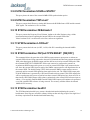
Introduction
1.1 Overview
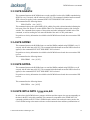
The Jackson Labs Technologies, Inc. RCM Reference board is a ruggedized, ultra-low-phase-noise
10MHz/100MHz crystal oscillator reference. The RCM Reference combines two low-g ovenized
crystal oscillators, power supplies, power filters, two isolated +20.5dBm RF output amplifiers, and
optional external 10MHz and 1PPS reference inputs on a 2.0 x 4.0 x 1.0 inch PCB board.
The RCM Reference board can be locked to either an external 10MHz signal or an external 1PPS
signal and has auto-switching capability from 10MHz lock to 1PPS lock as a fall-back in case the
external 10MHz reference is removed or fails. The unit will lock to within better than +/-500ps to the
external 10MHz reference typicallly with a <1.5Hz loop bandwidth, or to within +/-10ns to the
external 1PPS reference (rms/1-sigma) after 24 hours of locking when in 1PPS-locking mode. In the
absence of either external reference, the RCM Reference board will have a drift stability of better
than 0.5ppb per day long-term.
The use of a 10MHz double-oven OCXO and a single-oven 100MHz OCXO that is phase-locked to
the 10MHz OCXO provides better close-in phase noise performance, lower g-sensitivity, much
lower thermal sensitivity, and significantly improved holdover stability than the 100MHz OCXO can
provide by itself. The RCM reference achieves a phase noise performance of -100dBc/Hz at 10Hz
offset, and -130dBc/Hz at 100Hz offsets from the 100MHz carrier, and noise floors of -172dBc/Hz at
1MHz offset typically. The 10MHz CMOS output achieves -95dBc/Hz at 1 Hz offset, and
-130dBc/Hz at 10Hz offset typically when 1PPS locked. An exceptional low-g sensitivity of only
0.3ppb per g per axis allows operation in moving platforms and provides good vibration-noise
rejection. Allan Deviations of 2E-012 at 1s, and 2E-012 over 3 hours are possible when locked to
noisy external 1PPS references such as GPS receivers.
The unit also provides 1PPS outputs and inputs, and can be phase synchronized with less than 1ns
unit-to-unit uncertainty typically. The RCM Reference operates from a single +12V supply,
consumes less than 0.39A steady-state current, and operates from -45C to +85C.
The RCM Reference allows four operating modes:
1) 10MHz Synchronized. In this mode the unit phase-locks to an external 10MHz Sine Wave or
CMOS reference with a sub 1.5Hz loop bandwidth. The unit thus can operate as a phase noise filter
while still providing the Allan Deviation (ADEV) performance of the reference source
2) 1PPS Synchronized. In this mode the unit uses a field-proven loop algorithm to lock to an
external (noisy) 1PPS reference such as GPS receivers can provide. Loop Time Constants of 10’s of
seconds to 1000’s of seconds can be selected to filter out 1PPS noise such as GPS sawtooth noise.
© 2014 Jackson Labs Technologies, Inc.
1
RCM Reference User Manual
Please note that the unit can automatically switch to 1PPS sync-mode if the external 10MHz
reference fails or is disconnected.
3) Free-Running operation. No external references are attached or required. This stand-alone mode
allows operation with crystal-aging compensation via software loop, and drift of down to 0.1ppb over
the first day, and a maximum drift of 0.5ppb long-term.
4) Holdover Mode. This mode is identical to mode 3) and is automatically entered in case the unit
stops receiving any external 10MHz or 1PPS reference input signals.
The board includes an RS-232 serial control port for NMEA and SCPI communication, a 32bit
processor that runs a Real Time OS, one CMOS-5V 10MHz output, two 100MHz +20.5dBm outputs,
one 3.3V 1PPS CMOS output phase synchronized to an optional 1PPS input signal, a 10MHz
external reference input, and precision voltage references and DACs.
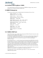
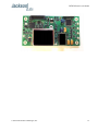
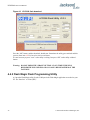
Figure 1.1
RCM 10MHz and 100MHz Reference
1.2 General Safety Precautions
The following general safety precautions must be observed during all phases of operation of this
instrument. Failure to comply with these precautions or with specific warnings elsewhere in this
manual violates safety standards of design manufacture, and intended use of the instrument. Jackson
Labs Technologies, Inc. assumes no liability for the customer’s failure to comply with these
requirements.
1.2.1 Antenna Lightning Protector
For units that use external GPS receivers as the 1PPS reference, always use a UL approved and
properly installed GPS Antenna Lightning protector on the coaxial GPS antenna feed to prevent
damage, injury, and/or death in case of a lightning strike.
1.2.2 Grounding
To avoid damaging the sensitive electronic components in the RCM Reference always make sure to
discharge any built-up electrostatic charge to a good ground source, such as power supply ground.
This should be done before handling the circuit board or anything connected to it.
2
© 2014 Jackson Labs Technologies, Inc.
RCM Reference User Manual
1.2.3 Power Connections
Make sure to connect the DC power to the device following the polarity indicated in Section 2.1 . The
power-pins are diode-protected and will not be damaged if the +12V power input wires are reversed.
1.2.4 Environmental Conditions
This instrument is intended for indoor use. It is designed to operate at a maximum relative
non-condensing humidity of 95% and at altitudes of up to 50,000 meters. Refer to the specifications
tables for the ac mains voltage requirements and ambient operating temperature range.
© 2014 Jackson Labs Technologies, Inc.
3
RCM Reference User Manual
4
© 2014 Jackson Labs Technologies, Inc.
RCM Reference User Manual
Quick-Start
Instructions
2.1 Powering Up the Unit
To operate the unit, simply follow these two steps:
1) If an external 10MHz reference source is to be used, then connect a 10MHz Sine Wave
reference signal to connector J3 (10MHz REF IN). The signal can range from +7dBm to
+15dBm. Or alternatively connect a 3.3V or 5V 1PPS signal with 50ms max duty cycle to
connector J2 (1PPS IN). Please note the 1PPS input is DC-terminated with a 50 Ohms
resistor to ground
2) Connect +12V (+/-1V) DC Power to J1 pins 3 and 4 on the unit, and ground to pins 1 and
2 of J1
=> The unit will consume up to 12W (1A) of power during oscillator warmup
Please note that the unit can operate as a highly-stable and accurate reference source by itself
in the absence of an external 1PPS or 10MHz reference input.
The unit will now lock to the external 10MHz or 1PPS signal (Red LED D1 is blinking when a 1PPS
reference or 10MHz reference is being received) and will indicate proper lock and no events pending
when the Green LED D1 goes on. Once the green LED D1 is on, the unit will output 10MHz with
significantly better than 1ppb frequency accuracy to the external reference.
The unit will lock to an external 10MHz reference within less than 2 seconds typically
once the OCXO has warmed-up after power-on, which typically takes less than 4
minutes at room temperature. The unit will take up to 1 hour to light up the Green LED
when locked to only the external 1PPS input. By default the unit prioritizes the 10MHz
reference input over the external 1PPS input.
Lock to the external 10MHz reference is indicated by a bright, solid Green light on
LED D13. Lock of the internal 100MHz OCXO to the internal 10MHz OCXO is
indicated by a bright, solid light on LED D23. During OCXO warmup, these LED’s
© 2014 Jackson Labs Technologies, Inc.
5
RCM Reference User Manual
will blink quickly, and the blinking will slow down as the OCXO approaches lock, then
light up continuously once lock is achieved. The 10MHz LOCK LED D13 and the
10MHz Input Sense LED D18 will not light up in the absence of an external 10MHz
reference signal.
Connect a terminal program (TeraTerm is recommended) to the unit via the RS-232 serial connector
pins 8 and 10 on connector J1 with 115.2KB 8N1 settings and no flow-control.
Try some of these SCPI commands:
help?
syst:stat?
diag?
sync?
meas?
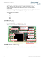
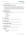
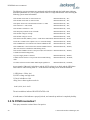
2.1.1 PCB Photos
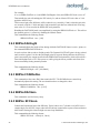
The RCM Reference PCB is shown in Figure 2.1.
Figure 2.1
RCM Reference 10MHz/100MHz PCB
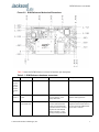
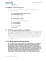
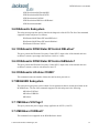
2.1.2 Mechanical Drawings
The following drawings show the mechanical dimensions and the pinout of the RCM Reference
PCB:
6
© 2014 Jackson Labs Technologies, Inc.
RCM Reference User Manual
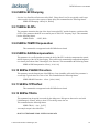
Figure 2.2
RCM Reference Mechanical Dimensions
Table 2.1shows the RCM Reference revision 1.0 hardware pin descriptions
Table 2.1 RCM Reference hardware connectors
Ref
Name
Function
Specification
Description
J1 Pins:
1,2,5,6,9,
11,12,13,
15,17,18,
19,21,23,
25,27,29,
30
GROUND
GROUND
GROUND
GROUND
J1 Pin 3
and Pin 4
+12V Prime
Power
Prime Power
+12V DC, +/-1V, <+/-50mV AC,
1A during warmup, <0.4A
steady state at 25C
DC +12V Power Input.
Reverse-Polarity protected
J1 Pin 7
1PPS CMOS
3.3V OUTPUT #2
Secondary 1PPS output
3.3V LVCMOS, <1ns rise-time.
50 Ohms series-terminated
output, do not end-terminate
signal with less than 1K Ohms,
aligned to J2 1PPS external
reference to within +/-2.5ns
typically. 20.48us pulse width.
1PPS output signal, rising-edge
aligned to external 1PPS reference,
or driven by internal 10MHz OCXO
phase when in holdover
© 2014 Jackson Labs Technologies, Inc.
7
RCM Reference User Manual
J1 Pin 8
RS-232 TX
RS-232 transmit pin
RS-232 level output
RS-232 transmit output from the
RCM module. Generates SCPI and
NMEA output strings
J1 Pin 10
RS-232 RX
RS-232 receive pin
RS-232 level input
RS-232 receive input to the RCM
module. Accepts SCPI commands
J1 Pin 14
RESET#
Reset input signal
Pulled to +3.3V internally by
4.7K Ohms resistor, pull to
ground (open collector pull) to
assert system reset
Pulling this pin to ground through a
switch or open-collector output will
reset the RCM module internal
microprocessor
J1 Pin 16
ISP#
In Circuit Programming
Enable pin
Pulled to +3.3V internally by
4.7K Ohms resistor, pull to
ground (open collector pull)
during reset or during power-up
to switch the microprocessor
into In System Programming
mode for Flash memory
upgrade of the firmware
Pulling this pin to ground through a
switch or open-collector output during
power-on or during reset will place
the internal microprocessor into In
System Flash Firmware Update
mode (see chapter 4 for details)
J1 Pin 20
1PPS OUTPUT
and LOCK OK
Built-In-Self-Test
(BIT)
1PPS output sense,
Lock and Event#
indicator
3.3V LVCMOS
3.3V: Unit Locked to reference, 1PPS
output is not damaged, and no
events are pending
PLL OK BIT
10MHz and 100MHz
PLL OK indicator
J1 Pin 22
0V: Hardware or software Event is
pending (events can be queried via
the sync:health? command)
3.3V LVCMOS
3.3V: 10MHz PLL (if in external
10MHz REF-IN mode) and 100MHz
PLL are locked and healthy
0V: 10MHz or 100MHz PLL has
failed to lock
J1 Pin 24
10MHz REF IN
Sense BIT
Senses 10MHz external
Reference
3.3V LVCMOS
3.3V: External 10MHz Ref Input is
receiving a high-frequency AC signal
(AC signals >1MHz will be detected)
0V: No AC signal detected on
external 10MHz Ref Input
J1 Pin 26
1PPS REF IN
Sense BIT
Senses 1PPS external
Reference
3.3V LVCMOS
3.3V: External 1PPS Ref Input is
receiving a 1Hz reference signal
0V: No external 1PPS Ref Input
detected
J1 Pin 28
Power Supply
Failure Sense BIT
Senses failure in internal
power supplies
3.3V LVCMOS
3.3V: Internal Power Supplies are
operating
0V: One or more internal Power
Supplies has a failure
J3
8
10MHz REF
INPUT
10MHz Sine Wave
Reference Input
10MHz +/-4Hz, +5dBm to
+17dBm (+22dBm damage
level), 50 Ohms terminated
10MHz Reference Input, the internal
OCXO’s, 1PPS counter, and the
microprocessor are synchronized to
this reference.
© 2014 Jackson Labs Technologies, Inc.
RCM Reference User Manual
J7
10MHz Output
Low-Phase-Noise
10MHz OCXO output
DC-coupled, 5V CMOS, 50
Ohms series-terminated, do not
end-terminate signal with less
than 1K Ohms
Ultra Low Phase Noise 10MHz
reference output from internal
Double-Oven 10MHz OCXO,
phase-locked to external 10MHz
reference or external 1PPS reference
J4
1PPS CMOS
3.3V OUTPUT #1
Primary 1PPS output
3.3V LVCMOS, <1ns rise-time.
50 Ohms series-terminated
output, do not end-terminate
signal with less than 1K Ohms,
aligned to J2 1PPS external
reference to within +/-2.5ns
typically. 20.48us pulse width
1PPS output signal, rising-edge
aligned to external 1PPS reference,
or driven by internal 10MHz OCXO
phase when in holdover
J2
1PPS INPUT
1PPS External
Reference input
1PPS pulse, 0V to 5V (max),
maximum on-duty-cycle 50ms,
DC-terminated to ground via 50
Ohms resistor
1PPS Reference Input. The 1PPS
outputs are rising-edge
phase-aligned to this input signal
within three seconds to better than
+/-2.5ns typically
J5
100MHz Output
#1
100MHz Sine Wave
Output
AC-coupled,100MHz Sine
Wave, +20.5dBm +2dB, -0.5dB,
terminate with 50 Ohms,
Harmonics <50dBc, Spurious
<80dBc, +/-15V DC max
allowed
100MHz Sine Wave output,
phase-locked to 10MHz internal
OCXO
J6
100MHz Output
#2
100MHz Sine Wave
Output
AC-coupled, 100MHz Sine
Wave, +20.5dBm +2dB, -0.5dB,
terminate with 50 Ohms,
Harmonics <50dBc, Spurious
<80dBc, +/-15V DC max
allowed
100MHz Sine Wave output,
phase-locked to 10MHz internal
OCXO
2.1.3 Notes on Signal Interfacing
The external 1PPS input reference is gated to reduce the possibility of spurious pulses causing a
delinquent phase-shift of the 1PPS output signal when the 1PPS reference cable is disconnected for
example. Once a 1PPS phase alignment has been achieved after an initial 3 pulses are received, the
unit will gate-disable the 1PPS input connector for about 1280ns less than exactly one second. This
prevents the problem of disconnecting of the 1PPS coax cable during the pulse high-time of the
external 1PPS pulse to generate spurious 1PPS pulses in the unit due to cable connector bounce.
Once the unit has gated the input for slightly less than 0.999,999 seconds, external pulses are once
again allowed to re-synchronize the internal 1PPS counter. The internal 1PPS counter is clocked by
the 100MHz output multiplied by 2x, so it internally runs at 200MHz with a 5ns cycle time. This
allows synchronization to the external 1PPS signal to within +/-2.5ns uncertainty, and removes all
errand pulses with more than -1280ns offset to the previous 1PPS input.
Do not terminate the 10MHz CMOS and 1PPS CMOS signals with impedances less than 1K Ohms,
these signals are properly series-terminated with 50 Ohms and can thus drive long 50 Ohms coax
cables with no over/under-shoot or ringing.
© 2014 Jackson Labs Technologies, Inc.
9
RCM Reference User Manual
The unit will immediatly try to lock to an external 10MHz reference input if such a signal is applied
after power-on. It will be able to achieve lock to the external 10MHz signal within typically 4
minutes after power-on at 25C, and if the 10MHz signal is within +/-4 Hz or better of absolute
10MHz. In the absence of an external 10MHz reference signal, the unit will wait 7 minutes after
power-on, then locking to the external 1PPS reference signal will begin if an external 1PPS input
signal is present. The unit will require 12 to 15 minutes typically to achieve lock to within 0.2ppb
frequency accuracy. The external 1PPS signal is also used to synchronize the 1PPS output, and if the
1PPS external reference is removed the unit will produce a 1PPS output signal generated by the
100MHz output signal divided by exactly 100,000,000 and for a length of 20.48us, and will remain
phase aligned to the external 1PPS reference within the drift of the internal 10MHz DOCXO.
In the absence of both a 10MHz and 1PPS external reference inputs the unit will go into
high-stability holdover mode during which the internal 10MHz DOCXO is compensated by a
software aging-compensation algorithm. The unit will continue to produce very stable 10MHz,
100MHz and 1PPS output signals with typically less than 0.5ppb long-term drift per day. In the
absence of any 1PPS external reference pulses the unit will randomly align its 1PPS output to exactly
100,000,000 cycles of the 100MHz output for a length of 20.48us.
2.1.4 Coaxial Connectors
The RF connectors of the RCM Reference are compatible to the Samtec MH1RP, and Amphenol
A-1JB series of connectors, and sample mating cables can be purchased at www.digkey.com with
part number: MH113-MH1RP-01BJ1-0152
2.1.5 Main Power and Control Connector
Power is applied to the RCM Reference board through the 30-pin Samtec connector J1. This
connector has Samtec PN: TFM-115-01-S-D-WT, and is compatible to Samtec cable harnesses PN:
SFSDT-15-30-G-10.00-DR-NDX and others. The connector uses mechanical retention latches.
The unit is powered from a +11.0V to +13.0V DC source, with +12.0V nominal voltage. The current
is typically less than 0.39A at 12V at +25C ambient steady-state, and ~1A during OCXO warmup at
12.0V. Connect a clean +12V power supply to pins 3 and 4 of J1, and ground to pins 1 and 2 of J1.
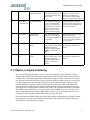
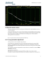
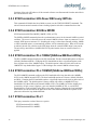
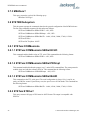
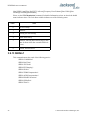
2.1.6 Typical Phase Noise Performance
The following figure shows a typical Phase Noise performance plot when the unit is in holdover
mode:
10
© 2014 Jackson Labs Technologies, Inc.
RCM Reference User Manual
RCM Reference Typical 100MHz Phase Noise in holdover mode
2.2 Remote serial control
The unit is controlled via the RS-232 serial port at 115200 baud, 8N1. Other Baud Rates can be set
via SCPI commands.
Attach the RCM Reference unit to your PC’s Hyperterminal, the optional GPSCon software package
(see Chapter 5 of this manual), or a third-party freeware Windows-based application program called
Z38xx. This program is available on the Jackson Labs Technologies, Inc. website under the
following URL as a free download:
http://www.jackson-labs.com/assets/uploads/main/Z38XX.zip
2.2.1 Loop parameter adjustment
All loop parameters can be controlled via the serial port.
Loop parameters are optimized for the OCXO on the board when locking to the external 1PPS
reference , and changing the factory settings may result in the unit’s performance to deteriorate.
These loop parameters do not affect the loop behavior when the unit is locking to the external 10MHz
reference input.
The commands to control the loop parameters are part of the servo? command. See also the SERVO
Subsystem section below.
The individual commands are:
EFC Scale: this is the proportional gain of the PID loop. Higher values will give quicker
convergence, and faster locking of the GPS time (lower loop time constant), lower values give less
© 2014 Jackson Labs Technologies, Inc.
11
RCM Reference User Manual
noise. Values between 0.7 (good double oven OCXO) and 6.0 (simple single-oven OCXO) are
typical.
EFC Damping: overall IIR filter time constant. higher values increase loop time
constant. Jackson Labs Technologies, Inc. typically uses values between 10 to 50. Setting this value
too high may cause loop instability.
Phase compensation: this is the Integral part of the PID loop. This corrects phase offsets between
the RCM Reference 1PPS signal and the UTC 1PPS signal as generated by the external 1PPS
reference. Set higher values for tighter phase-following at the expense of frequency stability. Typical
values range from 4 - 30, 25 being the default. Setting this value too high may cause loop instability.
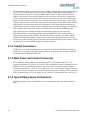
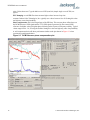
A well-compensated unit will show performance similar to the plot shown in Figure 2.3 when
experiencing small perturbations:
Figure 2.3
12
RCM Reference phase compensation plot
© 2014 Jackson Labs Technologies, Inc.
RCM Reference User Manual
SCPI-Control Quick
Start Instructions
3.1 Introduction
The SCPI (Standard Commands for Programmable Instrumentation) subsystem is accessed via the
TTL or USB serial interfaces and a terminal program. By default the terminal settings are 115200,
8N1, no flow-control.
There are a number of commands that can be used as listed below. Most of these are identical or
similar to Symmetricom 58503A commands. To get a listing of the available commands, send the
HELP? query. This will return a list of all the available commands for the RCM Reference.
Additional information regarding the SCPI protocol syntax can be found on the following web site:
http://www.scpiconsortium.org
Please refer to the document SCPI-99.pdf for details regarding individual SCPI command
definitions. A basic familiarity with the SCPI protocol is recommended when reading this chapter.
3.2 General SCPI Commands
3.2.1 Quick Start Commands
For a quick start, try the following SCPI serial port commands:
help?
sync?
meas?
diag?
*IDN?
3.2.2 *IDN?
This query outputs an identifying string. The response will show the following information:
© 2014 Jackson Labs Technologies, Inc.
13
RCM Reference User Manual
<company name>, <model number>, <serial number>, <firmware revision>
3.2.3 HELP?
This query returns a list of the commands available for the RCM Reference.
3.3 GPS Subsystem
The GPS subsystem is only partially supported on the RCM Reference since it does not have a GPS
receiver. It does however support NMEA time and date related commands with the aid of the user
manually setting time and date once after power-on. The internal RTC will maintain time and date
with the stability of the internal 10MHz OCXO, and NMEA commands can be enabled to output
time and date on the serial ports.
3.3.1 NMEA Support
No navigation information is available on the NMEA output, but time and date can be maintained
and transmitted on the relevant NMEA sentences once set by the user using the GPS:INIT:TIME and
GPS:INIT:DATE commands.
The NMEA time and date outputs are synchronized to the rising edge of the incomming 1PPS
reference. Please note that without an initial 1PPS reference input pulse the NMEA output
strings will not be generated unless the option SYNC:OUT:RESET:1PPS ON command has
been sent to enable the unit to generate asynchronous internal 1PPS pulses for the NMEA
engine.
Once enabled, RCM Reference will send out information on the TTL and USB serial transmit pin
automatically every N seconds. All incoming serial commands are still recognized by RCM
Reference since the serial interface transmit and receive lines are completely independent of one
another.
Once set, the following two commands will be stored in NV memory, and generate output
information even after power to the unit has been cycled.
3.3.2 GPS:GPGGA
This command instructs the RCM Reference to send the NMEA standard string $GPGGA every N
seconds, with N in the interval [0,255]. The command is disabled until an external 1PPS reference is
applied, or the command SYNC:OUT:1PPS:RESET ON is selected.
This command has the following format:
GPS:GPGGA <int> [0,255]
No position or velocity information is available as the RCM Reference board does not contain a GPS
receiver.
14
© 2014 Jackson Labs Technologies, Inc.
RCM Reference User Manual
3.3.3 GPS:GGASTat
This command instructs the RCM Reference to send a modified version of the NMEA standard string
$GPGGA every N seconds, with N in the interval [0,255]. The command is disabled until an external
1PPS reference is applied, or the command SYNC:OUT:1PPS:RESET ON is selected.
This command has the following format:
GPS:GGASTat <int> [0,255]
This command replaces the regular NMEA GGA validity flag with a decimal number indicating the
lock-state of the unit. Please see section SERVo:TRACe for a detailed description of the lock state
variable. The command allows capture of the position and other information available in the GGA
command, as well as tracking the lock state and health of the unit’s OCXO performance.
No position or velocity information is available as the RCM Reference board does not contain a GPS
receiver.
3.3.4 GPS:GPRMC
This command instructs the RCM Reference to send the NMEA standard string $GPRMC every N
seconds, with N in the interval [0,255]. The command is disabled until an external 1PPS reference is
applied, or the command SYNC:OUT:1PPS:RESET ON is selected.
No position or velocity information is available as the RCM Reference board does not contain a GPS
receiver.
This command has the following format:
GPS:GPRMC <int> [0,255]
3.3.5 GPS:GPZDA
This command instructs the RCM Reference to send the NMEA standard string $GPZDA every N
seconds, with N in the interval [0,255]. The command is disabled until an external 1PPS reference is
applied, or the command SYNC:OUT:1PPS:RESET ON is selected.
No position or velocity information is available as the RCM Reference board does not contain a GPS
receiver.
This command has the following format:
GPS:GPZDA <int> [0,255]
3.3.6 GPS:INITial:DATE <yyyy,mm,dd>
In order to have the RCM Reference generate valid time and date outputs, the user must manually set
the date in the RTC using this command. This command is compatible to the PTIME:OUT ON
command available on the JLT CSAC GPSDO boards, and the unit can thus be auto-synced to the
CSAC GPSDO acting as the master reference to allow automatic time and date synchronization of
© 2014 Jackson Labs Technologies, Inc.
15
RCM Reference User Manual
these units to each other. The internal RTC is driven by the highly stable OCXO 10MHz signal, and
thus has very high accuracy.
3.3.7 GPS:INITial:TIME <hour,min,sec>
In order to have the RCM Reference generate valid time and date outputs, the user must manually set
the time in the RTC using this command. This command is compatible to the PTIME:OUT ON
command available on the JLT CSAC GPSDO boards, and the unit can thus be auto-synced to the
CSAC GPSDO acting as the master reference to allow automatic time and date synchronization of
these units to each other. The internal RTC is driven by the highly stable OCXO 10MHz signal, and
thus has very high accuracy.
3.4 PTIME Subsystem
The PTIME subsystem regroups all the commands related to the management of the time.The list of
the commands supported is the following:
PTIMe:DATE?
PTIMe:TIME?
PTIMe:TIME:STRing?
PTIMe:TINTerval?
PTIME?
3.4.1 PTIMe:DATE?
This query returns the current calendar date. The year, month, and day are returned.
3.4.2 PTIMe:TIME?
This query returns the current 24-hour time. The hour, minute, and second is returned.
3.4.3 PTIMe:TIME:STRing?
This query returns the current 24-hour time suitable for display (for example, 13:24:56).
3.4.4 PTIMe:TINTerval?
This query is equivalent to the command SYNChronization:TINTerval
3.4.5 PTIME?
This query returns at once the result of the three following queries:
PTIME:DATE?
PTIME:TIME?
16
© 2014 Jackson Labs Technologies, Inc.
RCM Reference User Manual
PTIME:TINTerval?
3.5 SYNChronization Subsystem
This subsystem regroups the commands related to the synchronization of the RCM Reference with
the external 1PPS or 10MHz reference. The list of the commands supported for this subsystem is the
following:
SYNChronization:SOURce:MODE [10MHZ|1PPS|AUTO]
SYNChronization:SOURce:STATE?
SYNChronization:HOLDover:DURation?
SYNChronization:HOLDover:STATe?
SYNChronization:HOLDover:INITiate
SYNChronization:HOLDover:RECovery:INITiate
SYNChronization:OUTput:1PPS:RESET [ON|OFF]
SYNChronization:TINTerval?
SYNChronization:IMMEdiate
SYNChronization:FEEstimate?
SYNChronization:LOCKed?
SYNChronization?
3.5.1 SYNChronization:HOLDover:DURation?
This query returns the duration of the present or most recent period of operation in the holdover and
holdover processes. This is the length of time the reference oscillator was not locked to the external
1PPS or 10MHz reference, and thus “coasting”. The time units are seconds. The first number in the
response is the holdover duration. The duration units are seconds, and the resolution is 1 second. If
the Receiver is in holdover, the response quantifies the current holdover duration. If the Receiver is
not in holdover, the response quantifies the previous holdover. The second number in the response
identifies the holdover state. A value of 0 indicates the Receiver is not in holdover; a value of 1
indicates the Receiver is in holdover.
3.5.2 SYNChronization:HOLDover:INITiate
The SYNC:HOLD:INIT and SYNC:HOLD:REC:INIT commands allow the user to manually enter
and exit the holdover state, even while external reference signals are still being properly received.
This command only affects the external 1PPS tracking mode, and is inactive when in external
10MHz tracking mode. This forced-holdover allows the unit to effectively disable reference locking,
while still keeping track of the state of the 1PPS output in relation to the 1PPS signal as generated by
the external reference. When the unit is placed into forced-holdover with this command, the unit will
indicate the time interval difference between the 1PPS output and the external 1PPS or 10MHz
reference signal by using the SYNC:TINT? command. This allows the user to see the OCXO drift
when not locked to the external reference for testing purposes. All other frequency-disciplining
© 2014 Jackson Labs Technologies, Inc.
17
RCM Reference User Manual
functions of the unit will behave as if the external reference was disconnected from the unit while in
this forced-holdover state.
3.5.3 SYNChronization:HOLDover:RECovery:INITiate
This command will disable the forced holdover state (see the SYNC:HOLD:INIT command). The
unit will resume normal external reference locking operation after this command has been sent.
3.5.4 SYNChronization:SOURce:MODE
SYNChronization:SOURce:MODE [10MHZ | 1PPS | AUTO]
The SOURce:MODE command selects the synchronization source for the internal 10MHz ovenized
oscillator. The source is selected between an external 10MHz reference input on connector J3 or an
external 1PPS input on connector J2. Switching the source is either done manually with the 10MHz
or 1PPS command options, or automatically with the AUTO command option. When AUTO mode
is enabled, the unit only switches to the 1PPS input when the external 10MHz input is not present.
The unit will go into holdover (10MHz DOCXO flywheel mode) when no external reference is
applied.
3.5.5 SYNChronization:PLL:10MHZ [NARrow:MEDium:WIDe]
The PLL:10MHZ command configures the PLL bandwidth. The three bandwidth options are Narrow
(default), Medium and Wide. Changing the PLL bandwidth can have a significant impact on the
close-in phase noise of the 100MHz output. The default option is Narrow which will result in a
10MHz PLL loop bandwidth of approx 1.5Hz locking to the external 10MHz reference input.
3.5.6 SYNChronization:PLL:100MHZ [NARrow:MEDium:WIDe]
The PLL:100MHZ command configures the PLL bandwidth of the loop that locks the 100MHz
OCXO to the 10MHz internal OCXO. The three bandwidth options are Narrow (default), Medium
and Wide. Changing the PLL bandwidth can have a significant impact on the close-in phase noise of
the 100MHz output. The default option is Narrow which will result in a 100MHz PLL loop
bandwidth of less than 50Hz to the internal 10MHz OCXO. The 10MHz OCXO has slightly less
g-sensitivity (0.3ppb versus 0.5ppb per g per axis) than the 100MHz OCXO, so a wider PLL
bandwidth may result in slightly lower phase noise under vibration. Changing the loop bandwidth
from narrow to wide also lowers the phase noise above the bandwidth limit at the expense of the
phase noise below the loop bandwidth limit.
3.5.7 SYNChronization:PLL?
This query returns the results of these two queries:
SYNChronization:PLL:10MHZ?
SYNChronization:PLL:100MHZ?
18
© 2014 Jackson Labs Technologies, Inc.
RCM Reference User Manual
3.5.8 SYNChronization:SOURce:STATE?
This query shows the state of the external 10MHz/1PPS synchronization option.
3.5.9 SYNChronization:TINTerval?
This query returns the difference or timing shift between the RCM Reference 1PPS and the external
1PPS signals. The resolution is 1E-10 seconds.
3.5.10 SYNChronization:FEEstimate?
This query returns the Frequency Error Estimate, similar to the Allan Variance using a 1000s
measurement interval and comparing the internal 1PPS to the external 1PPS offset.
Values less than 1E-012 are below the noise floor, and are not significant.
3.5.11 SYNChronization:LOCKed?
This query returns the lock state (0=OFF, 1=ON) of the PLL controlling the internal 10MHz
oscillator.
3.5.12 SYNChronization:OUTput:1PPS:RESET [ON|OFF]
This command allows the generation of the NMEA output sentences upon power-on without an
external 1PPS reference being connected to the unit. By default the unit does not generate an internal
1PPS pulse that triggers the NMEA output until the unit has received an external 1PPS pulse. With
the command SYNC:OUT:1PPS:RESET ON the unit can now be configured to generate an
asynchronous NMEA output after power-on even if an external 1PPS input is not connected to the
unit. Once the external 1PPS signal is applied, the NMEA output sentences will align themselves to
the external 1PPS. The default setting is OFF which means the NMEA output sentences are not
generated until an external 1PPS signal has been applied to the unit. The CMOS 1PPS output pulse
of the RCM Reference is generated by a PLD and not under software control. This 1PPS output pulse
will be asynchronous after power-on until at least three external 1PPS pulses have been received. At
that time the 1PPS CMOS output will be phase-synchronized to the external 1PPS reference input to
within +/-2.5ns typically. Both the NMEA and the CMOS 1PPS outputs will continue to be generated
even if the external 1PPS reference is being removed. The accuracy will then follow the internal
10MHz OCXO accuracy.
3.5.13 SYNChronization:health?
The SYNChronization:health? query returns a hexadecimal number indicating the system’s
health-status. Error flags are encoded in a binary fashion so that each flag occupies one single bit of
the binary equivalent of the hexadecimal health-status flag.
© 2014 Jackson Labs Technologies, Inc.
19
RCM Reference User Manual
The following system parameters are monitored and indicated through the health-status indicator.
Individual parameters are ‘ored’ together which results in a single hexadecimal value encoding the
following system status information:
If the OCXO coarse-DAC is maxed-out at 255
HEALTH STATUS |= 0x1;
If the OCXO coarse-DAC is mined-out at 0
HEALTH STATUS |= 0x2;
If the phase offset to the external 1PPS reference is >250ns
HEALTH STATUS |= 0x4;
If the run-time is < 300 seconds
HEALTH STATUS |= 0x8;
If the OCXO is in holdover > 60s
HEALTH STATUS |= 0x10;
If the Frequency Estimate is out of bounds
HEALTH STATUS |= 0x20;
If the OCXO voltage is too high
HEALTH STATUS |= 0x40;
If the OCXO voltage is too low
HEALTH STATUS |= 0x80;
If the short-term-drift (ADEV @ 100s) > 100ns when 1PPS-locked HEALTH STATUS |= 0x100;
For the first 7 minutes after a phase-reset, or a coarsedac change
HEALTH STATUS |= 0x200;
If the 100MHz PLL is not locked to the internal 10MHz OCXO
HEALTH STATUS |= 0x400;
If the 10MHz PLL is not locked to the external 10MHz reference
(this error status bit is disabled in 1PPS locking mode)
HEALTH STATUS |= 0x2000;
If the external 10MHz reference is not present (this error status bit HEALTH STATUS |= 0x4000;
is disabled in 1PPS locking mode)
If a power supply failure is detected
HEALTH STATUS |= 0x8000;
If 1PPS external reference is not present when in 1PPS locking
mode
HEALTH STATUS |= 0x10000;
If a failure is detected in the CMOS 1PPS output signal driver
HEALTH STATUS |= 0x20000;
As an example, if the unit is in holdover, and the OCXO voltage is too high, and the 1PPS phase
offset while in 1PPS locking mode is > 250ns then the following errors would be indicated:
1) 1PPS phase > 250ns: 0x4
2) OCXO voltage too high: 0x40
3) Unit is in holdover: 0x10
‘Oring’ these values together results in:
0x40 | 0x10 | 0x4 = 0x54
The unit would thus indicate: HEALTH STATUS: 0x54
A health status of 0x0 indicates a properly locked, and warmed-up unit that is completely healthy.
3.5.14 SYNChronization?
This query returns the results of these four queries:
20
© 2014 Jackson Labs Technologies, Inc.
RCM Reference User Manual
SYNChronization:SOURce:MODE?
SYNChronization:SOURce:STATE?
SYNChronization:LOCKed?
SYNChronization:HOLDover:DURation?
SYNChronization:health?
3.6 DIAGnostic Subsystem
This subsystem regroups the queries related to the diagnostic of the OCXO.The list of the commands
supported for this subsystem is as follows:
DIAGnostic:ROSCillator:EFControl:RELative?
DIAGnostic:ROSCillator:EFControl:ABSolute?
DIAGnostic:LIFetime:COUNt?
3.6.1 DIAGnostic:ROSCillator:EFControl:RELative?
This query returns the Electronic Frequency Control (EFC) output value of the internal reference
oscillator. It returns a percentage value between -100% to +100%.:
3.6.2 DIAGnostic:ROSCillator:EFControl:ABSolute?
This query returns the Electronic Frequency Control (EFC) output value of the internal reference
oscillator. It returns a value in volts between 0 and 5 V
3.6.3 DIAGnostic:LIFetime:COUNt?
This command returns the number of hours the unit has been powered-on.
3.7 MEASURE Subsystem
This subsystem regroups the queries related of some parameters that are measured on-board on the
RCM Reference. The list of the commands supported for this subsystem is the following:
MEASure:VOLTage?
MEASure:CURRent?
MEASure?
3.7.1 MEASure:VOLTage?
This query returns the power supply voltage applied to the OCXO (~10.45V)
3.7.2 MEASure:CURRent?
This command is not supported on the RCM Reference board.
© 2014 Jackson Labs Technologies, Inc.
21
RCM Reference User Manual
3.7.3 MEASure?
This query returns the result of the following query:
MEASure:VOLTage?
3.8 SYSTEM Subsystem
This subsystem regroups the commands related to the general configuration of the RCM Reference.
The list of the commands supported for this subsystem follows:
SYSTem:COMMunicate:SERial:ECHO <ON | OFF>
SYSTem:COMMunicate:SERial:PROmpt <ON | OFF>
SYSTem:COMMunicate:SERial:BAUD <9600 | 19200 | 38400 | 57600 | 115200>
SYSTem:STATus?
SYSTem:FACToryReset ONCE
3.8.1 SYSTem:COMMunicate
3.8.1.1 SYSTem:COMMunicate:SERial:ECHO
This command enables/disables echo on TTL serial. This command has the following format:
SYSTem:COMMunicate:SERial:ECHO <ON | OFF>
3.8.1.2 SYSTem:COMMunicate:SERial:PROmpt
This command enables/disables the prompt “scpi>” on the SCPI command lines. The prompt must be
enabled when used with the software GPSCon. This command has the following format:
SYSTem:COMMunicate: SERial:PROmpt <ON | OFF>
3.8.1.3 SYSTem:COMMunicate:SERial:BAUD
This command sets the TTL serial speed. The serial configuration is always 8 bit, 1 stop bit, no
parity, no HW flow control. Upon Factory reset, the speed is set at 115200 bauds. This command has
the following format:
SYSTem:COMMunicate:SERial:BAUD <9600 | 19200 | 38400 | 57600 | 115200>
3.8.2 SYSTem:STATus?
This query returns a full page of GPS status in ASCII format. The output is compatible with
GPSCon.
22
© 2014 Jackson Labs Technologies, Inc.
RCM Reference User Manual
3.8.3 SYSTem:FACToryReset ONCE
This command applies the Factory Reset setting to the EEPROM. All aging, tempco, and user
parameters are overwritten with factory default values.
3.9 SERVO Subsystem
This subsystem regroups all the commands related to the adjustment of the servo loop:
SERVo:COARSeDac <int> [0,225]
SERVo:DACGain <int> [0.1,10000]
SERVo: EFCScale <float>[0.0 , 500.0]
SERVo:EFCDamping <float>[0.0 , 4000.0]
SERVo:SLOPe
<NEG | POS >
SERVo:TEMPCOmpensation <float> [-4000.0, 4000.0]
SERVo:AGINGcompensation <float> [-10.0, 10.0]
SERVo:PHASECOrrection <float> [-100.0, 100.0]
SERVo:1PPSoffset
<int> ns
SERVo:QUIet <ON | OFF>
SERVo:TRACe <int > [0,255]
SERVo:FASTlock <int> [1,20]
SERVo:FALEngth <int> [100,20000]
SERVo?
3.9.1 SERVo:FASTlock
The FASTlock feature is only available when operting in the 1PPS LOCK mode. It is not active when
locking to an external 10MHz reference input.
The FASTlock command enables the FASTLOCK mode, and sets its gain parameter. Fastlock works
by momentarily multiplying the EFCScale gain to a value determined by this SERVo:FASTlock
parameter. Gain values of 1x to 20x can be set, with a gain of 1x effectively disabling the
FASTLOCK feature.
By selecting gain values of >1, the PLL loop parameter Proportional gain (SERV:EFCscale) will be
increased after power on, thus increasing loop aggressiveness and improving lock PLL time. It is not
desirable to maintain a high loop gain for longer than necessary to lock the PLL since high loop gains
come at the expense of increased phase noise (reduced short term stability). The FASTLOCK
mechanism will automatically reduce the FASTLOCK gain over a period of time specified by the
SERVo:FALEngth command, during which time the FASTLOCK gain is slowly decreased from its
initial value to 1.0x.
Setting the FASTLOCK gain to 2 for example will result in the Proportional gain value stored in the
SERVo:EFCscale parameter to be multiplied by 2x initially after power on.
This dynamic gain is slowly reduced until the gain is back to 1.0x, the value stored in the
SERVo:EFCScale parameter.
© 2014 Jackson Labs Technologies, Inc.
23
RCM Reference User Manual
For example:
if we set SERVo:FASTlock to 2, and SERVo:FALEngth to 3600, and SERVo:EFCScale is set to 0.7
Then initially the unit will multiply the EFCscale by 2x, and an effective EFCscale value of 1.4 is
applied to the PLL loop.
This increased gain value difference will be reduced every second by 1/3600, so that the gain after
two seconds would be: 1.3998, until after 3600 seconds the gain has been reduced back to its long
term value of 0.70 as stored in the SERVo:EFCscale parameter.
Disabling the FASTLOCK mode is accomplished by setting the SERVo:FASTlock to 1. This will set
the dynamic gain to 1.0, effectively disabling the fastlock feature.
This command has the following format:
SERVo:FASTlock <int> [1,20]
3.9.2 SERVo:FALEngth
This command adjusts the length of time during which the FASTLOCK feature is active, please see
the command SERVo:FASTlock above.
It can be set from 100 seconds to 20.000 seconds. The Dynamic FASTLOCK gain is slowly reduced
until it reaches a gain of 1.0 after the FALEngth period of seconds. During this time the PLL loop
gain is increased by the amount specified in the SERVo:FASTlock parameter, which will result in a
faster initial phase lock to UTC after power-on, while giving the lowest possible noise floor (best
short term stability) during normal operation.
This command has the following format:
SERVo:FALEngth <int> [100,20000]
3.9.3 SERVo:COARSeDac
This command sets the coarse DAC that controls the EFC. The RCM Reference control loop
automatically adjusts this setting. The user should not have to change this value.
This command has the following format:
SERVo:COARSeDac <int> [0,225]
3.9.4 SERVo:DACGain
This command is used for factory setup.
3.9.5 SERVo: EFCScale
Controls the Proportional part of the PID loop. Typical values are 0.7 (double oven OCXO) to 6.0
(simple single oven OCXO). Larger values increase the loop control at the expense of increased noise
while locked. Setting this value too high can cause loop instabilities.
This command has the following format:
SERVo: EFCScale <float>[0.0 , 500.0]
24
© 2014 Jackson Labs Technologies, Inc.
RCM Reference User Manual
3.9.6 SERVo:EFCDamping
Set’s the Low Pass filter effectiveness of the DAC. Values from 2.0 to 50 are typically used. Larger
values result in less noise at the expense of phase delay.This command has the following format:
SERVo:EFCDamping <float>[0.0 , 4000.0]
3.9.7 SERVo:SLOPe
The parameter determines the sign of the slope between the EFC and the frequency variation of the
OCXO. This parameter should be set to match your OCXO’s EFC frequency slope. This command
has the following format:
SERVo:SLOPe
<NEG | POS >
3.9.8 SERVo:TEMPCOmpensation
This command is not supported on the RCM Reference board.
3.9.9 SERVo:AGINGcompensation
This parameter is a coefficient that represents the drift of the EFC needed to compensate the natural
drift in frequency of the OCXO due to aging. This coefficient is automatically computed and adjusted
over time by the Jackson Labs Technologies, Inc. firmware. This command has the following format:
SERVo:AGINGcompensation <float> [-10.0, 10.0]
3.9.10 SERVo:PHASECOrrection
This parameter sets the Integral part of the PID loop. Loop instability will result if the parameter is
set too high. Typical values are 10.0 to 30.0. This command has the following format:
SERVo:PHASECOrrection <float> [-100.0, 100.0]
3.9.11 SERVo:1PPSoffset
This command is not supported on the RCM Reference board.
3.9.12 SERVo:TRACe
This command sets the period in seconds for the debug trace. Debug trace data can be used with
Ulrich Bangert’s “Plotter” utility to show UTC tracking versus time etc.
This command has the following format:
SERVo:TRACe <int > [0,255]
An example output is described here:
08-07-31 373815 60685 -32.08 -2.22E-11 14 10 6 0x54
© 2014 Jackson Labs Technologies, Inc.
25
RCM Reference User Manual
[date][1PPS Count][Fine DAC][UTC offset ns][Frequency Error Estimate][Sats Visible][Sats
Tracked][Lock State][Health Status]
Please see the SYNChronization? command for detailed information on how to decode the health
status indicator values. The Lock State variable indicates one of the following states:
Value
State
0
OCXO warmup
1
Holdover
2
Locking (OCXO training)
4
[Value not defined]
5
Holdover, but still phase locked (stays in this
state for about 100s after external-1PPS lock
is lost)
6
Locked, and GPS active
3.9.13 SERVo?
This command returns the result of the following queries:
SERVo:COARSeDac?
SERVo:DACGain?
SERVo: EFCScale?
SERVo:EFCDamping?
SERVo:SLOPe?
SERVo:TEMPCOmpensation?
SERVo:AGINGcompensation?
SERVo:PHASECOrrection?
SERVo:1PPSoffset?
SERVo:TRACe?
26
© 2014 Jackson Labs Technologies, Inc.
RCM Reference User Manual
© 2014 Jackson Labs Technologies, Inc.
27
RCM Reference User Manual
28
© 2014 Jackson Labs Technologies, Inc.
RCM Reference User Manual
Firmware Upgrade
Instructions
4.1 Introduction
The following is a short tutorial on how to upgrade the RCM Reference firmware. Please follow the
instructions in-order to prevent corrupting the RCM Reference Flash, which may require reflashing
at the factory.
With some practice, the entire Flash upgrade can be done in less than five minutes, even though the
following seems like a fairly long list of instructions.
4.2 ISP Flash Loader Utility installation
There are two Flash loader utilities available to upgrade the RCM Reference firmware. You can
download the Philips LPC2000 utility from the Jackson Labs Technologies, Inc. website under the
Support tab:
http://www.jackson-labs.com/index.php/support
The Flash Magic utility is available for download on the Flash Magic website:
http://www.flashmagictool.com/
4.2.1 Philips LPC2000 Flash Utility
The first is the Philips LPC2000 utility version 2.2.3. Please note that some computers are known to
be incompatible with the LPC2000 flash utility. Preliminary investigations show Windows Media
Center and/or Centrino vPro processor systems to create download difficulties. Please use a different
computer if you experience problems such as the download breaking up in the middle of the transfer.
Or, alternatively, you may use the Flash Magic programming tool.
Please ensure that you have at least version 2.2.3 of the LPC2100 flash utility installed. Earlier
versions may not recognize the LPC2138 processor used on the RCM Reference boards.
© 2014 Jackson Labs Technologies, Inc.
29
RCM Reference User Manual
4.2.2 Flash Magic Flash Programming Utility
The second utility is the Flash Magic tool available on the Flash Magic website:
http://www.flashmagictool.com/
If the Philips LPC2000 tool doesn’t work, please use this one.
4.3 Putting the PCB into In-Circuit Programming (ISP) mode
Momentarily short-out the ISP# pin 16 of connector J1 to pin 18 (GROUND) of connector J1 of the
RCM Reference board to ground the ISP# pin during power-on. It may be useful to connect a
push-button to pin 16 and pin 18 of J1 to allow in-field firmware upgrades on the RCM Reference
PCB. Both LED’s should remain off, indicating the unit is properly placed into ISP mode. If the
LED’s light up after power-on, the unit is not in ISP mode.
4.4 Downloading the firmware
Download the latest version of RCM Reference firmware from the Jackson Labs Technologies, Inc.
support website and store it in a place that will be remembered. The file is in .hex format.
The unit needs to be connected to the computer’s RS-232 serial port prior to firmware download. The
RCM Reference is RS-232 level compatible.
4.4.1 Philips LPC2000 Flash Utility
A) Open the LPC2000 utility. Set the COM port in the LPC2000 application as needed on your PC.
B) Select the Baud Rate of the LPC2000 utility to be 38400 or slower. Faster Baud rates will not
work properly.
C) Press the “READ DEVICE ID” button, this should then show “LPC2138” in the DEVICE
window if the unit is communicating correctly to the application.
Warning: Make sure NOT(!) to press the “erase” button under any circumstances, this may
erase factory calibration data, and the unit will not operate and will have to be
returned to the factory. Pressing the “erase” button on the ISP utility will thus void
the warranty.
30
© 2014 Jackson Labs Technologies, Inc.
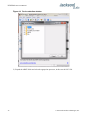
RCM Reference User Manual
Figure 4.1
LPC2000 flash utility
Please note that the “Use Baud Rate” setting needs to be set to 38400 Baud or less, it will not work
faster than 38400 Baud.
The “DEVICE” should show up as “LPC2138” after pressing “READ DEVICE ID”
Also, please point the “Filename” to the directory where you have stored the latest firmware hex file
that is to be downloaded.
D) Start the download by pressing “Upload to Flash” button. The following window should appear if
the correct COM port has been chosen etc.:
© 2014 Jackson Labs Technologies, Inc.
31
RCM Reference User Manual
Figure 4.2
LPC2000 flash download
Press the “OK” button, and the download should start. Sometimes the utility gets confused and this
process (from item 4.4 B) ) has to be tried several times.
It is not necessary to press “reset” as the utility is asking. Just press “OK” on the utility window’s
button.
Warning: DO NOT PRESS THE “ERASE” BUTTON AT ANY TIME! THIS WILL
RENDER THE PCB USELESS AND CAN ONLY BE RECOVERED AT THE
FACTORY!
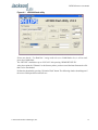
4.4.2 Flash Magic Flash Programming Utility
A) Open the Flash Magic utility. Set the COM port in the Flash Magic application as needed on your
PC. Set “Interface” to “None (ISP)”.
32
© 2014 Jackson Labs Technologies, Inc.
RCM Reference User Manual
Figure 4.3
Flash Magic utility
B) Press the “Select Device” button and the window shown in Figure 4.4 will appear:
© 2014 Jackson Labs Technologies, Inc.
33
RCM Reference User Manual
Figure 4.4
Device selection window
C) Expand the ARM7 folder and select the appropriate processor, in this case the LPC2138.
34
© 2014 Jackson Labs Technologies, Inc.
RCM Reference User Manual
Figure 4.5
Expanded device selection window
D) Select the Baud Rate of the Flash Magic utility to be 38400 or slower. Faster Baud rates will not
work properly.
E) Set the Oscillator (MHz) to “10”.
F) Check the box marked “Erase blocks used by Hex File”.
Warning: Make sure NOT(!) to check the box marked “Erase all Flash+Code Rd Prot” under
any circumstances, this may erase factory calibration data, and the unit will not
operate and will have to be returned to the factory. Checking this box on the ISP
utility will thus void the warranty.
G) Under “Step 3 - Hex File” browse for the hex file that you downloaded in step 4.4 .
H) Go to Step 5 and press “Start”. You will observe the firmware being downloaded to the RCM
Reference.
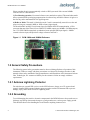
4.5 Verifying Firmware Update
Power cycle the unit with the pin 16 of J1 (ISP#) left floating. The Red LED should light up
momentarily.
During power on, the unit sends an ID string out of the serial port at 115200 Baud by default. The
firmware version can also be queried by sending the *IDN? command. Verify that the firmware
version is the version that was downloaded.
© 2014 Jackson Labs Technologies, Inc.
35
RCM Reference User Manual
36
© 2014 Jackson Labs Technologies, Inc.
RCM Reference User Manual
GPSCon Utility
5.1 Description
GPSCon is a program for the monitoring and control of a variety of GPS time and frequency standard
receivers. It communicates with the receiver using the SCPI command set. This utility can be
obtained directly from Real Ham Radio.com at the following URL:
http://www.realhamradio.com/gpscon-buy-now.htm
GPSCon can be used to monitor the RCM Reference, even though the board does not contain an
internal GPS receiver.
Important note: On newer, faster computers running Windows 7, GPSCon may not acquire data
correctly. If you encounter this problem, it is recommended that you install GPSCon on a slower
computer using Windows XP.
5.2 Installation
Follow the directions that come with GPSCon for installing the utility on your computer.
5.3 Using GPSCon
The GPSCon utility has a help file that should be consulted in order to get the full functionality of
this utility. Only a few of the features and commands are mentioned in this appendix for convenience.
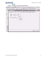
5.3.1 Setting the options
To set up the options for your GPSCon session, press the “Options” button below the display area.
The window shown in Figure 5.1 will appear. You can select from the tabs which options you wish to
set.
© 2014 Jackson Labs Technologies, Inc.
37
RCM Reference User Manual
Figure 5.1
Options window
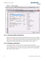
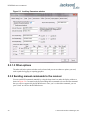
5.3.1.1 Communication Parameters
Before you can use GPSCon you must set the communication parameters for your system. Open the
dialog box by pressing the “Options” button. Then select the “Coms” tab. You will see the window
shown in Figure 5.2. Select the correct COM port for your computer and set the baud rate to 115200,
parity to None, Data Bits to 8 and Stop Bits to 1. Set Flow Control to “None”. Once you have
configured the communication parameters, press the “OK” button to close the window.
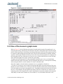
5.3.1.2 Auxiliary parameters
After pressing the “Options” button, you can select “Auxiliary” and set other options or
measurements. See Figure 5.3 for an example of an auxiliary measurement. You will notice that the
“Aux 1 request string” has been set to meas:current?<CD> and the “Log Aux1” box is checked.
In the area below labeled “Traces to be visible on the graph”, the box “Aux 1” is checked and the
label “OCXO curr” has been added.
38
© 2014 Jackson Labs Technologies, Inc.
RCM Reference User Manual
Figure 5.2
Setting the communications parameters
© 2014 Jackson Labs Technologies, Inc.
39
RCM Reference User Manual
Figure 5.3
Auxiliary Parameters window
5.3.1.3 Other options
The other tabs in the options window can be selected and you can set whatever options you need,
such as paths for logging or exporting graphics.
5.3.2 Sending manual commands to the receiver
You can send SCPI commands manually by using the drop-down box under the display window as
shown in Figure 5.4. Care must be taken when sending these commands so be sure that the command
that you select is supported by the RCM Reference. Once you’ve selected the command, you can
press “Send” to send it to the RCM Reference.
40
© 2014 Jackson Labs Technologies, Inc.
RCM Reference User Manual
Figure 5.4
Sending manual commands
5.3.3 Use of the mouse in graph mode
Refer to Figure 5.5 for the following description. In graph mode the span of the graph may be set
using the span setting. Alternatively, the start and or stop time of the graph may be locked using the
mouse. Set the start time by left clicking on the desired start point. If you wish, the stop time may also
be locked by right clicking the desired stop point. This can all be unlocked by left double-clicking
anywhere on the graph. Double-click always causes all of the selected span data to be displayed. At
the next update cycle, the selected span, if not set to zero, will be enforced. However, the left click,
and if chosen the right click, always overrides the span setting.
To display all of the data in the file without manually setting the span to zero, you should right
double-click in the graph. This has the effect of setting the start time to zero, the stop time to infinity,
and asserting the mouse override condition. To release, left double-click.
Since this is harder to describe than to actually do, here is a paraphrase of the above:
"To zoom in: The mouse is used to set the left extent and the right extent of the portion of the curve
that the user wants to fill the screen. Click once with the left mouse button on the point that marks the
left side of what you want to be the magnified curve. Immediately that point becomes the left end of
the curve. Then similarly click the right mouse button on the curve at the time you wish to be the
right most portion of the magnified curve and it immediately becomes the end point on the right side.
And, finally to return to the zoomed out ("fit to window") view, left double-click on the curve."
© 2014 Jackson Labs Technologies, Inc.
41
RCM Reference User Manual
Remember, in order to see all the data in the log file, you must either set the span control to zero, or
right double-click in the graph.
When you have locked the start and stop time using the mouse, you can scroll left or right through the
data without changing the span. To scroll to a later time, use Shift + Left click. To scroll to an earlier
time, use Shift + Right click. Double left click to release everything.
The time span indication at the lower right of the graph will turn red to signify that mouse override is
in effect.
Figure 5.5
42
Graph display
© 2014 Jackson Labs Technologies, Inc.
RCM Reference User Manual
Figure 5.6
Expanded Graph Display
5.3.4 Exporting the graphics
The settings which control the mode of the Export function are contained in the Options dialog.
Export allows you to create an image file of either the graph or the satellite map. You select which
you want using the radio buttons. If you select 'Graph', you have the option to export only that which
is currently visible, or to export the graph which is a plot of the entire logfile contents. Use the
checkbox "All" to make this choice.
You may nominate a size in X and Y. The file format may be .BMP, .JPG, .GIF, or .PNG. Your settings
will be stored and will be the default next time you open this dialog.
If you choose to export the graph, you might want to override the TI max setting in force on the
screen display. You may do this by entering a non-zero value into the 'Override TI' control. A value
of zero causes the export to take the same setting if any as the screen display.
The export may be done automatically on a timed basis. Simply enter a non-zero value in seconds to
choose an export time interval. To manually export in accordance with the settings, press the 'Export'
button.
© 2014 Jackson Labs Technologies, Inc.
43
RCM Reference User Manual
5.4 Interpreting the Data
Figure 5.5 shows the data acquired by the RCM Reference unit over a period of more than 200 hours
The red trace is EFC (crystal frequency control voltage). The crystal is aging (becoming faster in
frequency over time). This requires the control voltage to be lowered to maintain 10.0MHz exactly.
A drift of ~2mV is visible over 200 hours. On the left side of the screen the EFC range over this 200
hour plot is displayed vertically as 0.00193V. This means the drift of the EFC voltage due to aging is
~88mV per year. The EFC sensitivity of the crystal is about 8Hz per volt, so the crystal ages at:
8Hz/V * 0.088V/Year = 0.704Hz/Year drift.
At 10MHz:
0.704Hz / 10MHz = 7.04E-08 aging rate per year.
This is the same as 0.2ppb drift due to aging per day.This crystal aging is fully compensated by the
firmware with and without GPS reception of course.
In Figure 5.6, which is a zoom of Figure 5.5, we can see the phase offset error of the internal OCXO
to the external 1PPS reference. We can see the maximum drift is -77ns to +93ns. The average is (TI
av=-0.03ns). The standard deviation over the 200 hour plot is sd=11ns. This means the average error
of the 10MHz phase of this unit over 200 hours is only +/-11ns rms. Or, in other words the average
jitter (wander) over 200 hours of operation is:
11ns / 200Hrs = 1.528E-014
or in other words the unit performs as well as a high quality Cesium Atomic reference clock over
long periods of time. The unit disciplines its internal 10MHz reference to within less than +/-80ns
peak to peak of the external 1PPS reference at all times, which is less than one complete clock cycle
at 10MHz.
44
© 2014 Jackson Labs Technologies, Inc.
RCM Reference User Manual
Certification and
Warranty
6.1 Certification
Jackson Labs Technologies, Inc. certifies that this product met its published specifications at time of
shipment.
6.1.1 Warranty
This Jackson Labs Technologies, Inc. hardware product is warranted against defects in material and
workmanship for a period of 1 (one) year from date of delivery. During the warranty period Jackson
Labs Technologies, Inc. will, at its discretion, either repair or replace products that prove to be
defective. Jackson Labs Technologies, Inc. does not warrant that the operation for the software,
firmware, or hardware shall be uninterrupted or error free even if the product is operated within its
specifications.
For warranty service, this product must be returned to Jackson Labs Technologies, Inc. or a service
facility designated by Jackson Labs Technologies, Inc. Customer shall prepay shipping charges (and
shall pay all duties and taxes) for products returned to Jackson Labs Technologies, Inc. for warranty
service. Except for products returned to Customer from another country, Jackson Labs Technologies,
Inc. shall pay for return of products to Customer. If Jackson Labs Technologies, Inc. is unable, within
a reasonable time, to repair or replace any product to condition as warranted, the Customer shall be
entitled to a refund of the purchase price upon return of the product to Jackson Labs Technologies,
Inc.
6.1.2 Limitation of Warranty
The foregoing warranty shall not apply to defects resulting from improper or inadequate maintenance
by the Customer, Customer-supplied software or interfacing, unauthorized modification or misuse,
opening of the instruments enclosure or removal of the instruments panels, operation outside of the
environmental or electrical specifications for the product, or improper site preparation and
maintenance. JACKSON LABS TECHNOLOGIES, INC. SPECIFICALLY DISCLAIMS THE
IMPLIED WARRANTIES OF MERCHANTABILITY AND FITNESS FOR A PARTICULAR
© 2014 Jackson Labs Technologies, Inc.
45
RCM Reference User Manual
PURPOSE. No license, express or implied, by estoppel or otherwise, to any intellectual
property rights is granted by this document. Jackson Labs Technologies, Inc. products are not
intended for use in medical, life saving, or life sustaining applications.
6.1.3 Exclusive Remedies
THE REMEDIES PROVIDED HEREIN ARE THE CUSTOMER'S SOLE AND EXCLUSIVE
REMEDIES. JACKSON LABS TECHNOLOGIES, INC. SHALL NOT BE LIABLE FOR
ANY DIRECT, INDIRECT, SPECIAL, INCIDENTAL, OR CONSEQUENTIAL DAMAGES,
WHETHER BASED ON CONTRACT, TORT, OR ANY OTHER LEGAL THEORY.
46
© 2014 Jackson Labs Technologies, Inc.