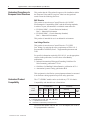
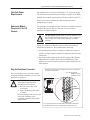
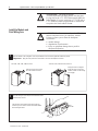
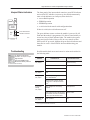
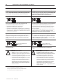
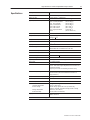
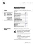
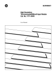
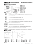
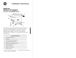
1
Looking for more information? Visit us on the web at http://www.artisan-scientific.com for more information: • Price Quotations • Drivers· Technical Specifications. Manuals and Documentation Artisan Scientific is You~ Source for: Quality New and Certified-Used/Pre:-awned ECJuiflment • Fast Shipping and DelIve1y • Tens of Thousands of In-Stock Items • Equipment Demos • Hundreds of Manufacturers Supported • Leasing / Monthly Rentals Service Center Repairs Experienced Engineers and Technicians on staff in our State-of-the-art Full-Service In-House Service Center Facility • Consignment InstraView Remote Inspection Remotely inspect equipment before purchasing with our Innovative InstraView-website at http://www.instraview.com We bUy used equipment! We also offer credit for Buy-Backs and Trade-Ins Sell your excess. underutilized. and idle used equipment. Contact one of our Customer Service Representatives todayl Talk to a live person: 88EM38-S0URCE fB88-887-68721 I Contact us by email: [email protected] I Visit our website: http://www.artisan-scientific.com Installation Instructions (Catalog Number 1771-IXHR Series C) Contents This icon is used when additional information is available in the High Resolution Thermocouple/Millivolt Input Module User Manual, publication 1771-6.5.131. Use this document as a guide when installing the 1771-IXHR/C High Resolution Thermocouple/mV input module. To Prevent Electrostatic Discharge Understand Compliance to European Union Directives Understand Product Compatibility Calculate Power Requirements Determine Module Placement See page Below 2 2 3 3 Key the Backplane Connector 3 Install the Module and Field Wiring Arm 4 Connect Wiring to the Field Wiring Arm 5 Ground the Chassis and Module 6 Configure the Module 7 For this reference information Status Indicators Troubleshooting Specifications Prevent Electrostatic Discharge See page 9 9 11 The High Resolution Thermocouple/Millivolt input module is sensitive to electrostatic discharge. ! ATTENTION: Electrostatic discharge can damage integrated circuits or semiconductors if you touch backplane connector pins. Follow these guidelines when you handle the module: • Touch a grounded object to discharge static potential • Wear an approved wrist-strap grounding device • Do not touch the backplane connector or connector pins • Do not touch circuit components inside the module • If available, use a static-safe work station • When not in use, keep the module in its static-shield bag Publication 1771-5.66 – October 1998 2 High Resolution Thermocouple/Millivolt Input Module Understand Compliance to European Union Directives This product has the CE mark and is approved for installation within the European Union and EEA regions. It has been designed and tested to meet the following directives. EMC Directive This product is tested to meet Council Directive 89/336/EEC Electromagnetic Compatibility (EMC) and the following standards, in whole or in part, documented in a technical construction file: • EN 50081-2EMC – Generic Emission Standard, Part 2 – Industrial Environment • EN 50082-2EMC – Generic Immunity Standard, Part 2 – Industrial Environment This product is intended for use in an industrial environment. Low Voltage Directive This product is tested to meet Council Directive 73/23/EEC Low Voltage, by applying the safety requirements of EN 61131–2 Programmable Controllers, Part 2 – Equipment Requirements and Tests. For specific information required by EN 61131-2, see the appropriate sections in this publication, as well as these Allen-Bradley publications: • Industrial Automation Wiring and Grounding Guidelines For Noise Immunity, publication 1770-4.1 • Guidelines for Handling Lithium Batteries, publication AG-5.4 • Automation Systems Catalog, publication B111 This equipment is classified as open equipment and must be mounted in an enclosure during operation to provide safety protection. Understand Product Compatibility The 1771-IXHR/C module can be used with any 1771 I/O chassis. Compatibility and data table use is listed below. Use of Data Table atalo Catalog Nu ber Number 1771-IXHR/C Compatibility Input Image a e Bits Output Image a e Bits Read Block Bloc Words Write Block Bloc Words 1/2-Slot 1-Slot 2-Slot a i Chassis Series erie 8 8 12/13 27/28 Yes Yes Yes A, B Addressing A = Compatible with 1771-A1, -A2, -A4 chassis B = Compatible with 1771-A1B, -A2B, -A3B, -A4B chassis Yes = Compatible without restriction No = Restricted to complementary module placement Do not use this module with Cat. No. 1771-AL adapter, PLC-2/20 or 2/30 programmable controllers. Publication 1771-5.66 – October 1998 High Resolution Thermocouple/Millivolt Input Module Calculate Power Requirements 3 The module receives its power through the 1771 I/O power supply. The maximum current drawn by the module is 850mA (4.25 Watts). Add this current to the requirements of all other modules in the I/O chassis to prevent overloading the chassis backplane and/or backplane power supply. Determine Module Placement in the I/O Chassis You can place your module in any I/O module slot of the I/O chassis except for the extreme left slot. This slot is reserved for PC processors or adapter modules. ! ATTENTION: Do not insert or remove modules from the I/O chassis while system power is ON. Failure to observe this rule could result in damage to module circuitry. Group your modules to minimize adverse affects from radiated electrical noise and heat. We recommend the following. • Group analog input and low voltage dc modules away from ac modules or high voltage dc modules to minimize electrical noise interference. • Do not place this module in the same I/O group with a discrete high-density I/O module when using 2-slot addressing. This module uses a byte in both the input and output image tables for block transfer. Key the Backplane Connector Place your module in any slot in the chassis except the leftmost slot which is reserved for processors or adapters. ! Position the keying bands in the backplane connectors to correspond to the key slots on the module. Place the keying bands: between 20 and 22 between 24 and 26 ATTENTION: Observe the following precautions when inserting or removing keys: • insert or remove keys with your fingers • make sure that key placement is correct Upper Connector I/O chassis Incorrect keying or the use of a tool can result in damage to the backplane connector and possible system faults. 11022-I You can change the position of these bands if subsequent system design and rewiring makes insertion of a different type of module necessary. Publication 1771-5.66 – October 1998 4 High Resolution Thermocouple/Millivolt Input Module ! Install the Module and Field Wiring Arm ! ATTENTION: The High Resolution Thermocouple/Millivolt Input Module uses the same keying slots as the 1771–IXE Thermocouple/Millivolt Input Module. If you are replacing a 1771–IXE with a 1771–IXHR, the ladder program must be modified to accept the new block transfer format. ATTENTION: Remove power from the 1771 I/O chassis backplane before you install the module. Failure to remove power from the backplane could cause: • module damage • degradation of performance • injury or equipment damage due to possible unexpected operation 1 Place the module in the card guides on the top and bottom of the chassis that guide the module into position. Important: Apply firm even pressure on the module to seat it into its backplane connector. 1771-A1B, -A2B, -A3B, -A4B I/O chassis Snap the chassis latch over the top of the module to secure it. 2 1771-A1B, -A2B, -A4B Series B I/O chassis Swing the chassis locking bar down into place to secure the modules. Make sure the locking pins engage. Attach the wiring arm (1771-WI) to the horizontal bar at the bottom of the I/O chassis. The wiring arm pivots upward and connects with the module so you can install or remove the module without disconnecting the wires. Publication 1771-5.66 – October 1998 1771-WI High Resolution Thermocouple/Millivolt Input Module Connect Wiring to the Field Wiring Arm 5 Connect your I/O devices to the field wiring arm (cat. no. 1771-WI) shipped with the module. ATTENTION: Remove power from the 1771 I/O chassis backplane and field wiring arm before removing or installing an I/O module. ! • Failure to remove power from the backplane or wiring arm could cause module damage, degradation of performance, or injury. • Failure to remove power from the backplane could cause injury or equipment damage due to possible unexpected operation. Connection Diagram for the High Resolution Thermocouple/mV Input Module (cat. no. 1771-IXHR/D) Terminal Identification + Functional Ground Channel 1 – + Channel 2 – Functional Ground 1 3 4 5 6 7 8 1 2 Input 1 (+ lead) Input 1 (– lead) Input 2 (+ lead) Input 2 (– lead) Input 3 (+ lead) Input 3 (– lead) Input 4 (+ lead) Input 4 (– lead) Not Used Not used Input 5 (+ lead) Input 5 (– lead) Input 6 (+ lead) Input 6 (– lead) Input 7 (+ lead) Input 7 (– lead) Input 8 (+ lead) Input 8 (– lead) 9 10 11 12 18 17 16 15 14 13 12 11 10 9 8 7 6 5 4 3 2 1 Function 13 14 15 16 17 18 Terminal Do not use 9 and 10 – reserved for cold junction compensation within wiring arm. Short circuit unused pins Connect positive thermocouple leads to even–numbered terminals, negative leads to odd–numbered terminals. Ground cable shield to I/O chassis mounting bolt. Field Wiring Arm Cat. No. 1771–WI Short circuit all unused channels by connecting a jumper wire from the + terminal to the – terminal The sensor cable must be shielded. The shield must: • extend the length of the cable, but be connected only at the 1771 I/O chassis • extend up to the point of termination Important: The shield should extend to the termination point, exposing just enough cable to adequately terminate the inner conductors. Use heat shrink or another suitable insulation where the wire exits the cable jacket. 10527–I Publication 1771-5.66 – October 1998 6 High Resolution Thermocouple/Millivolt Input Module Ground the Chassis and Module Use the following diagrams to ground your I/O chassis and input module. Follow these steps to prepare the cable: 1 Chassis Ground When you connect grounding conductors to the I/O chassis grounding stud, place a star washer under the first lug, then place a nut with captive lock washer on top of each ground lug. Remove a length of cable jacket from the Belden 8761 cable (mV) or shielded thermocouple wire. Ground Lug Nut Nut and Captive Washer Belden 8761 Cable 2 Pull the foil shield and bare drain wire from the insulated wires. Grounding Stud Bare drain wire Star Washer I/O Chassis Side Plate Insulated wires Ground Lug1 Shield and Drain twisted together 1Use the cup washer if crimp-on lugs are not used. Foil shield Single-point Grounding 3 Twist the foil shield and drain wire together to form a single strand. 4 Attach a ground lug. Extend shield to termination point. Expose just enough cable to adequately terminate inner conductors. Use heat shrink tubing or other suitable insulation where wire exits cable jacket. When using shielded cable wire, ground the foil shield and drain wire only at one end of the cable. We recommend that you wrap the foil shield and drain wire together and connect them to a chassis mounting bolt. At the opposite end of the cable, tape exposed shield and drain wire with electrical tape to insulate it from electrical contact. Refer to Wiring and Grounding Guidelines, publication 1770-4.1 for additional information. Publication 1771-5.66 – October 1998 Shield and Drain twisted together #10 Thread-forming screw External-tooth Washers High Resolution Thermocouple/Millivolt Input Module Configure the Module Dec. Bits 15 Octal Bits 17 Word 1 0.1s 0 0.5s 0 0.6s 0 0.7s 0 14 16 0 0 0 0 Use the configuration information below to configure your module to your specifications.For detailed configuration information, see chapter 5 of your High Resolution Thermocouple/mV Input Module User Manual (publication 1771-6.5.131). 13 12 11 10 09 15 14 13 12 11 Sample time 0 0 1 0 0 0 0 1 0 1 0 1 1 0 0 1 1 1 0 0 0.8s 0 1 0 0 0 0 0.9s 0 1 0 0 1 0 0 0 1.0s 0 0 1 0 0 0 1.5s 2.0s 2.5s 3.0s 0 1 1 1 0 1 1 1 0 1 0 1 0 0 0 0 0 1 1 0 0 0 1 1 0 0 0 1 1 Real time sample interval bits - determine the sample time for updating module inputs. You select sample time in 0.025 second intervals using binary code. (All values between 0.025 and 3.1 seconds in 0.025 second intervals are available.) Important: Use decimally addressed bit locations for PLC-5 processors. Temperature scale bit (T) - when set (1), reports temperature in oF; when reset (0), in oC. The module ignores this bit for millivolt inputs. 2 3 4, 6, 8, 10, 12, 14, 16, 18 5, 7, 9, 11, 13, 15, 17, 19 20, 21, 22, 23, 24, 25, 26, 27 28 7 08 10 T 07 07 Z 06 06 E 05 05 03 03 02 02 0 1 04 04 Type 0 1 00 00 0 1 01 01 Type 0 1 0 1 1 0 0 0 0 1 1 0 Millivolt input “B” thermocouple “E” thermocouple “J” thermocouple 0 0 0 1 0 1 1 0 1 1 “K” thermocouple 0 1 De Description o “R” thermocouple 1 1 0 1 “S” thermocouple 1 0 1 1 0 “T” thermocouple 0 0 1 0 1 0 (Bits 00-02) Input type codes for inputs 1 thru 8 (or 1 thru 4 if bit 06 is set to 1) - tells the module what type of input device you connected to the module. See table above. (Bits 03-05) Input type codes for inputs 5 thru 8 (bit 06 must be set to 1) - tells the module what type of input device you connected to inputs 5 thru 8. See table above. 1 0 1 Enable bit for input types (E) - When set to 0 bits 00–02 define input type for all channels. When set to 1 bits 00–02 defines input type for channels 1–4, and bit 03–05 defines input type for channels 5–8. Zoom enable (Z) - Enables X10 magnification when millivolt inputs have been selected. Enabling this feature causes the BTR data to display +30.000mV around the value selected by word 2. Use the digital filter (word 3) to stabilize the readings when using this mode. 0 = normal 10mV; 1 = X10 (1mV) Zoom value for group 2 (channels 5-8) Zoom value for group 1 (channels 1-4) Zoom center value for channels 1–8. These values are used when millivolt inputs have been selected and bit 07 of word 1 has been set to enable zoom (i.e. 1µV display resolution). Enter a value in 2’s complement binary format ranging from –70mV to +70mV. The displayed range will then be +30.000mV around the selected value, displayed in 1µV increments. Filter value for group 2 (channels 5-8) Filter value for group 1 (channels 1-4) Filter values for channels 1–8. The filter operates on the display data only. Alarms, underrange and overrange operate in real time. The filter constant is equal to: TC = 0.025(1 + filter value). Zoom values Filter values Low Alarm Values for channels 1-8 Low channel alarm values High Alarm Values for channels 1-8 High channel alarm values Low and High channel alarm values that you enter via the terminal in 2’s complementary binary. Store low and high channel alarms in pairs, low alarm values in even–numbered words, high alarm values in odd–numbered words. For example, store channel 1 low and high alarm values in words 4 and 5, respectively. Alarms are disabled by setting the low alarm equal to the high alarm. If the zoom feature is enabled, the alarm values should be the difference between the ”actual alarm limit” and ”zoom center value” in word 2. Calibration words are a composite of two independent bytes for each channel. Enter calibration data in signed magnitude binary only. The most significant bit in each byte is the sign bit; set for negative, reset for positive. Use the high byte (bits 08–15) for offset correction, the low byte (bits 00–07) for gain correction for each channel. Auto-calibration Request Word - Used to automatically calibrate selected channels and save the calibration constants in EEPROM. Channel 1-8 calibration values Auto-calibration Request Word Publication 1771-5.66 – October 1998 8 High Resolution Thermocouple/Millivolt Input Module Use the following table to read data from your input module. Dec. Bits 15 14 13 12 11 10 09 08 07 06 05 04 03 02 01 00 Octal Bits 17 16 15 14 13 12 11 10 07 06 05 04 03 02 01 00 EE DCB HCJ LCJ RTS OR PU Word 1 Not used Dynamic clamp bit - (DCB) Prevents rapid changes in data due to data corruption over the opto–isolation barrier as a result of ESD, radiation bursts, etc. 0 = feature active 1 = feature inhibited High cold junction temperature bit - (HCJ) set when the cold junction temperature exceeds 60.0oC or 140.0oF. Real time sample fault bit – (RTS) set when the module updates an input buffer with new data before the processor has read the previous data. Monitor this bit only if you select real time sampling. Low cold junction temperature bit - (LCJ) set when the cold junction temperature is less than 0.0oC or 32.0oF. 2 17 16 15 14 13 12 11 10 07 06 Inputs overrange 05 04 03 02 01 00 Inputs underrange Inputs > high alarms Description Inputs overrange and underrange for c annel 1-8 channels Underrange bit for each channel is set to indicate an input is out of range: bit 00 for channel 1 thru bit 07 for channel 8. Overrange bit for each channel is set to indicate an input is out of range: bit 08 for channel 1 thru bit 15 for channel 8. Also set for open channel detection. 3 Diagnostics Power up bit – (PU) set to indicate that the module is waiting for its first write block transfer. Out of range bit – (OR) set if one or more channel inputs are above or below the range for which you configured the module. EEPROM status bit – (EE) calibration values could not be read. Octal Bits De Description o Inputs < low alarms Low alarm bit for each channel is set to indicate the input is less than the low limit value you entered in the corresponding low alarm word (BTW word 4, 6, 8, 10, 12, 14, 16, or 18): bit 00 for channel 1 thru bit 07 for channel 8. High alarm bit for each channel is set to indicate the input has exceeded the high limit value you entered in the corresponding high alarm word (BTW word 5, 7, 9, 11, 13, 15, 17, or 19): bit 08 for channel 1 thru bit 15 for channel 8. High and low alarms for c annel 1-8 channels 4, 5, 6, 7, 8, 9, 10, 11 Input for channels 1-8 respectively in 0.1oC or 0.1oF resolution for temperature and 10µV or 1µV resolution for millivolts. Input for channels 1-8 12 Cold junction temperature is provided in 0.1oC or 0.1oF resolution. The filter time constant (Tau) for this value is fixed at 6.4 seconds. Cold Junction Temperature in _C or _F 13 Uncalibrated channel bits CF Calibration fault bit EE Not used EEPROM fault bit S G O Auto-calibration word Offset calibration complete bit Gain calibration complete bit Save to EEPROM bit Default Configuration If a write block of five words with all zeroes is sent to the module, default selections will be: • millivolt input • zoom center = 0mV • temperature reported in degrees Celsius • real time sampling (RTS) inhibited • no filtering • no auto-calibration Publication 1771-5.66 – October 1998 High Resolution Thermocouple/Millivolt Input Module Interpret Status Indicators 9 The front panel of the input module contains a green RUN indicator and a red FAULT indicator. At power-up, the module momentarily turns on both indicators as a lamp test, then checks for: • correct RAM operation • EPROM operation • EEPROM operation • a valid write block transfer with configuration data TC/MV Module If there is no fault, the red indicator turns off. RUN FLT Green RUN indicator The green indicator comes on when the module is powered. It will flash until the module is programmed. If a fault is found initially or occurs later, the red fault indicator lights. The module also reports status and specific faults (if they occur) in every transfer of data (BTR) to the PC processor. Monitor the green and red indicators and status bits in word 1 of the BTR file when troubleshooting your module. Red FAULT indicator 10528-I Troubleshooting For detailed troubleshooting information, see chapter 7 of your High Resolution Thermocouple/Millivolt Input Module User Manual (publication 1771-6.5.131). Possible module fault causes and corrective action are described in the following table. Indicators RUN (green) off FLT (red) off Probable Cause Recommended Action No power to module Check power to I/O chassis. Cycle as necessary. Possible short on module Replace module. LED driver failure RUN (green) on FLT (red) on Microprocessor, oscillator or EPROM failure RUN (green) off FLT (red) on If immediately after power–up, indicates RAM or EPROM failure.1 If during operation, indicates possible microprocessor or backplane interface failure.1 RUN (green) blinking, FLT (red) off Power–up diagnostics successfully completed. Normal operation. If LED continues to flash, and write block Replace module. transfers (BTW) cannot be accomplished, you have a possible interface failure. RUN (green) on FLT (red) off 1 Normal operation None When red LED is on, the watchdog timer has timed out and backplane communications are terminated. Your user program should monitor communication. Publication 1771-5.66 – October 1998 10 High Resolution Thermocouple/Millivolt Input Module CSA Hazardous Location Approval Approbation d’utilisation dans des emplacements dangereux par la CSA CSA certifies products for general use as well as for use in hazardous locations. Actual CSA certification is indicated by the product label as shown below, and not by statements in any user documentation. La CSA certifie les produits d’utilisation générale aussi bien que ceux qui s’utilisent dans des emplacements dangereux. La certification CSA en vigueur est indiquée par l’étiquette du produit et non par des affirmations dans la documentation à l’usage des utilisateurs. Example of the CSA certification product label Exemple d’étiquette de certification d’un produit par la CSA To comply with CSA certification for use in hazardous locations, the following information becomes a part of the product literature for CSA-certified Allen-Bradley industrial control products. Pour satisfaire à la certification de la CSA dans des endroits dangereux, les informations suivantes font partie intégrante de la documentation des produits industriels de contrôle Allen-Bradley certifiés par la CSA. • This equipment is suitable for use in Class I, Division 2, Groups A, B, C, D, or non-hazardous locations only. • The products having the appropriate CSA markings (that is, Class I Division 2, Groups A, B, C, D), are certified for use in other equipment where the suitability of combination (that is, application or use) is determined by the CSA or the local inspection office having jurisdiction. • Cet équipement convient à l’utilisation dans des emplacements de Classe 1, Division 2, Groupes A, B, C, D, ou ne convient qu’à l’utilisation dans des endroits non dangereux. • Les produits portant le marquage approprié de la CSA (c’est à dire, Classe 1, Division 2, Groupes A, B, C, D) sont certifiés à l’utilisation pour d’autres équipements où la convenance de combinaison (application ou utilisation) est déterminée par la CSA ou le bureau local d’inspection qualifié. Important: Due to the modular nature of a PLC control system, the product with the highest temperature rating determines the overall temperature code rating of a PLC control system in a Class I, Division 2 location. The temperature code rating is marked on the product label as shown. Temperature code rating Important: Par suite de la nature modulaire du système de contrôle PLC, le produit ayant le taux le plus élevé de température détermine le taux d’ensemble du code de température du système de contrôle d’un PLC dans un emplacement de Classe 1, Division 2. Le taux du code de température est indiqué sur l’étiquette du produit. Taux du code de température Look for temperature code rating here The following warnings apply to products having CSA certification for use in hazardous locations. Le taux du code de température est indiqué ici Les avertissements suivants s’appliquent aux produits ayant la certification CSA pour leur utilisation dans des emplacements dangereux. ATTENTION: Explosion hazard — ! • Substitution of components may impair suitability for Class I, Division 2. • Do not replace components unless power has been switched off or the area is known to be non-hazardous. • Do not disconnect equipment unless power has been switched off or the area is known to be non-hazardous. • Do not disconnect connectors unless power has been switched off or the area is known to be non-hazardous. Secure any user-supplied connectors that mate to external circuits on an Allen-Bradley product using screws, sliding latches, threaded connectors, or other means such that any connection can withstand a 15 Newton (3.4 lb.) separating force applied for a minimum of one minute. Le sigle CSA est la marque déposée de l’Association des Standards pour le Canada. PLC est une marque déposée de Allen-Bradley Company, Inc. CSA logo is a registered trademark of the Canadian Standards Association PLC is a registered trademark of Allen-Bradley Company, Inc. Publication 1771-5.66 – October 1998 AVERTISSEMENT: Risque d’explosion — ! • La substitution de composants peut rendre ce matériel inacceptable pour lesemplacements de Classe I, Division 2. • Couper le courant ou s’assurer quel’emplacement est désigné non dangereux avant de remplacer lescomposants. • Avant de débrancher l’équipement, couper le courant ou s’assurer que l’emplacement est désigné non dangereux. • Avant de débrancher les connecteurs, couper le courant ou s’assurer que l’emplacement est reconnu non dangereux. Attacher tous connecteurs fournis par l’utilisateur et reliés aux circuits externes d’un appareil Allen-Bradley à l ’aide de vis, loquets coulissants, connecteurs filetés ou autres moyens permettant aux connexions de résister à une force de séparation de 15 newtons (3,4 lb. - 1,5 kg) appliquée pendant au moins une minute. High Resolution Thermocouple/Millivolt Input Module Specifications Description Value Number of Inputs 8, all of the same type or 4 each of 2 different types Module Location 1771 I/O chassis – 1 module slot Type of Input (Selectable) Type B, Pt–30% Rh/Pt–6% Rh Type E, chromel/constantan Type J, iron/constantan Type K, chromel/alumel Type R, Pt/Pt–13% Rh Type S, Pt/Pt–10% Rh Type T, copper/constantan Millivolt Thermocouple Linearization IPTS–68 standard, NBS MN–125 Cold Junction Compensation Range: 0 to 60oC Accuracy: +0.5oC Temperature Scale (Selectable) oC or oF Input Resolution 3.2328µV Display Resolution 0.1oC, 0.1oF; or 1.0µV, 10µV Isolation Voltage This isolation meets or exceeds the requirements of UL Standard 508, and CSA Standard C22.2 No. 142. Common Mode Rejection 120dB at 60Hz, up to 1000V peak Common Mode Impedance Greater than 10 megohms Normal Mode Rejection 60dB at 60Hz over +100mV Input Overvoltage Protection 120V rms, continuous Open Input Detection Open input produces an overrange in less than 10 seconds Data Format 2’s complement binary Calibration Methods Auto – Auto-calibration for offset and gain Manual – Zero offset and gain adjustment for each channel via programming terminal Verify every six months for maintaining absolute accuracy Processor Compatibility PLC-3 or PLC-5 family processor using the 1771 I/O structure and block transfer. (Not recommended for use with PLC-2 family processors.) Backplane Power Consumption 850mA @ 5V Power Dissipation 4.25 Watts maximum Thermal Dissipation 14.5 BTU/hr Environmental Conditions Operating Temperature: Rate of Change: Storage Temperature: Relative Humidity: Keying 11 (320 to 1800oC) (–270 to 1000oC) (–210 to 1200oC) (–270 to 1380oC) (–50 to 1770oC) (–50 to 1770oC) (–270 to 400oC) (–100 to +100mV dc) 0 to 60oC (32 to 140oF) Ambient changes greater than 0.5oC per minute may temporarily degrade performance during periods of change –40 to 85oC (–40 to 185oF) 5 to 95% (without condensation) Between 20 and 22 Between 24 and 26 Specifications continued on next page Publication 1771-5.66 – October 1998 12 High Resolution Thermocouple/Millivolt Input Module Description Value Conductors Wiring Category Use Belden 8761 shielded twisted pair for mV Use thermocouple manufacturer recommended shielded thermocouple wire for all thermocouple inputs. 2 Field Wiring Arm Cat. No. 1771-WI Wiring Arm Screw Torque 7-9 inch-pounds Agency Certification (when product is marked) • • • • User Manual Publication 1771-6.5.80 CSA certified CSA Class I, Division 2, Groups A, B, C, D certified UL listed CE marked for all applicable directives Refer to publication 1770-4.1, Industrial Automation Wiring and Grounding Guidelines for Noise Immunity. Differences Between Series A, Series B and Series C Modules The Series B and C versions of the High Resolution Thermocouple/Millivolt module have CE certification. In all other respects, the modules are equal. Allen-Bradley, a Rockwell Automation Business, has been helping its customers improve productivity and quality for more than 90 years. We design, manufacture and support a broad range of automation products worldwide. They include logic processors, power and motion control devices, operator interfaces, sensors and a variety of software. Rockwell is one of the world’s leading technology companies. Worldwide representation. Argentina • Australia • Austria • Bahrain • Belgium • Brazil • Bulgaria • Canada • Chile • China, PRC • Colombia • Costa Rica • Croatia • Cyprus • Czech Republic • Denmark • Ecuador • Egypt • El Salvador • Finland • France • Germany • Greece • Guatemala • Honduras • Hong Kong • Hungary • Iceland • India • Indonesia • Ireland • Israel • Italy • Jamaica • Japan • Jordan • Korea • Kuwait • Lebanon • Malaysia • Mexico • Netherlands • New Zealand • Norway • Pakistan • Peru • Philippines • Poland • Portugal • Puerto Rico • Qatar • Romania • Russia–CIS • Saudi Arabia • Singapore • Slovakia • Slovenia • South Africa, Republic • Spain • Sweden • Switzerland • Taiwan • Thailand • Turkey • United Arab Emirates • United Kingdom • United States • Uruguay • Venezuela • Yugoslavia Allen-Bradley Headquarters, 1201 South Second Street, Milwaukee, WI 53204 USA, Tel: (1) 414 382-2000 Fax: (1) 414 382-4444 Publication 1771-5.66 – October 1998 Publication 1771-5.66 – October 1998 PN 955132–12 Copyright 1998 Rockwell Automation Printed in USA Looking for more information? Visit us on the web at http://www.artisan-scientific.com for more information: • Price Quotations • Drivers· Technical Specifications. Manuals and Documentation Artisan Scientific is You~ Source for: Quality New and Certified-Used/Pre:-awned ECJuiflment • Fast Shipping and DelIve1y • Tens of Thousands of In-Stock Items • Equipment Demos • Hundreds of Manufacturers Supported • Leasing / Monthly Rentals Service Center Repairs Experienced Engineers and Technicians on staff in our State-of-the-art Full-Service In-House Service Center Facility • Consignment InstraView Remote Inspection Remotely inspect equipment before purchasing with our Innovative InstraView-website at http://www.instraview.com We bUy used equipment! We also offer credit for Buy-Backs and Trade-Ins Sell your excess. underutilized. and idle used equipment. Contact one of our Customer Service Representatives todayl Talk to a live person: 88EM38-S0URCE fB88-887-68721 I Contact us by email: [email protected] I Visit our website: http://www.artisan-scientific.com