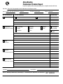
1
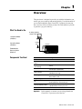
AllenBradley
Classic PLC5
Programmable
Controller
(Cat. No. 1785LT, LT2,
LT3, and LT4)
Quick Start
Important User
Information
Because of the variety of uses for the products described in this
publication, those responsible for the application and use of this
control equipment must satisfy themselves that all necessary steps
have been taken to assure that each application and use meets all
performance and safety requirements, including any applicable laws,
regulations, codes and standards.
The illustrations, charts, sample programs and layout examples
shown in this guide are intended solely for purposes of example.
Since there are many variables and requirements associated with any
particular installation, Allen-Bradley does not assume responsibility
or liability (to include intellectual property liability) for actual use
based upon the examples shown in this publication.
Allen-Bradley publication SGI-1.1, Safety Guidelines for the
Application, Installation, and Maintenance of Solid-State Control
(available from your local Allen-Bradley office), describes some
important differences between solid-state equipment and
electromechanical devices that should be taken into consideration
when applying products such as those described in this publication.
Reproduction of the contents of this copyrighted publication, in
whole or in part, without written permission of Allen-Bradley
Company, Inc., is prohibited.
Throughout this manual we use notes to make you aware of safety
considerations:
!
ATTENTION: Identifies information about practices
or circumstances that can lead to personal injury or
death, property damage or economic loss.
Attention statements help you to:
• identify a hazard
• avoid the hazard
• recognize the consequences
Important:
Identifies information that is critical for successful
application and understanding of the product.
ControlNet is a trademark; PLC is a registered trademark of Allen-Bradley Company, Inc.
Table of Contents
Important User Information . . . . . . . . . . . . . . . . . . . . . . . .
-1
Preface . . . . . . . . . . . . . . . . . . . . . . . . . . . . . . . . . . . . . . .
P-1
Who Should Use This Manual . . . . . . . . . . . . . . . . . . . . . . . . . . .
Purpose of This Manual . . . . . . . . . . . . . . . . . . . . . . . . . . . . . . .
Related Documentation . . . . . . . . . . . . . . . . . . . . . . . . . . . . .
Common Techniques Used in This Manual . . . . . . . . . . . . . . . . . .
AllenBradley Support . . . . . . . . . . . . . . . . . . . . . . . . . . . . . . . .
Local Product Support . . . . . . . . . . . . . . . . . . . . . . . . . . . . . .
Technical Product Assistance . . . . . . . . . . . . . . . . . . . . . . . . .
Your Questions or Comments about This Manual . . . . . . . . . . .
P-1
P-1
P-2
P-3
P-3
P-3
P-3
P-3
Overview . . . . . . . . . . . . . . . . . . . . . . . . . . . . . . . . . . . . . .
1-1
What You Need to Do . . . . . . . . . . . . . . . . . . . . . . . . . . . . . . . . .
Components You Need . . . . . . . . . . . . . . . . . . . . . . . . . . . . . . . .
1-1
1-1
Set up the Hardware . . . . . . . . . . . . . . . . . . . . . . . . . . . . .
2-1
Configure the I/O Chassis . . . . . . . . . . . . . . . . . . . . . . . . . . . .
Install the Hardware . . . . . . . . . . . . . . . . . . . . . . . . . . . . . . . . . .
Ground the I/O Chassis . . . . . . . . . . . . . . . . . . . . . . . . . . . . .
Install the Power Supply . . . . . . . . . . . . . . . . . . . . . . . . . . . . .
Install the PLC5 Processor . . . . . . . . . . . . . . . . . . . . . . . . . . .
Powerup the System . . . . . . . . . . . . . . . . . . . . . . . . . . . . . . .
Install the I/O Modules . . . . . . . . . . . . . . . . . . . . . . . . . . . . . .
Connect the Programming Terminal and the PLC5
Processor to the Communication Card . . . . . . . . . . . . . . . . . .
2-2
2-2
2-3
2-4
2-5
2-5
2-6
Set up the Software . . . . . . . . . . . . . . . . . . . . . . . . . . . . . .
3-1
Install the Software and Set Up the Programming System . . . . . . .
Start the Programming Software . . . . . . . . . . . . . . . . . . . . . . . . .
Powerup the System . . . . . . . . . . . . . . . . . . . . . . . . . . . . . . . . .
3-1
3-1
3-2
Troubleshoot the Processor System . . . . . . . . . . . . . . . . .
4-1
Use the PLC5 Processor Status Indicators . . . . . . . . . . . . . . . . .
4-1
Specifications . . . . . . . . . . . . . . . . . . . . . . . . . . . . . . . . . .
A-1
General . . . . . . . . . . . . . . . . . . . . . . . . . . . . . . . . . . . . . . . . . . .
Processor Specific . . . . . . . . . . . . . . . . . . . . . . . . . . . . . . . . . . .
Battery Specifications . . . . . . . . . . . . . . . . . . . . . . . . . . . . . . . . .
A-1
A-3
A-4
2-6
Preface
Preface
Read this preface to familiarize yourself with the rest of the manual.
This preface covers the following topics:
• who should use this manual
• the purpose of this manual
• how to use this manual
• conventions used in this manual
• Allen-Bradley support
Who Should Use
This Manual
Purpose of This Manual
To use this manual, you should understand programmable controllers
and be able to interpret the ladder logic instructions required to
control your application. For more information, see the documents
listed on the following page or contact your local Allen-Bradley
representative.
This manual is for users of the classic PLC-5R processor. It:
• presents you with the basic information you need to get your
system up and running
• provides “memory jogger” information, such as specific bit and
switch settings for modules
• includes high-level procedures with cross-references to other
manuals for more detail
Publication 178510.3 - October 1996
P–2
Preface
Related Documentation
The following documents contain additional information concerning
the products discussed in this manual.
For more information about:
See this document:
Publication
number:
Classic PLC5 programmable controllers
Classic PLC5 Programmable Controllers User Manual
17856.2.1
To obtain a free copy of this manual, complete and send in the User Manual Request Card
that came packaged with this quick start.
.
Classic PLC5 programmable controllers
Classic PLC5 Programmable Controllers Hardware Installation Manual
17856.6.1
Universal 1771 I/O chassis
Universal I/O Chassis Installation Instructions
17712.10
power supply
Redundant Power Supplies (1771P4R, P6R) Installation Data
17712.166
DH+R network
Enhanced and Ethernet PLC5 Programmable Controllers User Manual
17856.5.12
Data Highway/Data Highway Plus/Data Highway II/Data Highway485
Cable Installation Instructions
17706.2.2
1784KTx Communication Interface Card User Manual
17846.5.22
communication cards
AllenBradley Publication Index (for your specific communication card)
SD499
cables
Classic PLC5 Programmable Controllers User Manual
17856.2.1
batteries
AllenBradley Guidelines for Lithium Battery Handling and Disposal
AG5.4
grounding and wiring AllenBradley
programmable controllers
AllenBradley Programmable Controller Wiring and
Grounding Guidelines
17704.1
current AllenBradley documentation,
including ordering instructions
AllenBradley Publication Index
SD499
terms and definitions
AllenBradley Industrial Automation Glossary
AG7.1
Publication 178510.3 - October 1996
Preface
Common Techniques Used in
This Manual
More
AllenBradley Support
P–3
We use the following conventions throughout this manual:
• Bulleted lists provide information, not procedural steps.
• Numbered lists provide sequential steps or hierarchical
information.
We use this symbol to indicate additional references you can use
when you need more information about a particular topic.
Allen-Bradley offers support services worldwide, with over 75
sales/support offices, 512 authorized distributors, and 260 authorized
systems integrators located throughout the United States alone, plus
Allen-Bradley representatives in every major country in the world.
Local Product Support
Contact your local Allen-Bradley representative for:
• sales and order support
• product technical training
• warranty support
• support service agreements
Technical Product Assistance
If you need to contact Allen-Bradley for technical assistance, call
your local Allen-Bradley representative.
Your Questions or Comments about This Manual
If you discover a problem with this manual, please notify us of it
by completing and sending the enclosed Publication Problem Report
(at the back of this manual).
If you have any suggestions about how we can make this manual
more useful to you, please contact us at the address below:
Allen-Bradley Company, Inc.
Automation Group
Technical Communication
1 Allen-Bradley Drive
Mayfield Heights, OH 44124-6118
Telephone: (216) 646-5000
FAX: (216) 646-3083
Publication 178510.3 - October 1996
Chapter
1
Overview
This quick start is designed to provide you with the information you
need to get your system up and running quickly. Use this document if
you are knowledgeable about Classic PLC-5 products, but may not
have used one or more of them recently. The information we provide
is geared to “jog your memory.”
What You Need to Do
PC with programming
software installed
Set up the hardware
(Chapter 2)
Set up the software
(Chapter 3)
terminal
cable
PLC5/25
Troubleshoot the
Processor System
(Chapter 4)
Components You Need
Product name:
Catalog number:
Hardware
Classic PLC5 processor with
2 keys
1785LT4, LT3, LT2, LT
Lithium Battery
(in a clear bag)
1770XY
I/O chassis
1771A1B, A2B, A3B1, A4B (panel mount)
1771A3B (rack or panel mount)
Memory modules
1785MJ
1785MK (PLC5/25 only)
Power supply
1771P1, P2 P3, P4, P4S, P4S1, P4R, P5, P6S,
P6S1, P6R, P7, PS7
Programming System
PC
Check your programming software documentation for
system requirements, such as memory, etc.
PLC5 programming software
Choose a programming software package that is
compatible with Classic PLC5 processors.
communication module
DH+ interface and interconnect cable
Important:
In this manual, we assume you are using a brand-new
Classic PLC-5 processor out of the box.
Publication 178510.3 - October 1996
Chapter
2
Set up the Hardware
1
2
PC with programming
software installed
Install the hardware
(page 2-2)
Connect the programming terminal
and the PLC5 processor to the
communication card
(page 26)
More
terminal
cable
PLC5/25
For more information, see the Classic PLC-5 Programmable
Controllers Hardware Installation Manual, publication number
1785-6.6.1.
Publication 178510.3 - October 1996
2–2
Set up the Hardware
Install the Hardware
1
Configure the I/O Chassis
Set the backplane switches.
Switch
Pressed in
at top ON (closed)
Last State
1
Pressed in
at bottom OFF (open)
Always
Off
ON
Outputs of this I/O chassis remain in their last state when
a hardware failure occurs. 1
OFF
Outputs of this I/O chassis are turned off when a
hardware failure occurs. 1
Switches
4
5
Addressing
OFF
OFF
2 - slot
OFF
ON
1 - slot
ON
OFF
ON
ON
1/2 - slot
Not allowed
Switches
6
7
EEPROM transfer
OFF
OFF
ON
ON
ON
OFF
Switch
8
EEPROM memory transfer to processor memory at powerup. 2
EEPROM memory transfers to processor memory if processor memory
not valid.
EEPROM memory does not transfer to processor memory. 3
RAM memory protection
OFF
RAM memory protection disabled.
ON
RAM memory protection enabled. 4
1. Regardless of this switch setting, outputs are reset when any of the following occurs:
• processor detects a runtime error
• an I/O chassis backplane fault occurs
• you select program or test mode
• you set a status file bit to reset a local rack
2. If an EEPROM module is not installed and processor memory is valid, the processor's PROC LED indicator blinks,
and the processor sets S:11/9, bit 9 in the major fault status word.
3. A processor fault occurs if processor memory (solid red PROC LED) is not valid.
4. You cannot clear processor memory when this switch is on.
Publication 178510.3 - October 1996
19309
Set up the Hardware
2
Set the power supply configuration
jumper.
YN
3
YN
Are you using a power
supply module in
the chassis?
Set Y when you install a power
supply module in the chassis; set
N (the default) when you use an
external power supply.
PLC5/20
Processor
2–3
I/O
Module
I/O
Module
Y N
Install the keying bands.
Keying
Bands
See the user manual
for your particular I/O
module for information
on where to set these
between keying bands.
•40 & 42
20609-M
•54 & 56
For more information, see the Universal I/O Chassis Installation
Instructions, publication number 1771-2.10.
More
Ground the I/O Chassis
(for remote I/O systems)
Enclosure
Ground
bus
(for extendedlocal systems)
Enclosure
Grounding electrode conductor
To grounding electrode system
I/O chassis wall
Ground
bus
Enclosure
To
grounding
electrode
system
(single
point only)
Ground
bus
Ground
Nut
lug
Star
washer
Extendedlocal I/O cables
I/O chassis
wall
Ground lug
15561
Ground
Nut
lug
Star
washer
Ground lug
18585
More
For more information, see the Allen-Bradley Programmable
Controller Wiring and Grounding Guidelines, publication
number 1770-4.1.
Publication 178510.3 - October 1996
2–4
Set up the Hardware
Install the Power Supply
1 Set the jumpers on
the back side of the
power supply like this:
Locking
Bar
2 Connect the power cord to the 120V ac
connector of the power supply module.
This side plugs into connector on the module.
insert wire
here
insert wire
here
or
place tool here
place tool here
3 Install the power supply in the chassis
20619-M
More
Publication 178510.3 - October 1996
and snap the modulelocking bar over
the modules.
For more information, see the Redundant Power Supplies
(1771-P4R, -P6R) Installation Data, publication number 1771-2.166.
Set up the Hardware
2–5
Install the PLC5 Processor
1 Define the DH+ Station Address of Channel 1A
by setting switch assembly SW1 on the back of
the processor.
Top view of processor
side view
Locking
Bar
OFF
Lift Eector Tab
Battery Connector
Battery Cover
Set Switch
assembly SW1
address here
2 To install the battery, slide the batteryside
connector into the processorside connector
until you hear them snap together, and attach
the battery cover.
3 If you plan to install an EEPROM, install it now.
Card Guides
PLC-5/25
Processor
4 Install the processor.
Battery
ATTENTION: Do not insert or remove the EEPROM under power.
Insertion or removal under power can result in loss of
program memory and a processor fault.
Memory module slot
More
More
For detailed information about handling and disposing of the battery
as well as other important guidelines, see publication AG5.4.
For more information, see the Classic PLC-5 Programmable
Controllers Hardware Installation Manual, publication number
1785-6.6.1.
Powerup the System
Powerup the system. Check the LED display on the processor. If
your system is operating properly, the PROC LED should be steady
red. If the PROC LED is not red, see chapter 4 for troubleshooting
information before you install the I/O modules.
Publication 178510.3 - October 1996
2–6
Set up the Hardware
Install the I/O Modules
Locking
Bar
Install each I/O module and connect
the wiring arm.
Card Guides
20618-M
More
Connect the Programming
Terminal and the PLC5
Processor to the
Communication Card
More
For more information, see the installation instructions or user manual
for the particular module you are installing.
1 Connect the industrial terminal end of the
CP cable to the communication card.
2 Connect the CP cable to the connector on
the PLC5 processor.
For more information, see:
• Classic PLC-5 Programmable Controllers Hardware Installation
Manual, publication number 1785-6.6.1
• 1784-KTx Communication Interface Card User Manual,
publication number 1784-6.5.22
• Data Highway/Data Highway Plus/Data Highway II/Data
Highway 485 Cable Installation Manual, publication 1770-6.2.2
Publication 178510.3 - October 1996
Chapter
3
Set up the Software
More
Install the Software and Set
Up the Programming System
Start the
Programming Software
1
Install the software
2
Start the programming software
3
Powerup the system
The following instructions are general. For specific information, see
the documentation set for your particular software package.
Before you install your programming software, make certain you
meet the system requirements for that software – sufficient disk
space, memory, etcetera. Then, follow the procedures outlined in the
software documentation to install the software and configure
communication.
Start the programming software by following the procedures
described in your programming software documentation.
If you have difficulty, verify that the power supply is turned on.
To monitor your system as you configure and run it, check the LED
display for the following indicators:
This LED:
lights when:
COMM
you establish DH+ communication
BATT
no battery is installed or the battery voltage is low
REM I/O
you establish Remote I/O communication
ADAPT
the processor is in adapter mode
FORCE
forces are present in your ladder program
Publication 178510.3 - October 1996
3–2
Set up the Software
Powerup the System
Powerup the system if you have not done so already. Check the LED
display on the processor. If your system is operating properly, the
PROC LED should be steady red. See the following table to proceed.
If the PROC LED is not red, turn to chapter 4 for troubleshooting
information.
If your keyswitch
is in this position:
you see this message:
and then this occurs:
PROGRAM
Processor RAM is faulted.
Press <Enter> to clear memory."
After you clear memory, the PROC LED turns off.
The software is in Program mode.
REMOTE
Processor RAM is faulted.
Press <Enter> to clear memory."
After you clear memory, the PROC LED turns off.
The software is in Remote Program mode.
RUN
No access or privilege violation.
You see this message because you cannot clear
memory in Run mode. Change the keyswitch position to
Program or Remote and powerup the system again.
Publication 178510.3 - October 1996
Chapter
4
Troubleshoot the Processor
System
BATT
1
PROC
Use the PLC5 Processor
Status Indicators
(page 4-1)
FORCE
COMM
Use the PLC5 Processor
Status Indicators
COMM
FAULT
Indicator
Color
Description
Probable Cause
Recommended Action
PROC
green
(steady)
processor in RUN mode and
fully operational
normal operation
no action required
green
(blinking)
Processor memory being
transferred to EEPROM
normal operation
no action required
red
(blinking)
major fault
runtime error
Check major fault bit in status file (S:11)
for error definition. Clear fault bit, correct
problem, and return to RUN mode.
red
(steady)
major fault
• user RAM has
checksum error
• memory module
error
• Clear memory and reload program.
off
processor in program load or
TEST mode or is not receiving
power
BATT
PROC
REM I/O
ACTIVE
RUN
FORCE
ADPT
REM
R
U
N
P
R
O
G
PROC
REM I/O
all red
(steady)
FORCE
amber
(steady)
BATT
ADPT
(continues)
• Check backplane switch settings
and/or insert correct memory module.
Check power supply and connections.
internal
diagnostics have
failed
Power down, reseat processor and
power up. Then, clear memory and
reload your program. Replace EEPROM
with new program. Then, if necessary,
replace the processor.
forces enabled
normal operation
no action required
amber
(blinking)
forces present, but not
enabled
normal operation
no action required
off
no forces present
normal operation
no action required
red
(steady)
battery low
off
battery is good
normal operation
no action required
green
(steady)
processor is in adapter mode
normal operation
no action required
Replace battery within 12 days (typical).
Publication 178510.3 - October 1996
4–2
Troubleshoot the Processor System
Indicator
Color
Description
Probable Cause
Recommended Action
ADPT
off
processor is in scanner mode
normal operation
no action required
REM I/O
(in adapter
mode)
green
(steady)
active remote I/O link
normal operation
no action required
green
(blinking)
remote I/O active and host
processor is in program load
or TEST mode
normal operation
no action required
red
(steady)
no communication with host
processor
duplicate station
address selected
Correct station address.
green
(sporadic)
bad communication with host
processor
Check connections.
off
no communication with host
processor
no action required
green
(steady)
active remote I/O link
normal operation
no action required
red
(steady)
remote I/O link fault
wiring, adapter
module(s)
• Check all connections, check adapter
module(s).
• If you have programming software,
put the processor in PROG mode and
do an autoconfigure for remote racks.
green/red
(blinking)
partial remote I/O link fault
one or more
remote I/O chassis
faulted
• Check status bits in status file
(element #7) to identify faulted chassis
number; check wiring, adapter
module(s), power supplies.
• If you have programming software, put
the processor in PROG mode and do
an auto configure for remote racks.
off
no remote I/O selected
REM I/O
(in scanner
mode)
COMM
Publication 178510.3 - October 1996
no action required
green
processor is transmitting or
(blinking rapidly receiving on DH+ link
or slowly)
normal operation
no action required
red
(steady)
watchdog timeout
hardware error
Turn power off, then on. Check that the
software configurations match the
hardware setup. Replace the processor.
red
(sporadic)
bad communication on DH+
link
duplicate station
address selected
Correct station address.
off
• If directly connected to
processor, no
communication on DH+ link
• If last processor on DH+
link, no communication on
DH+ link
• no action required
• Check DH+ wiring connections.
Appendix
Specifications
General
This table lists general specifications.
Weight
Backplane Current
PLC5/10 (1785LT4)
1336 g (47.12 oz.)
PLC5/12 (1785LT3)
1337 g (42.15 oz.)
PLC5/15 (1785LT)
1339 g (47.23 oz.)
PLC5/25 (1785LT2)
1337 g (42.15 oz.)
2.5A
Environmental Conditions:
operating temperature
0° to 60° C (32° to 140° F)
storage temperature
40° to 85° C (40° to 185° F)
relative humidity
5 to 95% (without condensation)
Vibration
(operating and nonoperating)
1 g @ 10 to 500 Hz
0.012 inches peaktopeak displacement
Shock
operating
30 g peak acceleration for 11±1 ms duration
nonoperating
50 g peak acceleration for 11±1 ms duration
TimeofDay Clock and Calender
maximum variations at
60° C
± 3 min per month
typical variations at 20° C
± 20 s per month
timing accuracy
one program scan
Typical Discrete I/O Scan
• 1ms/local I/O rack
• 10 ms/remote I/O adapter communication at 57.6 kbps
I/O Modules
Bulletin 1771 I/O including 8, 16, 32pt., and intelligent modules
Hardware Addressing:
2slot
• any mix of 8pt modules
• 16pt modules must be I/O pairs
• no 32pt modules
1slot
• any mix of 8 or 16pt modules
• 32pt modules must be I/O pairs
1/2slot
any mix of 8,16, or 32pt modules
Communication
• DH+ 3,048 cablem (or 10,000 cableft) max
• DH using 1785KA
Location
1771I/O chassis, leftmost slot
Keying
• between 40 and 42
• between 54 and 56
Agency Certification
(when product is marked)
• CSA certified
• CSA Class I, Division 2, Groups A, B, C, D
• UL listed
User Manual
publication 17856.2.1
Publication 178510.3 - October 1996
A–2
Specifications
CSA Hazardous Location Approval
Approbation d'utilisation dans des emplacements dangereux par la
CSA
CSA certifies products for general use as well as for use in
hazardous locations. Actual CSA certification is indicated by the
product label as shown below, and not by statements in any user
documentation.
La CSA certifie les produits d'utilisation générale aussi bien que ceux qui
s'utilisent dans des emplacements dangereux. La certification CSA en
vigueur est indiquée par l'étiquette du produit et non par des
affirmations dans la documentation à l'usage des utilisateurs.
Example of the CSA certification product label
Exemple d'étiquette de certification d'un produit par la CSA
To comply with CSA certification for use in hazardous locations, the
following information becomes a part of the product literature for
CSAcertified AllenBradley industrial control products.
• This equipment is suitable for use in Class I, Division 2,
Groups A, B, C, D, or nonhazardous locations only.
• The products having the appropriate CSA markings (that is, Class
I Division 2, Groups A, B, C, D), are certified for use in other
equipment where the suitability of combination (that is, application
or use) is determined by the CSA or the local inspection office
having jurisdiction.
Pour satisfaire à la certification de la CSA dans des endroits dangereux,
les informations suivantes font partie intégrante de la documentation des
produits industriels de contrôle AllenBradley certifiés par la CSA.
• Cet équipement convient à l'utilisation dans des emplacements de
Classe 1, Division 2, Groupes A, B, C, D, ou ne convient qu'à
l'utilisation dans des endroits non dangereux.
• Les produits portant le marquage approprié de la CSA (c'est à dire,
Classe 1, Division 2, Groupes A, B, C, D) sont certifiés à l'utilisation
pour d'autres équipements où la convenance de combinaison
(application ou utilisation) est déterminée par la CSA ou le bureau local
d'inspection qualifié.
Important: Due to the modular nature of a PLC control system, the
product with the highest temperature rating determines the overall
temperature code rating of a PLC control system in a Class I,
Division 2 location. The temperature code rating is marked on the
product labelas shown.
Important: Par suite de la nature modulaire du système de contrôle PLC),
le produit ayant le taux le plus élevé de température détermine le taux
d'ensemble du code de température du système de contrôle d'un PLC
dans un emplacement de Classe 1, Division 2. Le taux du code de
température est indiqué sur l'étiquette du produit.
Temperature code rating
Taux du code de température
Look for temperature code
rating here
The following warnings apply to products having CSA certification for
use in hazardous locations.
!
ATTENTION: Explosion hazard • Substitution of components may impair suitability
for Class I, Division 2.
• Do not replace components unless power has
been switched off or the area is known to be
nonhazardous.
• Do not disconnect equipment unless power has
been switched off or the area is known to be
nonhazardous.
• Do not disconnect connectors unless power has
been switched off or the area is known to be
nonhazardous. Secure any usersupplied
connectors that mate to external circuits on an
AllenBradley product using screws, sliding
latches, threaded connectors, or other means
such that any connection can withstand a 15
Newton (3.4 lb.) separating force applied for a
minimum of one minute.
Publication 178510.3 - October 1996
Le taux du code de
température est indiqué ici
Les avertissements suivants s'appliquent aux produits ayant la
certification CSA pour leur utilisation dans des emplacements dangereux.
!
AVERTISSEMENT: Risque d'explosion • La substitution de composants peut rendre ce matériel
inacceptable pour lesemplacements de Classe I,
Division 2.
• Couper le courant ou s'assurer quel'emplacement est
désigné non dangereux avant de remplacer
lescomposants.
• Avant de débrancher l'équipement, couper le courant
ou s'assurer que l'emplacement est désigné non
dangereux.
• Avant de débrancher les connecteurs, couper le
courant ou s'assurer que l'emplacement est reconnu
non dangereux. Attacher tous connecteurs fournis par
l'utilisateur et reliés aux circuits externes d'un appareil
AllenBradley à l 'aide de vis, loquets coulissants,
connecteurs filetés ou autres moyens permettant aux
connexions de résister à une force de séparation de 15
newtons (3,4 lb. 1,5 kg) appliquée pendant au moins
une minute.
Specifications
A–3
This table lists specifications of each Classic PLC-5 family processor.
Processor Specific
Processor
Maximum
Local Racks
Supported
Maximum
Remote Racks
Supported
I/O Capacity
Memory
(Words)
Program Scan
Time
Communication
Memory
Modules
(optional)
Battery
PLC5/10
4
(1 resident
chassis)
none
• 128 I/O with 8pt
modules 1
• 256 I/O with
16pt modules 1
• 512 I/O with
32pt modules 1
6K
2 ms/K words
(bit logic)
standalone
8K EEPROM
(1785MJ)
1770XY
DH+
4
(1 resident
chassis)
none
standalone,
adapter
8K EEPROM
(1785MJ)
4
(1 resident
chassis)
3
(up to 12
physical
devices)
PLC5/12
PLC5/15
PLC5/25
4
(1 resident
chassis)
7
(up to 28
physical
devices)
8 ms/K words
(typical)
• 128 I/O with 8pt
modules 1
• 256 I/O with
16pt modules 1
• 512 I/O with
32pt modules 1
DH+
• 512 I/O 1
• 512 inputs and
512 outputs
using 16 or
32pt modules 2
6K
(expands
to 14K)
• 1024 I/O 1
• 1024 inputs and
1024 outputs
using 16 or
32pt modules 2
13 K
(expands
to 21K)
standalone
scanner (local and
remote I/O)
adapter
DH+
2 ms/K words
(bit logic)
8 ms/K words
(typical)
standalone
scanner (local and
remote I/O)
adapter
DH+
• 4K RAM
expansion,
1785MR
• 8 K RAM
expansion,
1785MS
• 8K
EEPROM
(1785MJ)
• 4K RAM
expansion
(1785MR)
• 8 K RAM
expansion
(1785MS)
• 8K
EEPROM
(1785MJ)
• 16K
EEPROM
backup,
1785MK
1 Any mix of I/O.
2 Maximum I/O possible using 16pt modules with 2slot addressing or 32pt modules with 1slot addressing. Modules must alternate IOIOIO in the
chassis slots.
Publication 178510.3 - October 1996
A–4
Specifications
Battery Specifications
Battery Type
Classic PLC-5 processors use 1770-XY batteries, which contain less
than 1/2 gram of lithium, or 3.6V, “AA” size Tadiran TL 5104 type
AEL/S lithium batteries with pressure contact terminals.
Average Battery Lifetime Specifications
Publication 178510.3 - October 1996
At this temperature:
Power off 100%: Power off 50%:
60°C
329 days
1.4 yrs
Index
Symbols
**Empty**, -1, 3-1
B
Backplane current, A-1
Battery, A-3
lifetime specifications, A-4
C
Certification, A-1
Clock, processor, A-1
E
I/O scan, discrete, A-1
P
Processor, specifications, A-1
Processor memory, A-3
R
Rack addressing capability, A-3
S
Shock specifications, A-1
Specification, battery, A-4
Specifications, A-1
EEPROM, A-3
Environment specifications, A-1
I
I/O addressing, A-1
V
Vibration specifications, A-1
AllenBradley
Publication Problem Report
If you find a problem with our documentation, please complete and return this form.
Pub. Name Classic PLC5 Programmable Controller Quick Start for the Experienced User
Cat. No. 1785LT, LT2, LT3, LT4 Pub. No. 178510.3
Check Problem(s) Type:
Pub. Date October 1996
Part No. 95512654
Describe Problem(s):
Internal Use Only
Technical Accuracy
text
Completeness
procedure/step
illustration
definition
info in manual
example
guideline
feature
(accessibility)
explanation
other
What information is missing?
illustration
info not in
manual
Clarity
What is unclear?
Sequence
What is not in the right order?
Other Comments
Use back for more comments.
Your Name
Location/Phone
Return to: Marketing Communications, AllenBradley Co., 1 AllenBradley Drive, Mayfield Hts., OH 441246118
Publication ICCG5.21August 1995
Phone: (216)6463176
FAX: (216)6464320
PN 95510782
PLEASE FASTEN HERE (DO NOT STAPLE)
PLEASE FOLD HERE
NO POSTAGE
NECESSARY
IF MAILED
IN THE
UNITED STATES
BUSINESS
REPLY MAIL
FIRST-CLASS MAIL PERMIT NO. 18235 CLEVELAND OH
POSTAGE WILL BE PAID BY THE ADDRESSEE
PLEASE REMOVE
Other Comments
AllenBradley, a Rockwell Automation Business, has been helping its customers improve
productivity and quality for more than 90 years. We design, manufacture and support a broad
range of automation products worldwide. They include logic processors, power and motion
control devices, operator interfaces, sensors and a variety of software. Rockwell is one of the
world's leading technology companies.
Worldwide representation.
Argentina • Australia • Austria • Bahrain • Belgium • Brazil • Bulgaria • Canada • Chile • China, PRC • Colombia • Costa Rica • Croatia • Cyprus • Czech Republic • Denmark •
Ecuador • Egypt • El Salvador • Finland • France • Germany • Greece • Guatemala • Honduras • Hong Kong • Hungary • Iceland • India • Indonesia • Ireland • Israel • Italy •
Jamaica • Japan • Jordan • Korea • Kuwait • Lebanon • Malaysia • Mexico • Netherlands • New Zealand • Norway • Pakistan • Peru • Philippines • Poland • Portugal • Puerto
Rico • Qatar • Romania • Russia-CIS • Saudi Arabia • Singapore • Slovakia • Slovenia • South Africa, Republic • Spain • Sweden • Switzerland • Taiwan • Thailand • Turkey •
United Arab Emirates • United Kingdom • United States • Uruguay • Venezuela • Yugoslavia
AllenBradley Headquarters, 1201 South Second Street, Milwaukee, WI 53204 USA, Tel: (1) 414 3822000 Fax: (1) 414 3824444
Publication 178510.3 -October 1996
PN 95512654
Copyright
1996 AllenBradley
Company,
Inc. Printed
Publication
178510.3
-October
1996in USA