1
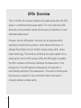
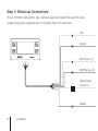
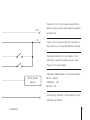
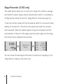
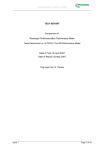
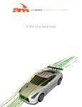
G-100/200 Operation
& Installation
2
Contents
7
Installation
15
Getting Started
16
GPS Mode Setup
18
Wheel Sensor Mode Setup
20
Fuel Calibration
23
Basic Operation
24
Telemetry Screen
27
Entering a Distance
28
Measurement Units
28
Turning On & Off
29
Advanced Features
30
Customising the Telemetry Screen
31
Using the Sprint Timer
32
Auxiliary Inputs
34
Stage Recorder
39
Troubleshooting
3
GPS+ Overview
The G-100/200 can measure distance and speed using either the GPS
signal or a traditional wheel speed sensor. For most customers GPS
alone will provide excellent results with accuracy comparable to a well
calibrated wheel sensor.
However, like any GPS system, accuracy can be degraded when
operating in heavily built-up areas or under dense forest cover. To
address this limitation the G-100/200 includes unique GPS+ sensor
fusion technology. This works by combining the output signals from a
wheel sensor and the GPS receiver. While the GPS signal is available
the GPS+ software continuously calibrates the wheel sensor in the
background. If the GPS signal is subsequently lost operation is
automatically switched to the wheel sensor. The result is uninterrupted
high accuracy operation in any environment without the need to
manually calibrate a wheel sensor.
4
GPS Only
Wheel Sensor Only
GPS+ Sensor Fusion
Mode
Note: To use the GPS+ function simply install a wheel sensor as well as
the GPS antenna. The software will automatically detect the sensor.
5
6
Installation
Warning:
Installation of the G-100/200 may require modifications to be made to
your vehicle’s electrical system. If this is not done correctly, expensive
damage may be caused to both the product and your vehicle. It
is strongly recommended that you seek the services of a qualified
automotive electrician to carry out this work.
7
Step 1: Before You Start
Check that you have the items shown below. You will also need a selection of
tools, wiring equipment, and a suitable place to work.
(A)
(C)
(B)
(A) Rally Computer (B) Wiring Loom
(C) GPS Antenna and/or Wheel Speed Sensor (see page 4)
8
Installation
Step 2: Fitting to the Vehicle
Securely attach the rally computer to the interior of your vehicle. The most
common locations for this are either on the dashboard directly in front of the
co-driver or on the passenger door frame.
When fitting the device, ensure that:
• It will not come free of its mounts during an accident. There are two
M4 bosses on the back that can be used to fasten it securely.
• It does not interfere with any of the vehicle’s safety equipment.
• The co-driver can operate it comfortably while seated.
Warning: If the vehicle still has airbags fitted, do not place the device over the
covers from which these are deployed. Doing so could result in serious injury in
the event of a collision.
Installation
9
Step 3: Electrical Connections
The G-100/200 connects to your vehicle’s electrical system through the colorcoded wiring loom supplied with it. Connect this loom as shown.
RED
BLACK
WHITE (Aux. A)
BROWN (Aux. B)
Speed Sensor
Connector
GREEN
10
Installation
Connect to a 12 Volt power source that is
+12V
0V
able to supply power even when the ignition
is turned off.
Use a common ground point for all parts of
the circuit. Do not use the vehicle’s chassis.
(Optional) Attach up to two hand or foot
switches to use the Auxiliary Inputs. See
Page 12 for more details.
(Optional) Wheel Sensor Connector Details:
Monit Speed
Sensor
BLUE - Signal
ORANGE - +5V
BLACK - 0V
(G-200 only) Connect to the output of your
vehicle’s fuel sender.
Installation
11
GPS Antenna
If GPS is going to be used to measure speed and distance you will need to fit
a suitable antenna. There is a range of these available from Monit. The antenna
attaches to the device using the SMA connector on the back. Refer to the
information supplied with your antenna for detailed instructions.
Wheel Speed Sensor
If GPS is not going to be used, or you want to make use of the GPS+ sensor
fusion technology (see Page 4), you will need to supply a wheel speed signal
to the rally computer. There is a special connector on the wiring loom for this
purpose. It will connect directly to the range of wheel sensors available from
Monit, and detailed installation instructions are supplied with each sensor.
Auxiliary Inputs
These can be used to attach up to two hand or foot switches to the unit. You
can then configure each switch to perform a range of useful functions, such
as clearing the distance or controlling the stopwatch. For most functions a
normally-off momentary type switch should be used.
See page 32 for more information.
12
Installation
Fuel Sender Signal (G-200 only)
To use the G-200’s fuel measurement system, connect the output signal from
your vehicle’s fuel sender directly to the green wire on the loom.
Points to note during installation are:
• The G-200 works by measuring the output voltage of your vehicle’s fuel
sender. It can be used with signals that either rise or fall with increasing
fuel level.
• If you remove your factory fuel gauge you will need to fit a resistor of
approximately the same value in its place to power the sender.
• Many factory fuel senders will not produce an output signal when the
ignition is turned off.
Installation
13
Step 4: Final Checks
Before you apply power to the system check that all your electrical connections
are correct. Also make sure that any exposed wires in the circuit are covered
with insulation tape or heat-shrink so they will not short against the chassis.
14
Installation
Getting Started
Read through this section to learn how to quickly setup and configure
the unit after powering it up for the first time. If you are using GPS
to measure distance and speed go to page 16. If you are using a
traditional wheel speed sensor go to page 18.
15
GPS Mode Setup (default)
Once you have finished installing the unit and GPS antenna apply power to
the unit to start it up. The first menu to appear will prompt you to select an
operating language (you can change this later on). Following this the main
telemetry screen (see page 24) will appear.
GPS
Status
Before any measurements can be made the GPS receiver must first obtain a
satellite signal lock. To indicate the status of this process an icon is shown in
the lower left corner of the telemetry screen. This flashes ‘-GPS-’ when no lock
is available and changes to ‘GPS’ once a signal lock is obtained. Once lock is
established the G-100/200 is ready to use.
16
Getting Started - GPS Mode
Notes:
• During initial power up (cold start), or if the unit has been disconnected
for a long period of time, it may take up to 12 minutes to obtain an initial
satellite lock.
• If GPS+ sensor fusion technology is being used, the wheel sensor will
be used when the GPS signal is not available to provide uninterrupted
operation. It may take 1-2km after startup before the GPS+ system is
initialised.
You can view the status of the GPS system by navigating to the ‘GPS Setup’
item in the main menu.
Getting Started - GPS Mode
17
Wheel Sensor Mode Setup
If you want to use a traditional wheel sensor instead of the GPS system to
measure distance and speed you will have to disable the GPS receiver and
perform a calibration of the wheel sensor against a known distance before the
unit can be used. After powering up the unit and selecting a default operating
language (this can be changed later on) the setup can be performed using the
menu system.
To disable the GPS receiver, select ‘GPS Setup’ in the main menu and toggle
the ‘Enable’ option to the off position.
Next you will need to perform a calibration. If you already know the pulse/km
calibration value for your vehicle, you can also enter this value directly. Refer to
page 36 for details. Otherwise continue to the next page.
18
Getting Started - Wheel Sensor Mode
Distance Calibration
If the GPS is not being used, you will need to perform a calibration of the
wheel speed sensor before it can be used. The device includes a special
calibration wizard that guides you through this process using simple on-screen
instructions.
To calibrate the distance:
1. Find a piece of road with an accurately known distance. Use a distance of
at least one mile/kilometre for best results.
2. From the Main Menu select Calibration > Cal. Distance to start the
calibration wizard.
3. Follow the instructions on the screen.
Note: The device will not lose its calibration if the power supply is disconnected.
Getting Started - Wheel Sensor Mode
19
Fuel Calibration (G-200 only)
The G-200’s fuel measurement system is designed to work with a wide range
of tank sizes and shapes. Before it can be used, the system must be calibrated
to suit your particular vehicle. This is done using a special calibration wizard
that guides you through the process using simple on-screen instructions.
To calibrate the fuel system:
1. Find a safe place to add and remove fuel from your vehicle. To perform
the calibration, you will need enough fuel to fill the tank completely and a
5-10 litre container that you can use to measure the amount of fuel being
added.
2. Empty all the fuel from the tank.
3. From the Main Menu select Calibration > Cal. Fuel to start the calibration
wizard.
4. Follow the instructions on the screen.
20
Getting Started
The calibration wizard works by recording a number of set points as you add
fuel to the tank. For best results:
• Use at least five set points (up to a maximum of ten).
• Add about 5 to 10 litres of fuel between each point
Notes: Many vehicles will not give a correct fuel signal unless the ignition
is turned on. The device will not lose its calibration if the power supply is
disconnected.
Getting Started
21
22
Getting Started
Basic Operation
This section contains information about the features you will most
often use while on a rally event. Read through it to familiarize yourself
with the product’s main functions and to ensure you get the best out
of it while out on a rally stage.
23
Telemetry Screen
This is the main screen that appears when the rally computer is powered up
and is the one you will use most often while on events. It allows you to easily
view your vehicle’s distance, speed, timing and fuel information.
Interval
Distance
Counter
GPS
Status
The upper half of the menu always shows the Interval Distance Counter which
can be reset by pressing the upper right CLR button. The lower half is used
to show all other speed, distance, timing and fuel parameters for your vehicle.
Use the MODE button to cycle through each of these. The parameters available
are described on the next page.
24
Basic Operation
Total Distance Counter
Second distance counter. Hold the CLR button down
for one second to reset.
Current Speed
The current vehicle speed in kph or mph.
Average Speed (G-200 only)
The average vehicle speed since the function was last
reset. This includes any time spent stationary. Hold the
CLR button down for one second to reset.
Maximum Speed
The maximum vehicle speed. Hold the CLR button
down for one second to reset.
Stopwatch
Integrated stopwatch. Use the STRT button to start
and stop timing. Hold the same button down for one
second to clear the time.
Basic Operation
25
Time of Day (G-200 only)
The current time in 24-hour format. Use the SET button
to adjust the value.
Fuel (G-200 only)
The current fuel level in litres or gallons. When the
vehicle is moving the value may fluctuate as the fuel in
the tank moves about.
To reduce clutter, you can disable parameters that you do not want to use. See
page 30 for more information.
Note: Some parameters are disabled by default. You will need to enable them
before they can be selected using the MODE button.
26
Basic Operation
Entering a Distance
In some situations you may want to set one of the distance counters to a
particular starting value. To do this:
1. Select the Set Distance menu.
2. Choose the counter (Interval or Total) that you want to set.
3. Enter the new value. Use the ‘+’ and ‘-’ buttons to adjust the highlighted
digit and the ‘>’ button to move between digits. When the last digit is
reached press the SET button to finish.
The Set Interval menu can also be accessed by holding down the interval
distance CLR button (top right) for three seconds when in the Telemetry
Screen.
Basic Operation
27
Measurement Units
The device can display distance and fuel information in a number of different
measurement units. To change this select Settings > Units. The device does
not need to be re-calibrated when these settings are changed.
Backlight Intensity
When in the Telemetry Screen the intensity of the backlight can be reduced by
holding down the MENU button for one second. Repeating this will return it to
full brightness. It can also be adjusted by selecting Settings > Backlight.
Turning On & Off
The device turns off automatically after five minutes of inactivity. Press any of
the buttons or start moving the vehicle to turn it on again. This timer can be
disabled if required (see page 37).
28
Basic Operation
Advanced Features
Once you’ve mastered the basic functions of the G-100/200, read
this section to learn about its more advanced features. Customise the
user interface, setup a foot switch and measure the performance of
your vehicle—quickly and conveniently.
29
Customising the Telemetry Screen
The lower half of the Telemetry Screen can be used to display up to seven
different speed, distance, timing and fuel parameters. To reduce clutter the
device allows you to select which parameters you want to use.
To enable or disable a parameter select Settings > Telemetry. A list of available
parameters will appear and selecting one will toggle its status on and off.
30
Advanced Features
Sprint Timer
The built-in Sprint Timer can be used to accurately measure your vehicle’s
0-100kph (0-60mph) and 0-400m (1/4 mile) * acceleration times.
To use the Sprint Timer:
1. Select the Performance menu.
2. Choose the type of sprint you want (0-100kph or 400m*).
3. Bring the vehicle to a halt and press OK to arm the system.
4. The timer will start automatically when the vehicle starts moving. When
the target speed or distance is reached it will stop and display the
acquired time.
* Available on G-200 model only.
Advanced Features
31
Auxiliary Inputs
The two Auxiliary Inputs can be used to attach external hand or foot switches
to the rally computer. These can then be configured in software to perform one
of the tasks shown in the table on the next page.
To assign a task to an input:
1. Select the Settings menu.
2. Select Auxiliary A or Auxiliary B (depending on which switch you want to
configure).
3. Select the task you want from this list and press OK.
32
Advanced Features
Task Name
Description
None
The Auxiliary Input is not used.
Clear Interval
Clears the Interval Distance.
Clear Total
Clears the Total Distance.
Pause
Toggles distance counting on and off.
Freeze
Toggles Freeze mode on and off. When Freeze mode is active,
the display is not updated but the counters continue to operate in the background.
Stopwatch
Controls the stopwatch.
Display Mode
Same effect as the MODE button in the Telemetry Screen.
Backlight Dim
When the input is held low the backlight intensity is reduced.
Count Up/Dn
When the input is held low the distance counters will count
down.
* Stage Recorder
See page 34.
* Speed Alarm
See page 35.
* Available on G-200 model only.
Advanced Features
33
Stage Recorder (G-200 only)
This useful feature allows you to record your stage time, distance, average
and maximum speed values using an external input switch. It is enabled by
configuring the Auxiliary B input for ‘Stage Record’ mode (see page 32).
To use the recorder press and hold the external switch for one second while
waiting on the start line. This will arm the system and clear the counters
and stopwatch. When the vehicle begins moving the stopwatch will start
automatically. At the end of the stage press the switch again and the stage
information will be displayed and recorded.
You can review the last stage’s information at anytime by navigating to the
‘Stage Record’ display in the main menu.
34
Advanced Features
Speed Alarm (G-200 only)
The Auxiliary A port can be used to drive a warning light when the vehicle
exceeds a programmable speed. This is ideal for events with speed controls or
on touring stages.
To activate the feature configure the Auxiliary A port in ‘Speed Alarm’ mode
(see page 32) and fit a Monit warning light (available separately). Once this is
done a new icon will appear in the main menu allowing you to set the trigger
speed and enable or disable the alarm.
Advanced Features
35
Calibration Value Adjustment (GPS disabled)
In wheel speed sensor mode the calibration value is stored as the number
of pulses produced for every kilometre/mile travelled. If you share the device
between vehicles, or change tyre sizes frequently, you may want to view and
edit this value manually.
To view the calibration value select Calibration > Value.
To edit the calibration value (only possible if GPS is disabled):
1. Select Calibration > Value.
2. Press the EDIT button.
3. Enter the new value. Use the ‘+’ and ‘-’ buttons to adjust the highlighted
digit and the ‘>’ button to move between digits. When the last digit is
reached press the SET button to finish.
36
Advanced Features
Counting Direction
The distance counters can be configured to count either up or down. To
change the direction select Settings > Advanced > Counting. You can also use
an external switch to control this setting (page 32).
Display Resolution
The distance counters normally have a resolution of ten metres. If you require
a higher level of accuracy this can be increased to one metre. To change this
select Settings > Advanced > Resolution.
Sleep Timer
The device will automatically enters a low power sleep mode after five minutes
of inactivity. This can be adjusted by selecting Settings > Advanced > Sleep.
Note: Take care to ensure your vehicle’s battery does not run flat if you disable
the Sleep Timer.
Advanced Features
37
Restoring Factory Defaults
To restore all settings to their default factory values navigate to the About menu
and hold down the two buttons on the right of the screen for five seconds.
Warning: You will lose all calibration values when this is done.
38
Advanced Features
Troubleshooting
If you’re having trouble getting fuel or distance measurements
working, read through this section for solutions to some common
problems. And if you can’t find an answer here, don’t hesitate to
contact Monit directly for help.
39
Common Problems:
I’m using a wheel sensor and the distance measurements are not
consistent / increment while stationary.
When GPS is disabled the G-100/200 measures distance by counting the
pulses produced by a wheel speed sensor. Noise from other parts of your
vehicle’s electrical system can interfere with this signal and cause measurement errors.
To solve the problem:
• Ensure that the G100/200, speed sensor and any attached switches
are all grounded directly to a ground point on the vehicle’s engine
management computer. Do not use the vehicle’s chassis.
• Physically move the G-100/200 wiring away from other wires in your
vehicle.
40
Troubleshooting
The fuel level changes when I turn my engine on and off
The output signal from some fuel senders is proportional to the vehicle’s battery
voltage. When the engine is running this voltage is boosted by the alternator
and this can cause changes in the fuel reading.
To solve the problem:
• If you will usually be checking the fuel level when the engine is running,
calibrate the system with the engine running.
• Some after-market fuel senders will not have this problem. Check if your
local motorsport dealer has a sender with a more stable output.
The fuel level measurements are not accurate
If the fuel sender in your vehicle does not generate a good quality signal, the
G-200 will not be able to make accurate measurements. Unfortunately many
factory senders are designed for low cost not accuracy and you may have to fit
an after-market sensor if you require better performance.
Troubleshooting
41
Error Messages:
‘Error: No pulses detected’— No pulses are being detected from the wheel
speed sensor during calibration. Check your connections and the instructions
supplied with the sensor.
‘Error: Too many pulses’ — Too many pulses are being generated by the
wheel speed sensor during calibration. Fit a pulse divider unit (available from
Monit). This error can also be caused by electrical interference (see page 40).
‘Error: Level must increase between set points.’— The amount of fuel you
specified for this set point is less than what you specified for the previous one.
Check your calculations.
‘Error: Maximum number of set points reached.’— The G-200 can store
a maximum of ten fuel set points. Repeat the calibration using an increased
amount of fuel between each set point.
42
Troubleshooting
‘Error: Invalid Fuel Signal. Refer to user’s manual.’— The fuel sender is not
producing a monotonic (doesn’t move in one direction) output signal during
calibration.
To solve the problem:
• On many factory fuel tanks the fuel sensor is not very sensitive. Repeat
the test but this time add more fuel between each set point.
• The fuel may take some time to settle in the tank when added. Repeat the
calibration but this time wait at least 30 seconds after adding fuel before
you record each set point.
Also note that some senders will not produce an output signal unless the
vehicle’s ignition is turned on.
Troubleshooting
43
© Monit Limited
http://www.monitrally.com