1
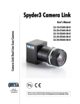
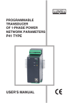
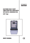
NUMERICAL DIGITAL DISPLAY PANEL DNL2 AND DNL3 TYPE USER’S MANUAL 1 USE R'S MA NUA L DNL2 - 09 Contents 1 Application............................................................................................................................3 2 Display panel set..................................................................................................................3 3 Basic requirements, operational safety................................................................................3 4 Design description and installation.......................................................................................4 5 Electrical connections...........................................................................................................5 6 Display panel configuration..................................................................................................6 6.1 Turning the display panel on.........................................................................................6 6.2 Modification of transmission parameters......................................................................6 6.3 Display configuration.....................................................................................................7 6.3.1 Display format..........................................................................................................7 6.3.2 Displayed value – displayed registers.....................................................................7 6.3.3 Rescaling displayed value – individual characteristic..............................................7 6.3.4 Minimum and maximum displayed value and alarms..............................................8 6.3.5 Error messages........................................................................................................8 6.4 Display luminosity setting..............................................................................................9 6.5 Date and time settings..................................................................................................9 6.6 Display panel configuration for readout data from analog input...................................9 6.7 Display panel configuration for readout data from additional devices........................10 7 Interface..............................................................................................................................11 7.1 RS485 programming interface....................................................................................11 7.2 Registers 4000..4050..................................................................................................12 7.3 Registers 4300..4359..................................................................................................14 7.4 Registers 7000..7282 and 7500..7645........................................................................16 8 Technical data.....................................................................................................................19 9 Order code..........................................................................................................................20 10 Before a failure will be declared.......................................................................................21 11 Maintenance and service..................................................................................................21 US E R'S MA NUA L DNL 2 -09 3 1 Application LED DNL digital display panels are designed for display of digital values indoor: offices, manufacturing plants or production supervision points, providing information such as production parameters, machine condition, device operational status etc. DNL display panels can be configured with LPCon software application available for free on the website www.lumel.com.pl. DNL display panels are equipped with two RS485 communication interfaces using MODBUS RTU standard. First interface (programming interface) is used for the configuration of the display panel settings or for the input of displayed value (the display panel is a Slave device in MODBUS RTU network) e.g. from the SCADA application or PLC drivers Second interface (object interface) is used for plugging slave devices (the display panel is a Master device in MODBUS RTU network) the display panel gets displayed data from. Display panel configuration allows reading up to 100 registers from slave devices (up to 10 registers per each of 10 devices, see Table 5), so the display panel can act as the local data collection point All data received from slave devices can be accessed as internal registers of the display panel for the SCADA application or PLC drivers via RS485 MODBUS RTU Slave interface. It is possible to define minimum and maximum displayed value for the display panels. Additionally, the display panel may be equipped with auxiliary measurement input for the measuring of standard analog signal 4..20 mA used in automatics and with output powering external measurement transducers. Basic configuration of the display panel includes one or two fields for readings (4 digits each) and space for the unit placement. 2 Display panel set Complete set of the meter includes: DNL digital display panel Fitting brackets Instructions manual Warranty card 1 pc 2 pcs 1 pc 1 pc 3 Basic requirements, operational safety Display panel conforms to a safety standard EN 61010-1. Display panel should be installed and connected only by a qualified personnel. All relevant safety measures should be observed during installation. Always check electric connections before turning the device on. Do not mount a display panel outside of the buildings. Display panel must be used only for intended purposes. Removing the outer housing of the display panel during warranty period voids the warranty. When connecting panel to the power source, make sure that the electric system of the building includes manual or automatic circuit breaker. This element should be close to the device, within the reach of an operator and marked as a breaker for switching the device off. US E R'S MA NUA L DNL 2 -09 4 4 Design description and installation DNL digital display panels are enclosed in a housing made of aluminium profiles providing IP40 protection (IP10 on the terminals side). Overview and dimensions of the display panels are presented on the Fig. 1 One row version Two rows version DNL-2 [mm] DNL-3 [mm] DNL-2 [mm] DNL-3 [mm] A 931 1091 931 1091 B 905 1065 905 1065 C 868 1027 868 1027 D 328 414 609 781 E 281 367 562 734 Fig. 1. Overview and dimensions of one row and two rows display panel. US E R'S MA NUA L DNL 2 -09 5 The housing allows the display panel to be fitted to a wall or suspended from a ceiling, angle of suspended panel may be adjusted. 5 Electrical connections Connection of the power and interface wires should only be done according to the manual. Shielded stranded cable should be used for control signals connections. It is allowed to use unshielded stranded cable if the surroundings are characterized by low interference level. Caution! In the case of rapid temperature change that may cause water condensation, a display panel should not be connected to a supply. It is recommended to wait at least 60 minutes before installation of the display panel that was subjected to the rapid temperature shift. Connectors are located on the back side of the display panel. Description of the connector signal is shown on the fig. 2. Fig. 2. Display connection diagram Fig. 2. Display connection diagram Object interface and programming interface are galvanically separated. Object interface is used to connect slave devices and programming interface is used to connect the display panel to RS485 bus (with a display panel used as a slave device), i.e. to PLC driver, PC, data concentrator etc. Analog input 4..20 mA is used for connecting external signal, i.e. from measurement transducer. Additionally, board with analog input has +15 V power connector supplying power to external measurement transducers. After switching a device on, a panel performs a display test and then proceeds to display the value found in the register 7500 (value readout from the device 1). It is possible to change the displayed value by changing a panel configuration. US E R'S MA NUA L DNL 2 -09 6 6 Display panel configuration Panel display settings can be configured by the programming interface. To program the desired display parameters one may use the LPCon application of any program allowing for reading and modification of the registers of any MODBUS RTU device. Default setting of the display panel: address: 1, baud rate: 9600 bits per second transmission mode: RTU 8n2. Mapping and description of registers are presented in section 7 – “Interface”. 6.1 Turning the display panel on After DNL display panel is turned on, display test is performed and the panel displays information regarding programming interface transmission parameters. Example of transmission parameters display is shown on the Fig.3. Interface address No1 - interface for programming Address: 125 Operation mode of interface No1: 0: RTU 8N1 1: RTU 8N2 2: RTU 8E1 3: RTU 8O1 Baud rate of interface No 1 [b/s]: 0 - 2400; 1 - 4800; 2 - 9600; 3 - 14400; 4 - 19200; 5 - 28800; 6 - 38400; 7 - 57600; 8 - 76800; 9 - 115200 Fig. 3. Transmission parameters display. 6.2 Modification of transmission parameters Transmission parameter may be changed through modification of the driver registers 4000..4002. Required values should be entered into the registers 4000..4002 and then a value of 1 should be entered into the register 4004. This stores the new parameters and allows the display panel to use all entered values. It is recommended to store old and new transmission parameters, so the US E R'S MA NUA L DNL 2 -09 7 transmission might be restored in case of problems. Caution! After the transmission parameters are changed, corresponding changes must be made in the software used together with the display panel. Additionally it might also be necessary to reconfigure transmission transducer if they are connected between the computer and the display panel. 6.3 Display configuration DNL display panel allows the display of numerical values in selected format (with a set accuracy). Prior to displaying, value might be rescaled according to the linear function. Rescaled value is inserted in the register that can be readout by the programming interface. Display parameters are changed by the modification of the configuration registers of the display panel driver. Below you can find detailed description of the display configuration for one row display panel. In the case of two rows display panel, configuration procedure is not changed (see register map in the ‘Interface’ section). 6.3.1 Display format Displayed numerical value may be shown with the specified accuracy (decimal places). Display format is modified through changing of the register 4019 for the first row, register 4023 for the second row etc. Value entered into the register defines number of the decimal places. 6.3.2 Displayed val ue – displayed registers Displayed registers are the basic configuration parameters of the display panel. They define values to be displayed in the separate rows of the display panel. DNL display panel can display values stored in registers 7500..7645. Displayed register is changed through the modification of the 4020 register for the first row and register 4024 for the second row. These registers store the shift value in reference to the register 7500. Shift can calculated using this formula: S = DR – 7500 where: S – shift, DR – displayed register (7500..7645). Example We want to display the third register readout from the device 2 (register 7512), thus DR = 7512. S = 7512 – 7500 = 12 To achieve this, a value of 12 must be stored in the register 4020 (register of the display present at the 7512 address will be displayed). User can configure the display panel to display following values: readout from the attached devices (registers 7500..7599); stored in the general registers stored after the power is turned off (registers 7600..7609); stored in general registers that are not saved after the power is turned off (registers 7610..7619); stored in registers of values to be displayed (registers 7636..7639); at the analog input 4..20 mA (registers 7642 or 7645). Numerical value from the master continuously storing data in the display panel should be displayed using the registers 7610..7619 (shift 110..119). The value will not be stored. When panel is turned on, an upper limit overrun message will be displayed until a new value is entered. This feature protects the non-volatile memory from excessive number of writing operation. 6.3.3 Rescaling displayed value – individual characteristic Prior to display, every value may be recalculated relative to the applied linear characteristic. Factors used in value recalculation are stored in the registers 7622, 7623 (for the first row) and 7626, 7627 (for the second row). To recalculate values prior to display, user must enter factors a and b. Displayed value will be calculated according to formula: DV = RV *a + b US E R'S MA NUA L DNL 2 -09 8 where: a and b are formula factors, DV – displayed value, RV – value stored in the displayed register. Additionally, the result (DV) is stored in the register 7636 that can be readout by the master. Example Display panel is configured to readout data from P18 transducer. Temperature is readout in degrees Celsius, but it is needed to be displayed in degrees Fahrenheit. Using formula for temperature calculation we have: °F = (°C × 1.8) + 32 Thus factor a = 1.8 and factor b = 32. So we must but the following values in the registers: 7622 = 1.8 (row 1 – factor „a” of the individual characteristic); 7623 = 32 (row 1 – factor „b” of the individual characteristic); 6.3.4 Minimum and maximum displayed value and alarms User may set a limit for the minimum and maximum value displayed by the display panel by entering required limit values to the registers 7620, 7621 (for the first row) and 7624, 7625 (for the second row). Whenever the value to be displayed is lower than the value stored in the register 7620 (for the first row), the display panel will show lower overrun message ___ (see Table 1) . This message will also be displayed if the value is too low to be physically displayed. Whenever the value to be displayed is higher than the value of the upper limit (register 7621 for the first row), the display panel will show upper overrun message ‾‾‾‾‾ (see Table 1). This message will also be displayed if the value is too high to be physically displayed. Using minimum and maximum values, user can easily define range of indications. Caution! In case of incorrect values set for minimum and maximum limit it is possible that the display panel permanently displays an error message. It should be noted that minimum and maximum values that can be displayed also depend on the selected format. Table 1 Warning Lower overrun Symbol Upper overrun Warning description Value is lower than the programmed minimal value or is too small to be displayed (too many digits to fit in the display panel, e.g. -9850). Value is higher than the programmed minimal value of is too large to be displayed (too many digits to fit in the display panel, e.g. 21253). Overrun indication may be further emphasized by enabling alarm function for the separate rows (register 4021 for the first row and register 4025 for the second row). This causes overrun messages to pulse. 6.3.5 Error messages DNL display panel implements a function of displaying an error preventing required value to be displayed. This message is presented below. Table 2 Warning Symbol Slave device communication error Warning description Value to be displayed is acquired from a device which there is no communication with. The device does not respond properly or configuration of a communication with the device is incorrect. This message is displayed after 5 subsequent failed attempts to readout the value. US E R'S MA NUA L 6.4 DNL 2 -09 9 Display luminosity setting DNL display panels are equipped with automatic luminosity control (build-in lighting sensor). With automatic luminosity control enabled (register 4013 = 1) it is possible to set maximum luminosity value (register 4014) and minimum luminosity value (register 4015). User can also set luminosity to change at specific hours. This setting uses internal real-time clock of the display panel. To change luminosity parameters it is necessary to modify registers 4013..4017. Luminosity level is set as a percentage, so its range is: 1..100 (registers 4013, 4014). Beginning of the day (register 4016, hour * 100 + minutes) and beginning of the night (register 4017, hour *100 + minutes) define the period of luminosity settings. Period from the register 4016 to 4017 sets the day luminosity and period from the register 4017 to 4016 sets the night luminosity. Example Setting the automatic luminosity control. Maximum luminosity is set to 100%, minimum luminosity is set to 20%. This means, that following values must be stored in registers: 4013 = 1 (0 – sensor off, 1 – lighting sensor on); 4014 = 100 (maximum luminosity in the automatic luminosity mode); 4015 = 20 (minimum luminosity in the automatic luminosity mode). Example Day luminosity is set to 100%, night luminosity is set to 10% with day begins at 6:30 am and night beginning at 3:45 pm So we must but the following values in the registers: 4013 = 0 (0 – sensor off, 1 – lighting sensor on); 4014 = 100 (day luminosity); 4015 = 10 (night luminosity); 4016 = 630 (beginning of the day 4016 = hour * 100 + minutes); 4017 = 1545 (beginning of the night 4017 = hour * 100 + minutes); 6.5 Date and time settings To set proper internal RTC clock used for timed luminosity regulation, an actual time must be stored in the registers: 4008..4012. Daylight saving time may be also enabled, if necessary. Example It is 2011-03-18, 15:15:00 with daylight saving time enabled. Following values must be stored in respective registers: 4008 = 1 (0 – DST off, 1 – DST on); 4009 = 0 (seconds); 4010 = 1515 (4010 = hour * 100 + minutes 0); 4011 = 318 (4011 = month * 100 + day); 4012 = 2011 (year); 6.6 Display panel configuration for readout data from analog input DNL display panel with an analog input may be configured to measure current signal 4..20mA, e.g. from the external temperature transducer. DNL display panel is equipped with an additional function allowing for rescaling the measurement acquired from the analog input. To enable it, proper values must be stored in registers 7643 and 7644. Example Assume that temperature transducer is connected to the measurement input of the display panel. The -10°C signal corresponds to the 4 mA current and the 150°C signal corresponds to the 20 mA. To show actual temperature and not the transducer current value, it is necessary to define rescaling factors a and b of the Y=aX+b function X1 = 4 mA (measured value) X2 = 20 mA (measured value) Y1 = -10°C (measured value) Y2 = 150 °C (measured value) US E R'S MA NUA L DNL 2 -09 10 a = (Y2-Y1)/(X2-X1) = (150-(-10))/(20-4) = 10 b = y1 – a * x1 = -10-10*4 = -50 So, following values must be entered into respective registers: 7643 = 10 (rescaling factor „a” for input 1); 7644 = -50 (rescaling factor „b” for input 1); Additionally, it is necessary to set displayed value limits for a given row. For the first row: r egisters 7620 and 7621 : 7620 = -10(row 1 – lower displayed value limit. For values lower than this value a lower overrun message is displayed). 7621 = 150(row 1 – upper displayed value limit. For values higher than this value an upper overrun message is displayed). To display the measured value after rescaling in the first row, a following value should be entered into register 4020: 4020 = 145 (number of registry to display, as a shift relative to 7500 address). 6.7 Display panel configuration for readou t data from additional devices DNL display panel may be configured to display and readout data from additional devices working in MODBUS RTU mode. All additional devices and DNL display panel should have the same transmission parameters, i.e. speed and mode. Additional devices should have different addresses. Device address, register type which a readout starts from (base register), number of registers and query frequency are individually programmed for any additional device. Configuration of data readout from external devices means setting: object interface transmission parameters: baud rate and frame mode should be identical for object interface and devices connected to the display panel. Response waiting time should be adjusted for the longest response time of the slowest device connected to the object interface. Transmission parameters are configured in registers 4005..4007; device address (register 4300 for the first device): it is necessary to enter address of the device which data are readout from. Entering 0 as an address disables readout from the device. Caution: All connected devices must have unique address, so no two devices in the network share the same address; base register (register 4301 for the first device): register address which should be readout from (according to the register map of additional device); register number (register 4302 for the first device): sets the number of registers to be readout from the device; register type (register 4303 for the first device): defines type of data in the registers to be readout. DNL display panel supports following register formats: char, unsigned char, integer, unsigned integer, long, unsigned long, float; query frequency (register 4304 for the first device); Defines time between subsequent readout for the device; readout function in the MODBUS mode (register 4305 for the first device): defines MODBUS command (03 or 04) used for querying register of an additional device. Display panel queries all configured and connected devices and puts all readout data in its registers (7500..7599). Data readout is performed according to set query frequency. When querying slow devices, querying time may exceed programmed value due to long device response time. In a case the device fails five subsequent queries, a communication error flag will be set for this device (Device status register 4045) and registers of readout values from this device will be reset to 1E+20 until communication with the device is resumed. Example Object interface has a P18 humidity and temperature transducer attached, transducer address is 1 and transmission parameters: RTU frame type 8n2, baud rate 9600, it is used for temperature and humidity readout. Transducer is configured as device no. 1. To configure the device, registers must be configured as follows: US E R'S MA NUA L DNL 2 -09 11 4005 = 1 (frame type: RTU 8n2); 4006 = 2 (baud rate at 9600); 4007 = 5 (response waiting time: 500ms); 4300 = 1 (device address); 4301 = 7501 (device base register); 4302 = 2 (number of registers – temperature and humidity readout) 4303 = 6 (register type: float); 4304 = 1 (query frequency – every second). For transducer configured as above, temperature and humidity values will be readout from P18 transducer every second and then stored in registers 7500 (temperature) and 7501 (humidity). To display readout values e.g. in first row, it is necessary to enter 0 for temperature or 1 for humidity in register 4020. 7 Interface DNL display panel is equipped with two MODBUS RTU RS485 communication interfaces: Programming interface – for connecting the display panel to the master device, e.g. computer, PLC driver etc. This interface is used for display panel configuration and may be used for string values for display (use of general registers). Object registers – for connecting additional devices, such as measuring devices, transducers, drivers etc. used as the source for data to be readout and displayed if needed. This interface uses the display panel as a master device. DNL display panel uses following MODBUS function for communication: Function 03 – readout of n registers, where n is the number of registers to be readout. Function 06 – writing to a single register, Function 16 – writing to n registers, (where n is the number of registers to be written). Function 17 – device identification. Data readout from additional devices uses 03 and 04 MODBUS functions. 7.1 RS485 programming interface Parameters summary: - identifier 0xCA, - transducer address 1..247, - baud rate 2.4, 4.8, 9.6, 14.4, 19.2, 28.8, 38.4, 57.6, 76.8, 115.2. kbit/s, - operation mode Modbus RTU, - transmission mode 8N2, 8E1, 8O1, 8N1, - maximum response time 400 ms, - maximum number of readout registers in a single query: 56 – for 4-byte registers, 102 – for 2-byte registers, - implemented functions 03, 06, 16, 17, - 03 register readout, - 06 single register writing, - 16 writing of n registers, - 17 device identification. Manufacturer’s settings: address 1, speed 9600 baud, 8N2 RTU mode. Table 2 Address range 4000 – 4050 4300 – 4359 7000 - 7290 Value type Description Integer (16 bits) Integer (16 bits) Value set in the 16-bit register. Description of registers is shown in Table 3. Registers for writing and readout. Value set in the 16-bit register. Description of registers is shown in Table 4. Registers for writing and readout. Value is set in the two following 16-bit registers. Registers contain exactly the same data, as 32-bit registers of 7500 – 7641 range. Readout registers. Bit sequence (3-2-1-0) Float (2x16 bits) US E R'S MA NUA L DNL 2 -09 7500 – 7645 7.2 12 Float (32 bits) Value set in the 32-bit register. Description of registers is shown in Table 5. Readout registers. Registers 4000..4050 16-bit unsigned integer registers – display panel configuration. Table 3 Operation Register address s 4000 RW 4001 RW 4002 RW 4003 - 4004 RW 4005 RW 4006 RW 4007 RW 4008 4009 4010 4011 4012 RW RW RW RW RW 4013 RW 4014 RW 4015 RW 4016 4017 RW RW 4018 4019 RW RW 4020 RW 4021 RW 4022 4023 RW RW 4024 RW 4025 4026...4033 RW R 4034 RW Range 1…247 Description Interface 1 address – programming interface Interface 1 operation mode 0: RTU 8N1 0…3 1: RTU 8N2 2: RTU 8E1 3: RTU 8O1 Interface no. 1 baud rate [b/s]: 0 – 2400; 1 – 4800; 2 – 9600; 3 – 14400; 0…9 4 – 19200; 5 – 28800; 6 – 38400; 7 – 57600; 8 – 76800; 9 – 115200 reserved Update programming interface transmission 0..1 parameters Interface 2 operation mode 0: RTU 8N1 0…3 1: RTU 8N2 2: RTU 8E1 3: RTU 8O1 Interface no. 2 baud rate [b/s]: 0 – 2400; 1 – 4800; 2 – 9600; 3 – 14400; 0…9 4 – 19200; 5 – 28800; 6 – 38400; 7 – 57600; 8 – 76800; 9 – 115200 Response time for slave device on port 2 is a 1…50 multiple of 100 ms Time and date 0..1 0 - DST off, 1 - DST on 0..59 Seconds 0...2359 Hour*100 + Minutes 0 101…1231 Month * 100 + day 2000...2100 Year Display luminosity 0..1 0 - off, 1 - lighting sensor on Luminosity for the day, maximum luminosity 1…100 (maximum luminosity in the automatic mode) Luminosity for the night, minimum luminosity 1…100 (minimum luminosity in the automatic mode) 0000…2359 Beginning of day hour*100 + Minutes 0000…2359 Beginning of night hour*100 + Minutes Display panel row configuration Row no. I 1…20 Number of digits in the first row 0…3 Display format – decimal places Number of register for display as the shift relative 0…145 to address 7500. 0.1 Alarm on. Row no. II 0…20 Number of digits in the second row 0…3 Display format – decimal places Number of register for display as the shift relative 0…145 to address 7500. 0.1 Alarm on. Reserved registers Auxiliary registers 0..65535 Storing integer in the register puts the integer in US E R'S MA NUA L DNL 2 -09 4035 RW 4036 RW 4037 RW 4038 RW 4039 RW 4040 RW 4041 RW 4042 RW 4043 RW 4044 R 4045 R 4046 RW 4047 RW 4048 4049 4050 R R R N/A - not applicable 13 the register 7610. Storing integer in the register puts the integer in 0..65536 the register 7611. Storing integer in the register puts the integer in 0..65537 the register 7612. Storing integer in the register puts the integer in 0..65538 the register 7613. Storing integer in the register puts the integer in 0..65539 the register 7614. Storing integer in the register puts the integer in 0..65540 the register 7615. Storing integer in the register puts the integer in 0..65541 the register 7616. Storing integer in the register puts the integer in 0..65542 the register 7617. Storing integer in the register puts the integer in 0..65543 the register 7618. Storing integer in the register puts the integer in 0..65544 the register 7619. System registers Status – subsequent bits are event flags: bit 15 – maintenance mode – requires maintenance authorization; bit 14 – EEPROM memory error – factory settings restored; bit 13 – RTC settings error or settings are ambiguous; bit 12 – Daylight saving time turned on or off; N/A bit 11 – External light sensor error (only for a version with a sensor); bit 10 – Power outage; bit 09 – bus 2 measurement error – value out of range; bit 08 – bus 1 measurement error – value out of range; bits 07…00 – not used – value always set to 0. Status of the devices connected to the display panel, subsequent bits show slave devices transmission status: bit 15 - transmission errors occurred; bit 09 - device 10 error; bit 08 - device 9 error; bit 07 - device 8 error; N/A bit 06 - device 7 error; bit 05 - device 6 error; bit 04 - device 5 error; bit 03 - device 4 error; bit 02 - device 3 error; bit 01 - device 2 error; bit 00 - device 1 error; N/A Safety password (4321) Order (safety password required): N/A 0x8000 – restore factory settings; 0x4000 – perform display panel test; 0..65544 Serial number two older bytes 0..65544 Serial number two younger bytes 0..65544 Program version /100 US E R'S MA NUA L 7.3 DNL 2 -09 14 Registers 4300..4359 16-bit unsigned integer registers – configuration of readout from connected devices. Table 4 Operation Register address s 4300 4301 4302 RW RW RW 4303 RW 4304 RW 4305 RW 4306 4307 4308 4309 RW RW RW RW 4310 RW 4311 RW 4312 4313 4314 4315 RW RW RW RW 4316 RW 4317 RW 4318 4319 4320 4321 RW RW RW RW 4322 RW 4323 RW Range Description Device no. 1 0.1…247 Slave device address. 0 – turns device off 0…65535 Base register. 1…10 Number of readout registers Register type: 0 – char variable 1 – unsigned char variable 2 – integer variable 3 – unsigned integer variable 4 – long variable 5 – unsigned long variable 6 – float variable 7 – long variable as 2x16bit (1234) 8 – long variable as 2x16bit (2143) 0…6 9 – long variable as 2x16bit (4321) 10 – long variable as 2x16bit (3412) 11 – u. long variable as 2x16bit (1234) 12 – u. long variable as 2x16bit (2143) 13 – u. long variable as 2x16bit (4321) 14 – u. long variable as 2x16bit (3412) 15 – float variable as 2x16bit (1234) 16 – float variable as 2x16bit (2143) 17 – float variable as 2x16bit (4321) 18 – float variable as 2x16bit (3412) Query frequency in seconds. Determines query 1…60 frequency for slave device. Readout function in MODBUS mode: 0..1 0 - function 03 1 - function 04 Device no. 2 0.1…247 Slave device address. 0 – turns device off 0…65535 Base register. 1…10 Number of readout registers 0…6 Register type: (as per device 1) Query frequency in seconds. Determines query 1…60 frequency for slave device. Readout function in MODBUS mode: 0..1 0 - function 03 1 - function 04 Device no. 3 0.1…247 Slave device address. 0 – turns device off 0…65535 Base register. 1…10 Number of readout registers 0…6 Register type: (as per device 1) Query frequency in seconds. Determines query 1…60 frequency for slave device. Readout function in MODBUS mode: 0..1 0 - function 03 1 - function 04 Device no. 4 0.1…247 Slave device address. 0 – turns device off 0…65535 Base register. 1…10 Number of readout registers 0…6 Register type: (as per device 1) Query frequency in seconds. Determines query 1…60 frequency for slave device. 0..1 Readout function in MODBUS mode: US E R'S MA NUA L DNL 2 -09 4324 4325 4326 4327 RW RW RW RW 4328 RW 4329 RW 4330 4331 4332 4333 RW RW RW RW 4334 RW 4335 RW 4336 4337 4338 4339 RW RW RW RW 4340 RW 4341 RW 4342 4343 4344 4345 RW RW RW RW 4346 RW 4347 RW 4348 4349 4350 4351 RW RW RW RW 4352 RW 4353 RW 4354 4355 4356 4357 RW RW RW RW 4358 RW 4359 RW 15 0 - function 03 1 - function 04 Device no. 5 0.1…247 Slave device address. 0 – turns device off 0…65535 Base register. 1…10 Number of readout registers 0…6 Register type: (as per device 1) Query frequency in seconds. Determines query 1…60 frequency for slave device. 0..1 Readout function in MODBUS mode: 0 - function 03 1 - function 04 Device no. 6 0.1…247 Slave device address. 0 – turns device off 0…65535 Base register. 1…10 Number of readout registers 0…6 Register type: (as per device 1) Query frequency in seconds. Determines query 1…60 frequency for slave device. 0..1 Readout function in MODBUS mode: 0 - function 03 1 - function 04 Device no. 7 0.1…247 Slave device address. 0 – turns device off 0…65535 Base register. 1…10 Number of readout registers 0…6 Register type: (as per device 1) Query frequency in seconds. Determines query 1…60 frequency for slave device. 0..1 Readout function in MODBUS mode: 0 - function 03 1 - function 04 Device no. 8 0.1…247 Slave device address. 0 – turns device off 0…65535 Base register. 1…10 Number of readout registers 0…6 Register type: (as per device 1) Query frequency in seconds. Determines query 1…60 frequency for slave device. 0..1 Readout function in MODBUS mode: 0 - function 03 1 - function 04 Device no. 9 0.1…247 Slave device address. 0 – turns device off 0…65535 Base register. 1…10 Number of readout registers 0…6 Register type: (as per device 1) Query frequency in seconds. Determines query 1…60 frequency for slave device. 0..1 Readout function in MODBUS mode: 0 - function 03 1 - function 04 Device no. 10 0.1…247 Slave device address. 0 – turns device off 0…65535 Base register. 1…10 Number of readout registers 0…6 Register type: (as per device 1) Query frequency in seconds. Determines query 1…60 frequency for slave device. 0..1 Readout function in MODBUS mode: 0 – function 03 1 – function 04 US E R'S MA NUA L 7.4 DNL 2 -09 16 Registers 7000..7282 and 7500..7645 32-bit float registers. Table 5 Registers address 2 x 16 bits 32-bit register address Operations 7000 7002 7004 7006 7008 7010 7012 7014 7016 7018 7020 7022 7024 7026 7028 7030 7032 7034 7036 7038 7040 7042 7044 7046 7048 7050 7052 7054 7056 7058 7060 7062 7064 7066 7068 7070 7072 7074 7076 7078 7080 7082 7084 7086 7088 7090 7092 7094 7096 7098 7100 7102 7500 7501 7502 7503 7504 7505 7506 7507 7508 7509 7510 7511 7512 7513 7514 7515 7516 7517 7518 7519 7520 7521 7522 7523 7524 7525 7526 7527 7528 7529 7530 7531 7532 7533 7534 7535 7536 7537 7538 7539 7540 7541 7542 7543 7544 7545 7546 7547 7548 7549 7550 7551 R R R R R R R R R R R R R R R R R R R R R R R R R R R R R R R R R R R R R R R R R R R R R R R R R R R R Description Readout values Device 1 – First register readout. Device 1 – Second register readout. Device 1 – Third register readout. Device 1 – Fourth register readout. Device 1 – Fifth register readout. Device 1 – Sixth register readout. Device 1 – Seventh register readout. Device 1 – Eighth register readout. Device 1 – Ninth register readout. Device 1 – Tenth register readout. Device 2 – First register readout. Device 2 – Second register readout. Device 2 – Third register readout. Device 2 – Fourth register readout. Device 2 – Fifth register readout. Device 2 – Sixth register readout. Device 2 – Seventh register readout. Device 2 – Eighth register readout. Device 2 – Ninth register readout. Device 2 – Tenth register readout. Device 3 – First register readout. Device 3 – Second register readout. Device 3 – Third register readout. Device 3 – Fourth register readout. Device 3 – Fifth register readout. Device 3 – Sixth register readout. Device 3 – Seventh register readout. Device 3 – Eighth register readout. Device 3 – Ninth register readout. Device 3 – Tenth register readout. Device 4 – First register readout. Device 4 – Second register readout. Device 4 – Third register readout. Device 4 – Fourth register readout. Device 4 – Fifth register readout. Device 4 – Sixth register readout. Device 4 – Seventh register readout. Device 4 – Eighth register readout. Device 4 – Ninth register readout. Device 4 – Tenth register readout. Device 5 – First register readout. Device 5 – Second register readout. Device 5 – Third register readout. Device 5 – Fourth register readout. Device 5 – Fifth register readout. Device 5 – Sixth register readout. Device 5 – Seventh register readout. Device 5 – Eighth register readout. Device 5 – Ninth register readout. Device 5 – Tenth register readout. Device 6 – First register readout. Device 6 – Second register readout. US E R'S MA NUA L DNL 2 -09 17 7104 7106 7108 7110 7112 7114 7116 7118 7120 7122 7124 7126 7128 7130 7132 7134 7136 7138 7140 7142 7144 7146 7148 7150 7152 7154 7156 7158 7160 7162 7164 7166 7168 7170 7172 7174 7176 7178 7180 7182 7184 7186 7188 7190 7192 7194 7196 7198 7200 7202 7204 7206 7208 7210 7212 7214 7216 7218 7552 7553 7554 7555 7556 7557 7558 7559 7560 7561 7562 7563 7564 7565 7566 7567 7568 7569 7570 7571 7572 7573 7574 7575 7576 7577 7578 7579 7580 7581 7582 7583 7584 7585 7586 7587 7588 7589 7590 7591 7592 7593 7594 7595 7596 7597 7598 7599 7600 7601 7602 7603 7604 7605 7606 7607 7608 7609 R R R R R R R R R R R R R R R R R R R R R R R R R R R R R R R R R R R R R R R R R R R R R R R R RW RW RW RW RW RW RW RW RW RW 7220 7610 RW 7222 7611 RW Device 6 – Third register readout. Device 6 – Fourth register readout. Device 6 – Fifth register readout. Device 6 – Sixth register readout. Device 6 – Seventh register readout. Device 6 – Eighth register readout. Device 6 – Ninth register readout. Device 6 – Tenth register readout. Device 7 – First register readout. Device 7 – Second register readout. Device 7 – Third register readout. Device 7 – Fourth register readout. Device 7 – Fifth register readout. Device 7 – Sixth register readout. Device 7 – Seventh register readout. Device 7 – Eighth register readout. Device 7 – Ninth register readout. Device 7 – Tenth register readout. Device 8 – First register readout. Device 8 – Second register readout. Device 8 – Third register readout. Device 8 – Fourth register readout. Device 8 – Fifth register readout. Device 8 – Sixth register readout. Device 8 – Seventh register readout. Device 8 – Eighth register readout. Device 8 – Ninth register readout. Device 8 – Tenth register readout. Device 9 – First register readout. Device 9 – Second register readout. Device 9 – Third register readout. Device 9 – Fourth register readout. Device 9 – Fifth register readout. Device 9 – Sixth register readout. Device 9 – Seventh register readout. Device 9 – Eighth register readout. Device 9 – Ninth register readout. Device 9 – Tenth register readout. Device 10 – First register readout. Device 10 – Second register readout. Device 10 – Third register readout. Device 10 – Fourth register readout. Device 10 – Fifth register readout. Device 10 – Sixth register readout. Device 10 – Seventh register readout. Device 10 – Eighth register readout. Device 10 – Ninth register readout. Device 10 – Tenth register readout. General register no. 1 (value is stored). General register no. 2 (value is stored). General register no. 3 (value is stored). General register no. 4 (value is stored). General register no. 5 (value is stored). General register no. 6 (value is stored). General register no. 7 (value is stored). General register no. 8 (value is stored). General register no. 9 (value is stored). General register no. 10 (value is stored). General register no. 11 (value is not stored) Writing the value into register puts the integer into register 4034. General register no. 12 (value is not stored) US E R'S MA NUA L DNL 2 -09 7224 7612 7226 7613 7228 7614 7230 7615 7232 7616 7234 7617 7236 7618 7238 7619 7240 7620 7242 7621 7244 7246 7622 7623 7248 7624 7250 7625 7252 7254 7256...7270 7626 7627 7628...7635 7272 7274 7276 7278 7636 7637 7638 7639 7280 7282 7640 7641 7284 7286 7288 7290 7642 7643 7644 7645 18 Writing the value into register puts the integer into register 4035. General register no. 13 (value is not stored) RW Writing the value into register puts the integer into register 4036. General register no. 14 (value is not stored) RW Writing the value into register puts the integer into register 4037. General register no. 15 (value is not stored) RW Writing the value into register puts the integer into register 4038. General register no. 16 (value is not stored) RW Writing the value into register puts the integer into register 4039. General register no. 17 (value is not stored) RW Writing the value into register puts the integer into register 4040. General register no. 18 (value is not stored) RW Writing the value into register puts the integer into register 4041. General register no. 19 (value is not stored) RW Writing the value into register puts the integer into register 4042. General register no. 20 (value is not stored) RW Writing the value into register puts the integer into register 4043. Row 1 – remaining parameters Row 1 – lower limit of displayed value If the value is RW lower that limit, a lower overrun message is displayed. Row 1 – upper limit of displayed value If the value is RW higher that limit, an upper overrun message is displayed. RW Row 1 – „a” factor of individual characteristic. RW Row 1 – „b” factor of individual characteristic. Row 2 – remaining parameters Row 2 – lower limit of displayed value If the value is RW lower that limit, a lower overrun message is displayed. Row 2 – upper limit of displayed value If the value is RW higher that limit, an upper overrun message is displayed. RW Row 2 – „a” factor of individual characteristic. RW Row 2 – „b” factor of individual characteristic. R Reserved registers. Displayed values R Value to be displayed in the first row. R Value to be displayed in the second row. R reserved R reserved Time and date R Time (hh,mmss) R Date (yy,mmdd) Measured values R Value measured at input 1 RW Rescaling factor „a” for input 1. RW Rescaling factor „b” for input 1. R Value measured on input 1 after rescaling. US E R'S MA NUA L DNL 2 -09 19 8 Technical data Display panel dimensions: (see Fig. 1.) Display panel weight: DNL-2 5.4 kg, one row DNL-2 10.8 kg two rows DNL-3 7.6 kg one row DNL-3 15.2 kg two rows Real Time Clock: ± 3s/day, clock is retained up to 7 days without supply Auxiliary measurement input: Range: 4..20 mA Class: 0.1 % Input resistance: 10 Ω Error due to temperature shifts: 0.05 %/10 °C 15 V d.c./50 mA Auxiliary power output: Read-out field: Power consumption: Communication: 2 x RS485 galvanically separated. Transmission protocol: MODBUS RTU. Serviced functions: DNL-2 - 4 digits, height 230mm (9”) DNL-3 - 4 digits, height 305mm (12”) < 55 VA - Programming interface: 03, 06, 16, 17; - Object interface 03, 04. Data format: 8n1, 8n2, 8e1, 8o1. Baud rate [kb/s]: 2.4, 4.8, 9.6, 14.4, 19.2, 28.8, 38.4, 57.6, 76.8, 115.2. Maximum response time: <400 ms. Reaction to power outages: Configuration data storage. Protection level provided by the housing acc. to EN 60529: IP40, IP10 on terminal side. Reference conditions and rated working conditions: Working temperature: -20..23..50 °C Storage temperature: -25..75 °C Relative humidity: 25..95 % Supply: 100..240 V a.c. Supply frequency: 50..60 Hz Working position: any External magnetic field 0..40 ..400 A/m Standards fulfilled by the display panel: Electromagnetic compatibility: Noise immunity acc. to EN 61000-6-2. Noise emission acc. to EN 61000-6-4. Resistance against supply decays acc. to EN 61000-6-2. Safety requirements acc. to EN 61010-1 standard: Isolation ensured by the housing: basic. Isolation between circuits: basic. Installation category: III. Pollution grade: 2. Maximum phase-to-earth working voltage: 300 V for power circuits and 50 V for other circuits. Altitude above sea level <2000m. US E R'S MA NUA L DNL 2 -09 20 9 Order code Table 6 DNL digital display panel X X XX X XX XX X Digit height: 230 mm (9”) 305 mm (12”) Color of digits in I row: red yellow Unit of the I row: lack acc. to Table 7 Color of digits in II row: lack red yellow Unit of the II row: lack acc. to Table 7 Version: standard I row with input 4..20 mA and output +15 V custom-made * Language Polish English Other* Acceptance tests: Without extra quality requirements with an extra quality inspection certificate acc. to customer’s requirements* * after agreeing with the manufacturer X 2 3 R Y 00 XX 0 R Y 00 XX 00 01 XX P E X 0 1 X X – numbering set by manufacturer Order example DNL-2.Y.01.0.00.00.E.1 – means display panel with one row, yellow digits, unit '%', standard version, English language, no additional requirements. Table 7 Code Unit 00 none 01 % 02 °C 03 szt. 04 imp. 05 kg 06 m/s 07 szt./h 08 m3 09 obr XX on order US E R'S MA NUA L 10 DNL 2 -09 21 Before a failure will be declared Table 8 Problem Display field is empty (lack of display) Solution Check all connections. Value to be displayed is acquired from a device which there is no communication with. The device does not respond properly or configuration of a communication with the device is incorrect. This message is displayed after 5 subsequent failed attempts to readout the value. Check if the additional devices are connected correctly and check entered settings – see section Display panel configuration for readout data from additional devices. Value is lower than the programmed minimal value or is too small to display (too many digits for the display field). Check the display configuration: number of displayed register, format, minimum and maximum value and displayed value rescaling factors. Value is higher than the programmed minimal value or is too big to display (too many digits for the display field). Check the display configuration: number of displayed register, format, minimum and maximum value and displayed value rescaling factors. Display panel constantly performs a test of the display. 11 Display panel supply voltage is too low. Check connections. If all connections are correct and the voltage does not comply with technical data, turn the display panel off and contact L.Z.A.E. Service Department LUMEL S.A. Maintenance and service DNL display panels do not require periodical maintenance. When cleaning the display panel do not use organic solvents, petroleum products or corrosive substances that may damage painted surfaces of the display panel or its front screen. Use anti-static cleaning foam whenever possible. When cleaning the panel prevent any liquid from entering the casing of the display panel. In case of recurring malfunctions of the display panel contact L.Z.A.E. Service Department LUMEL S.A. DNL2-09 „LUMEL” S.A. ul. Słubicka 1 65-127 Zielona Góra – Poland Tel.: (48-68) 45 75 100 (exchange) Fax: (48-68) 45 75 508 e-mail:[email protected] http://www.lumel.com.pl Export Department: Tel.: (48-68) 329 53 02 Fax: (48-68) 325 40 91 e-mial: [email protected] 3