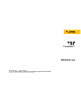
1
Model 787 ProcessMeter Calibration Manual May 1998 Rev. 2, 4/13 © 1998-2013 Fluke Corporation. All rights reserved. Specifications are subject to change without notification. All product names are trademarks of their respective companies. Table of Contents Title Page Introduction........................................................................................................ 1 Read First -- Safety Information ........................................................................ 2 787 Calibration Module ................................................................................. 2 Warnings and Cautions.................................................................................. 2 International Symbols ........................................................................................ 4 Required Equipment .......................................................................................... 4 Specifications ..................................................................................................... 5 DC Volts ........................................................................................................ 5 DC Millivolts ................................................................................................. 6 AC Volts ........................................................................................................ 6 AC Current .................................................................................................... 6 DC Current .................................................................................................... 6 Ohms.............................................................................................................. 7 Frequency Counter Accuracy ........................................................................ 7 Frequency Counter Sensitivity ...................................................................... 7 Diode Test and Continuity Test ..................................................................... 7 DC Current Output ........................................................................................ 8 General Specifications ................................................................................... 8 Basic Maintenance ............................................................................................. 8 Cleaning the 787 ProcessMeter and the 787 Calibration Module ................. 8 Replacing the Battery .................................................................................... 9 Checking and Replacing Fuses ...................................................................... 10 Verification Tests ............................................................................................... 11 Computer-Automated Verification Test Procedures ..................................... 12 Preparing to Perform the Verifications Tests ................................................ 12 Loop Power Test............................................................................................ 14 Current Sourcing Test.................................................................................... 15 Current Measurement Test ............................................................................ 16 Checking the Diode Test Function ................................................................ 17 Checking the Continuity Test Function ......................................................... 19 Resistance Measurement Test........................................................................ 20 DC Millivolts Measurement Test .................................................................. 22 DC Volts Measurement Tests ........................................................................ 23 AC Volts Measurement Test ......................................................................... 23 Frequency Measurement Test ........................................................................ 25 Calibration ......................................................................................................... 26 Preparing for Calibration ............................................................................... 26 Installing the 787 Calibration Module ........................................................... 27 Using the MET/CAL Calibration Software ................................................... 30 Replaceable Parts ............................................................................................... 30 i Model 787 Calibration Manual ii List of Tables Table 1. 2. 3. 4. 5. 6. 7. 8. 9. 10. 11. 12. Title Page International Symbols ............................................................................................ Required Equipment and Software ........................................................................ Current Sourcing Test ............................................................................................ DC mA Test ........................................................................................................... DC Amp Test ......................................................................................................... AC Amp Test ......................................................................................................... Resistance Measurement Test Using a 5500A or 5520A Calibrator ...................... DC mV Test ........................................................................................................... DC Volts Test ......................................................................................................... AC Volts Test ......................................................................................................... Frequency Measurement Test ................................................................................ Replacement Parts .................................................................................................. iii 4 5 15 16 16 16 21 22 23 24 25 30 Model 787 Calibration Manual iv List of Figures Figure 1. 2. 3. 4. 5. 6. 7. 8. 9. 10. 11. 12. 13. 14. Title Replacing the Battery ............................................................................................. Replacing a Fuse .................................................................................................... Verifying Loop Power............................................................................................ Current Sourcing Connections Using the HP 3458A ............................................. Current Measurement Test Connections ................................................................ Diode Test Connections ......................................................................................... Continuity Test Connections .................................................................................. Resistance Measurement Test Connections ........................................................... DC mV Measurement Test Connections ................................................................ AC/DC Voltage Measurement Test Connections................................................... Frequency Measurement Test Connections ........................................................... Calibration Connections for the 787 ProcessMeter ................................................ Connecting the 787 Calibration Module to the UUT ............................................. Replacement Parts .................................................................................................. v Page 9 11 14 15 17 18 19 20 22 24 25 28 29 31 Model 787 Calibration Manual vi Calibration Manual Introduction Warning The information provided in this manual is for the use of qualified personnel only. Do not perform the verification tests or calibration procedures described in this manual unless you are qualified to do so. Caution The 787 ProcessMeter contains parts that can be damaged by static discharge. No procedure in this document requires the case to be opened. If you do so, follow the standard practices for handling static sensitive devices. The Calibration Manual for the 787 ProcessMeter (hereafter, also referred to as “the ProcessMeter” or “the UUT”) provides the following information: • Precautions and Safety information • Specifications • Basic maintenance (cleaning, replacing the battery and fuses) • Verification test procedures • Calibration and calibration adjustment procedures • Accessories and replaceable parts For complete operating instructions, refer to the 787 ProcessMeter Users Manual (on the CD-ROM provided). To contact Fluke, call one of the following telephone numbers: • Technical Support USA: 1-800-44-FLUKE (1-800-443-5853) • Calibration/Repair USA: 1-888-99-FLUKE (1-888-993-5853) • Canada: 1-800-36-FLUKE (1-800-363-5853) • Europe: +31 402-675-200 • Japan: +81-3-6714-3114 • Singapore: +65-6799-5566 • Anywhere in the world: +1-425-446-5500 Or, visit Fluke's website at www.fluke.com. To register your product, visit http://register.fluke.com. To view, print, or download the latest manual supplement, visit http://us.fluke.com/usen/support/manuals. 1 Model 787 Calibration Manual Read First -- Safety Information 787 Calibration Module The calibration procedure for the 787 ProcessMeter requires the use of the 787 Calibration Module (hereafter, also referred to as the “Calibration Module”), which is designed for this purpose. Note It is critical that you be aware of the rating differences between the 787 ProcessMeter and the 787 Calibration Module. • The 787 ProcessMeter complies with IEC 1010-1, ANSI/ISA S82.011994, and CAN/CSA C22.2 No. 1010.1-92, and has received UL and TÜV certification. It is rated 1000 V Overvoltage Category III. • The 787 Calibration Module complies with IEC 1010-1, ANSI/ISA S82.01-1994, and CAN/CSA C22.2 No. 1010.1-92. It is rated 1000 V Overvoltage Category I. The 787 Calibration Module is not rated for the Overvoltage Category III environment. DO NOT USE the 787 Calibration Module during regular operation of the 787 ProcessMeter. DO NOT LEAVE the 787 Calibration Module attached to the 787 ProcessMeter during regular operation of the 787 ProcessMeter. Use the 787 ProcessMeter and the 787 Calibration Module only as described in the 787 ProcessMeter Users Manual and the 787 Calibration Manual, respectively. Otherwise, the protection designed into the ProcessMeter and Calibration Module may be impaired. Warnings and Cautions A Warning identifies conditions and procedures that are dangerous to the user. A Caution identifies conditions and procedures that can cause damage to the Product or the equipment under test. Warnings To avoid possible electric shock or personal injury: • DO NOT USE the Calibration Module during regular operation of the ProcessMeter. • DO NOT LEAVE the Calibration Module attached to the ProcessMeter during regular operation of the ProcessMeter. • Use only the battery eliminator supplied with the Calibration Module as an external power supply, see Table 2. A generic battery eliminator might pose a safety hazard. • DO NOT use the ProcessMeter or the Calibration Module if either one looks damaged. • Examine the ProcessMeter and Calibration Module before use. Look for cracks in the case, missing plastic, or damaged insulation around the connectors. (Continued on next page) 2 Calibration Manual Read First -- Safety Information Warnings (Continued) • Inspect the test leads for damaged insulation or exposed metal. Check for test lead continuity. Replace damaged test leads as necessary. • Do not use the ProcessMeter or the Calibration Module if either operates abnormally. Protection may be impaired. When in doubt, have the instruments serviced. • Do not apply more than the rated voltage, as marked on the ProcessMeter and the Calibration Module, between terminals or between any terminal and earth ground. • When using probes, keep fingers behind the finger guards on the probes. • Use caution when working above 30 V ac rms, 42 V ac peak, or 60 V dc. Such voltages pose a shock hazard. • Connect the common lead (COM) before connecting the live test lead. When disconnecting test leads, disconnect the live test lead first. • Remove test leads from the ProcessMeter before opening the battery door. • Do not operate the ProcessMeter or Calibration Module around explosive gas, vapor or dust. • During normal operation, use only a single properly installed 9 V battery to power the ProcessMeter. • Make sure the battery door is closed and latched before you operate the ProcessMeter. • During Calibration, use only specified calibration equipment listed in Table 2. There are no substitutes for the battery eliminator, Calibration Module, and Calibration Software. • During Calibration, properly connect the Calibration Module to the ProcessMeter. • When servicing the ProcessMeter or the Calibration Module, use only specified replacement parts. • Before measuring current, check the ProcessMeter’s fuses, see “Testing the Fuses” in the 787 Users Manual. • To avoid false readings, which can lead to possible electric shock or personal injury, replace the battery as soon as the low battery indicator () appears. Caution To avoid possible damage to the ProcessMeter or to the test instruments: • Disconnect the power and discharge all high voltage capacitors before testing resistance, diode, or continuity. • Use the proper terminals, rotary switch setting, and range for the measurement or sourcing application. 3 Model 787 Calibration Manual International Symbols International symbols used on the ProcessMeter and in this calibration manual are explained in Table 1. Table 1. International Symbols Symbol Meaning Symbol Meaning Risk of Danger. Important information. See Manual. Earth ground AC (Alternating Current) Conforms to European Union directives DC (Direct Current) Conforms to relevant North American Safety Standards. Alternating or direct current Battery Inspected and licensed by TÜV Product Services Hazardous voltage. Meets Underwriters’ Laboratories safety requirements Conforms to relevant Australian EMC requirements Fuse Double Insulation Conforms to CAN/CSA-C22.2 No 61010-1, second edition, including Amendment 1. Conforms to relevant South Korean EMC Standards. CAT II Measurement Category II is applicable to test and measuring circuits connected directly to utilization points (socket outlets and similar points) of the low-voltage MAINS installation. CAT III Measurement Category III is applicable to test and measuring circuits connected to the distribution part of the building’s low-voltage MAINS installation. CAT IV Measurement Category IV is applicable to test and measuring circuits connected at the source of the building’s low-voltage MAINS installation. This product complies with the WEEE Directive (2002/96/EC) marking requirements. The affixed label indicates that you must not discard this electrical/electronic product in domestic household waste. Product Category: With reference to the equipment types in the WEEE Directive Annex I, this product is classed as category 9 "Monitoring and Control Instrumentation" product. Do not dispose of this product as unsorted municipal waste. Go to Fluke’s website for recycling information. Required Equipment Equipment and software required to perform the procedures in this manual are identified in Table 2. If the recommended equipment model is not available, in some cases other equipment can be substituted as long as it meets the specifications indicated. Warning To avoid safety hazards and equipment damage during the calibration procedure, use the specified calibration equipment listed in Table 2. Using unspecified equipment can jeopardize the verification test and pose safety hazards. 4 Calibration Manual Specifications Note Unless otherwise indicated, all connection diagrams for the verification tests in this manual showing a calibrator or digital multimeter use a Fluke 5500A calibrator or HP 3458A. If you are using a different calibrator or DMM make the connections appropriate for your instrument. Table 2. Required Equipment and Software Equipment Minimum Specifications Recommended Model Calibration Source No Substitute Fluke Model 5500A, 5520A Digital Multimeter No Substitute Fluke 8508A Test Leads, low leakage, RG-58/U type Leakage resistance > than 1.0 x 13 10 Ω at 45 °C and 75 % relative humidity Fluke 5440A-7002 Low Thermal Test Leads Calibration Module w/Battery Eliminator No Substitute. A generic battery eliminator might pose a safety hazard. Includes Cal Module, Battery Eliminator, and Calibration Manual. Fluke-787CAL 120 (USA/Canada) Fluke-787CAL 230 (Europe) Fluke-787CAL 240 (UK) Fluke-787CAL 240AN (Australia) Fluke-787CAL 100 (Japan) Battery Eliminator, Input: 120-240 V AC; Output: 12 V DC/ 300 mA. No Substitute. Only use a BE860 battery eliminator. Fluke BE860 120 (in USA/Can) Fluke BE860 230 (Europe) Fluke BE860 240 (UK) Fluke BE860 240AN (Aus) Null Modem Cable 9-pin to 9-pin Fluke RS 43 Personal Computer Windows 95 or later (Refer to MET/CAL manual set), 64 MB RAM, 500 MB on disk, VGA monitor. Pentium 133 MHz, IBM-compatible Calibration Software No Substitute Fluke MET/CAL Calibration Software Specifications The 787 ProcessMeter’s performance and accuracy are specified for one year after calibration, at operating temperatures of +18 °C to +28 °C (64 °F to 82 °F), in relative humidity to 90 %, after the ProcessMeter has been warmed up for 5 minutes. Note A “count” is the amount by which the least significant digit can vary. DC Volts Range (V dc) Resolution Accuracy, ±(% of Reading + Counts) 4.000 0.001 V 0.1 % + 1 40.00 0.01 V 0.1 % + 1 400.0 0.1 V 0.1 % + 1 1000 1V 0.1 % + 1 Input impedance: 10 MΩ (nominal), < 100 pF Normal mode rejection ratio: >60 dB at 50 Hz or 60 Hz Common mode rejection ratio: >120 dB at dc, 50 Hz, or 60 Hz Overvoltage protection: 1000 V 5 Model 787 Calibration Manual DC Millivolts Range (mV dc) Resolution 400.0 0. 1 mV Accuracy (% of Reading + Counts) 0.1 % + 1 Input impedance: 10 MΩ (nominal), < 100 pF Normal mode rejection ratio: >60 dB at 50 Hz or 60 Hz Common mode rejection ratio: >120 dB at dc, 50 Hz, or 60 Hz Overvoltage protection: 1000 V AC Volts Range (ac) 1 Accuracy ± ( % of Reading + Counts) Resolution 50 Hz to 60 Hz 45 Hz to 200 Hz 200 Hz to 500 Hz 400.0 mV 0.1 mV 0.7 % + 4 1.2 % + 4 7.0 % + 4 4.000 V 0.001 V 0.7 % + 2 1.2 % + 4 7.0 % + 4 40.00 V 0.01 V 0.7 % + 2 1.2 % + 4 7.0 % + 4 400.0 V 0.1 V 0.7 % + 2 1.2 % + 4 7.0 % + 4 1000 V 1V 0.7 % + 2 1.2 % + 4 7.0 % + 4 1. Specifications are valid from 5 % to 100 % of amplitude range. AC conversion: true rms Maximum crest factor: 3 For non-sinusoidal waveforms, add ±(2 % reading + 2 % f.s.) typical. Input impedance: 10 MΩ (nominal), < 100 pF, ac-coupled. Common mode rejection ratio: >60 dB at dc, 50 Hz, or 60 Hz. AC Current Range 45 Hz to 2 kHz 1.000 A 1 Resolution Accuracy ± (% of Reading + Counts) Typical Burden Voltage 0.001 A 1% + 2 1.5 V/A 1. Specifications are valid from 5 % to 100 % of amplitude range. AC conversion: true rms Maximum crest factor: 3 For non-sinusoidal waveforms, add ± (2 % reading + 2 % f.s.) typical. Input impedance: 10 MΩ (nominal), < 100 pF, ac-coupled. Common mode rejection ratio: >60 dB at dc, 50 Hz, or 60 Hz. DC Current Range 30.000 mA 1.000 A 2 Resolution 1 Accuracy ± (% of Reading + Counts) Typical Burden Voltage 0.001 mA 0.05 % + 2 14 mV/mA 0.001 A 0.2 % + 2 1.5 V/A 1 Specifications are valid from 5 % to 100 % of amplitude range. AC conversion: true rms Maximum crest factor: 3 For non-sinusoidal waveforms, add ± (2 % reading + 2 % f.s.) typical. Input impedance: 10 MΩ (nominal), < 100 pF, ac-coupled. Common mode rejection ratio: >60 dB at dc, 50 Hz, or 60 Hz. 2 400 mA continuous, 1A 30 seconds maximum on, 5 minutes off. Overload protection: 440 mA, 1000V fast-blow fuse. 6 Calibration Manual Specifications Ohms Accuracy ± (% of Reading + Counts) Range Resolution Measurement Current 400.0 Ω 0. 1 Ω 220 μA 0.2 % + 2 4.000 kΩ 0.001 kΩ 59 μA 0.2 % + 1 40.00 kΩ 0.01 kΩ 5.9 μA 0.2 % + 1 400.0 kΩ 0.1 kΩ 590 nA 0.2 % + 1 4.000 MΩ 0.001 MΩ 220 nA 0.35 % + 3 40.00 MΩ 0.01 MΩ 22 nA 2.5 % + 3 Overload protection: 1000 V Open circuit voltage: <3.9 V Frequency Counter Accuracy Range Accuracy ± (% of Reading + Counts) Resolution 199.99 Hz 0.01 Hz 0.005 % + 1 1999.9 Hz 0.1 Hz 0.005 % + 1 19.999 kHz 0.001 kHz 0.005 % + 1 Display updates 3 times/second at >10 Hz Frequency Counter Sensitivity Input Range Minimum Sensitivity (rms Sinewave) 0.5 Hz to 20 kHz* 1V 0.1 V 4V 1V 40 V 3V 400 V 30 V 1000 V 300 V * Usable 0.5 Hz to 20 kHz with reduced sensitivity Diode Test and Continuity Test Diode test indication Display voltage drop: 0.2 mA nominal test current at 0.6 V. 2.4 V full scale, accuracy ±( 2 % + 1 count) Continuity test indication continuous audible tone for test resistance <100 Ω Open circuit voltage <3.9 V Short circuit current 1.2 mA typical Overload protection 1000 V rms 7 Model 787 Calibration Manual DC Current Output Source mode Span: 0 mA or 4 mA to 20 mA, with overrange to 24 mA Accuracy: 0.05 % of span Compliance voltage: 12 V with battery voltage >8.5 V Simulate Mode Span: 0 mA or 4 mA to 20 mA, with overrange to 24 mA Accuracy: 0.05 % of span Loop voltage: 24 V nominal, 30 V maximum, 15 V minimum Compliance voltage: 21 V for 24 V supply Burden voltage: <3 V General Specifications Maximum voltage applied between any jack and earth ground ................................... 1000 V Storage temperature ............................................. -40 °C to 60 °C Operating temperature ......................................... -20 °C to 55 °C Operating altitude ................................................. 2000 meters maximum Temperature coefficient ....................................... 0.05 x specified accuracy per °C for temperatures <18 °C or >28 °C Relative humidity .................................................. 95 % up to 30 °C, 75 % up to 40 °C, 45 % up to 50 °C, and 35 % up to 55 °C Vibration ................................................................ Random Mil-prf-28800f, 10 Hz to 500 Hz Shock ..................................................................... 1 meter drop test Power requirements ............................................. Single 9V battery (ANSI/NEDA 1604A or IEC 6LR61) Size ......................................................................... 32 mm H x 87 mm W x 187 mm L (1.25 in H x 3.41 in W x 7.35 in L) With holster ..................................................... 52 mm H x 98 mm W x 201 mm L (2.06 in H x 3.86 in W x 7.93 in L) Weight .................................................................... 369 g (13 oz) With holster ..................................................... 638 g (22.5 oz) Safety ..................................................................... IEC 61010-1, 1000 V CAT III, Pollution Degree 2 Electromagnetic Environment ............................. IEC 61326-1, Portable Electromagnetic Compatibility ............................ Accuracy for all ProcessMeter functions is not specified in RF field >3V/m Applies to use in Korea only ........................... Class A Equipment (Industrial Broadcasting & Communication [1] Equipment [1] This product meets requirements for industrial (Class A) electromagnetic wave equipment and the seller or user should take notice of it. This equipment is intended for use in business environments and not to be used in homes. Basic Maintenance Cleaning the 787 ProcessMeter and the 787 Calibration Module Warning To avoid electrical shock or damage, never allow water inside the case of the ProcessMeter or the 787 Calibration Module. If the ProcessMeter or the 787 Calibration Module requires cleaning, wipe it down with a cloth that is lightly dampened with water or a mild detergent. Do not use aromatic hydrocarbons, chlorinated solvents, or methanol-based fluids when wiping down the ProcessMeter or the 787 Calibration Module. To avoid damaging the case, never apply solvents to the case of the ProcessMeter or the 787 Calibration Module. 8 Calibration Manual Basic Maintenance Replacing the Battery Warning To avoid electrical shock, remove test leads from the ProcessMeter before opening the battery door. Close and latch the battery door before using the ProcessMeter. To avoid false readings, which can lead to possible electric shock or personal injury, replace the battery as soon as the battery low indicator () appears. The ProcessMeter is powered by a 9 V alkaline battery (ANSI/NEDA 1604A or IEC 6LR61). To replace the battery, refer to Figure 1 and do the following: 1. Turn the rotary switch to OFF, remove the test leads from the terminals, and hold the ProcessMeter face down. 2. Using a flat-blade screwdriver, turn the battery door screws 1/4-turn counterclockwise and remove the battery door by. 3. Remove the battery and replace it with a new one. 4. Replace the battery door and secure it by turning the screws 1/4-turn clockwise. LT013F.EPS Figure 1. Replacing the Battery 9 Model 787 Calibration Manual Checking and Replacing Fuses Warning To avoid electric shock or personal injury, remove the test leads and any input signals before replacing a fuse. Make sure that the battery door and case are closed and secured before operating the ProcessMeter. To avoid injury or damage to the ProcessMeter, use ONLY specified replacement fuses with the amperage, voltage, interrupt and speed ratings shown in Table 13. Both current input terminals are fused with a separate 440 mA fuse. To determine if a fuse is blown: 1. Turn the rotary switch to mA A L. 2. Plug the black test lead into COM, and the red test lead into A. 3. Using an ohmmeter, check the resistance between the ProcessMeter test leads. If the resistance is about 1Ω, the fuse is good. An open means the fuse is blown. 4. Move red test lead to mA. 5. Using an ohmmeter, check the resistance between the ProcessMeter test leads. If the resistance is about 14 Ω, the fuse is good. An open means the fuse is blown. To replace a fuse, refer to Figure 2 and do the following: 1. Turn the rotary switch to OFF, remove the test leads from the terminals, and hold the ProcessMeter face down. 2. Remove the battery door by using a flat-blade screwdriver to turn the battery door screws 1/4-turn counterclockwise. 3. Remove the three Hexalobular (star) screws from the case bottom and turn the case over. 4. Gently lift the input terminal-end of the case top to separate the two halves of the case. 5. Remove the fuse by gently prying one end loose, then sliding the fuse out of its bracket. 6. Replace the fuse only with a 440 mA 1000 V fast-blow fuse. (Fluke PN 943121.) Both fuses are the same type. 7. Verify that the rotary switch and the circuit board switch are in the OFF position. 8. Place the case top on the case bottom, ensuring that the gasket is properly seated and the case halves snap together above the LCD end. (See Figure 2.) 9. Reinsert the three case bottom screws and the battery door. 10 Calibration Manual Verification Tests F1 F2 1 LT014F.EPS Figure 2. Replacing a Fuse Verification Tests Warning Some of the verification tests involve the use of high voltages and should be performed by qualified personnel only. To avoid electrical shock, always place the calibrator in the Standby (STBY) mode between tests and before handling the test connections or test cables. Verification tests confirm the complete operability of the 787 ProcessMeter and check the accuracy of each ProcessMeter function against the ProcessMeter’s specifications. If the ProcessMeter fails any verification test, it needs calibration adjustment or repair. The ProcessMeter’s performance and accuracy are specified for one year after calibration at operating temperatures of +18 °C to +28 °C (64 °F to 82 °F), in relative humidity to 90 %. The specifications assume the ProcessMeter has been warmed up for 5 minutes before use. To perform the verification tests, it is not necessary to open the case; no adjustments are necessary. Merely make the required connections, source the designated values, and determine if the reading on the ProcessMeter or the multimeter falls within the acceptable range indicated. These verification test procedures assume that the person performing the tests has read the 787 Users Manual, knows how to select functions and ranges on the ProcessMeter, and knows how to operate the required equipment. 11 Model 787 Calibration Manual Note Verification tests for the 787 ProcessMeter can be performed manually, or they can be computer-automated (using Fluke’s MET/CAL Calibration Software). This document provides the procedures necessary to perform the verification test manually. Computer-Automated Verification Test Procedures Computer-automated verification test procedures for the 787 ProcessMeter are available at the Fluke Calibration website, www.flukecal.com. These procedures require Fluke’s MET/CAL Calibration Software, a 787 Calibration Module, a Fluke 5500A or 5520A Calibrator, and a Fluke 8508A Reference Multimeter. Refer to the MET/CAL manual set for more information. The procedures are: • Fluke 787: (1 year) CAL VER /5500, 3458 • Fluke 787: (1 year) CAL VER /5520, 34401 • Fluke 787: (1 year) CAL VER /5520, 3458 • Fluke 787: (1 year) CAL VER RS-232 /5500, 3458 • Fluke 787: (1 year) CAL VER RS-232 /5520, 34401 • Fluke 787: (1 year) CAL VER RS-232 /5520, 3458 • Fluke 787: CAL ADJ RS-232 /5500, 3458 • Fluke 787: CAL ADJ RS-232 /5520, 3458 Refer to the MET/CAL manual set for more information. Preparing to Perform the Verifications Tests Warning To avoid possible electric shock or personal injury: 12 • DO NOT use the ProcessMeter or the 787 Calibration Module if either looks damaged. • Before proceeding with the verification tests, inspect the ProcessMeter and the Calibration Module for damage, especially around the input terminals. • Look for cracks, missing plastic, or damaged insulation. If damage is detected, do not continue; contact Fluke to arrange to have the ProcessMeter or Calibration Module serviced. • Make sure that the battery door on the ProcessMeter is closed and latched before using the ProcessMeter. • Inspect the test leads and test connections for damaged insulation or exposed metal. • Check the test leads for continuity. Replace damaged test leads as necessary. Calibration Manual Verification Tests • Do not use the ProcessMeter or the Calibration Module if either appears to operate abnormally. Protection designed into the ProcessMeter and Calibration Module might be impaired. If in doubt have the ProcessMeter or Calibration Module serviced. • To avoid electrical shock, always place the calibrator in the Standby (STBY) mode between tests and before handling the test connections or test cables. • Some of the verification tests involve the use of high voltages and should be performed by qualified personnel only. Note These verification tests assume that the person performing them knows how to use the 787 ProcessMeter and the required equipment. Do not attempt to perform these tests unless you are qualified to do so. Throughout the verification tests, “UUT” (unit under test) refers to the 787 ProcessMeter; the word “multimeter” is reserved for the digital multimeter identified in the required equipment listed in Table 2. Unless otherwise indicated, all connection diagrams for the verification tests in this manual showing a calibrator or digital multimeter use a Fluke 5500A calibrator or HP 3458A. If you are using a different calibrator or DMM make the connections appropriate for your instrument. To prepare the UUT for the verification tests, do the following: 1. Make sure that you have the required equipment available. (See Table 2.) 2. Make sure that both fuses in the UUT are intact. See “Checking and Replacing Fuses” earlier in this manual. 3. Make sure the UUT has a fresh battery. See “Replacing the Battery” earlier in this manual. 4. Warm up the calibrator and multimeter as required by their specifications. 5. Remove all input cables from the front of the UUT. 6. Make sure that the UUT is in a stable ambient temperature between 18 °C and 28 °C (64.4 °F and 82.4 °F) and that it has been warmed up for 5 minutes. Warning To avoid possible electrical shock or personal injury: • Some of the following tests involve the use of high voltages and should be performed by qualified personnel only. • To avoid electrical shock always place the calibrator in the Standby (STBY) mode between tests and before handling the test connections. 13 Model 787 Calibration Manual Loop Power Test 1. Make a short circuit connection between the SOURCE + (A) and − (mA) terminals on the UUT. 2. Connect the voltage input terminals of the multimeter to the SOURCE + and COM terminals on the UUT as shown in Figure 3. 3. Put the multimeter in the dc volts () autorange function. 4. Put the UUT rotary switch in the OUTPUT m position. 5. Use the % STEP key to apply 20 mA from the UUT. The multimeter display should read at least 12 V. If the voltage displayed is less than 12 V, either the battery in the UUT is weak or the current source power supply in the UUT is faulty. UUT HP 3458A DC Volts Autorange Function LT006F.EPS Figure 3. Verifying Loop Power 14 Calibration Manual Verification Tests Current Sourcing Test 1. Put the calibrator in Standby (STBY) mode. 2. Connect the SOURCE + (A) and − (mA) terminals on the UUT to the current terminals on the multimeter as shown in Figure 4. 3. Put the multimeter in the dc mA function and manually select 100 mA range. (Do not allow the multimeter to autorange.) 4. Put the UUT rotary switch in the OUTPUT m position. 5. Use the % STEP and COARSE keys on the UUT to apply the values shown in Table 3 and compare the readings on the multimeter to the acceptable readings shown. Table 3. Current Sourcing Test 787 Range 787 Output Current Minimum Acceptable Multimeter Reading Maximum Acceptable Multimeter Reading No Range Switching 4 mA 3.99 mA 4.01 mA No Range Switching 12 mA 11.99 mA 12.01 mA No Range Switching 20 mA 19.99 mA 20.01 mA UUT HP 3458A DC mA Function 100 mA Range LT001F.EPS Figure 4. Current Sourcing Connections Using the HP 3458A 15 Model 787 Calibration Manual Current Measurement Test 1. Put the calibrator in Standby (STBY) mode. 2. Put the UUT rotary switch in the mA A Lposition. 3. Connect the calibrator to the COM and mA terminals on the UUT as shown in Figure 5. 4. Apply the values from the calibrator shown in Table 4 and compare the readings on the UUT to the acceptable readings shown. 5. Connect the calibrator to the COM and A terminals on the UUT. 6. Apply the values from the calibrator shown in Table 5 and compare the readings on the UUT to the acceptable readings shown. 7. Press the BLUE button on the UUT to toggle to ac amps. 8. Apply the values from the calibrator shown in Table 6 and compare the readings on the UUT to the acceptable readings shown. Table 4. DC mA Test Calibrator DC Current 787 Range Minimum Acceptable Reading Maximum Acceptable Reading No Range Switching 4 mA 3.996 mA 4.004 mA No Range Switching 12 mA 11.992 mA 12.008 mA No Range Switching 20 mA 19.988 mA 20.012 mA Table 5. DC Amp Test Calibrator DC Current 787 Range Minimum Acceptable Reading Maximum Acceptable Reading No Range Switching 0.1 A 0.098 A 0.102 A No Range Switching 0.4 A 0.397 A 0.403 A Table 6. AC Amp Test 787 Range 16 Calibrator AC Current and Frequency Minimum Acceptable Reading Maximum Acceptable Reading No Range Switching 0.1 A @ 60 Hz 0.097 A 0.103 A No Range Switching 0.4 A @ 60 Hz 0.394 A 0.406 A Calibration Manual Verification Tests UUT (BLUE) 5500A LT003F.EPS Figure 5. Current Measurement Test Connections Checking the Diode Test Function 1. Put the calibrator in Standby (STBY) mode. 2. Put the UUT rotary switch in the position. 3. Press the BLUE button to select diode test (). 4. Connect the calibrator to the COM and terminals on the UUT as shown in Figure 6. 5. Apply 2.0 V dc from the calibrator. 6. The UUT should read between 1.959 V and 2.041 V. 7. Put the calibrator in Standby (STBY) mode; then disconnect the calibrator from the UUT. 8. Put the multimeter in the dc mA (autorange) function. 9. Connect the current terminals of the multimeter to the COM and terminals on the UUT. 10. The multimeter should read close to 0.2 mA. (There is no tolerance specification for this current. This test just makes sure that the diode test current source is operating.) 17 Model 787 Calibration Manual UUT (BLUE) 5500A UUT HP 3458A DC mA Autorange Function LT007F.EPS Figure 6. Diode Test Connections 18 Calibration Manual Verification Tests Checking the Continuity Test Function 1. Put the calibrator in Standby (STBY) mode, and put the UUT rotary switch in the position. 2. Connect the calibrator to the COM and terminals on the UUT as shown in Figure 7. 3. Press T (continuity beeper) on the UUT to select the continuity test. 4. Using the calibrator, apply a resistance output of 230 ± 20 Ω. The beeper should stay off. 5. Using the calibrator, apply a resistance output of 120 ± 20 Ω. The beeper should turn on. UUT 5500A LT0008F.EPS Figure 7. Continuity Test Connections 19 Model 787 Calibration Manual Resistance Measurement Test 1. Put the calibrator in Standby (STBY) mode. 2. Put the UUT rotary switch in the position. 3. Connect the Output and Sense leads of the calibrator to the UUT as shown by the solid and dotted lines in Figure 8. 4. Apply the calibrator resistance values in Table 7 in the 787 400 Ω to 40 kΩ range. Compare the readings on the UUT to the acceptable readings shown. 5. Change the connections to the UUT. Using the Fluke 5440A-7002 low thermal leads, connect the calibrator to the UUT as shown by the solid lines in Figure 8. 6. Apply the rest of the calibrator resistance values in Table 7 (400 kΩ range and above). Compare the readings on the UUT to the acceptable readings shown. UUT 5500A LT004F.EPS Figure 8. Resistance Measurement Test Connections 20 Calibration Manual Verification Tests Table 7. Resistance Measurement Test Using a 5500A or 5520A Calibrator 787 Range Calibrator Resistance Calibrator Compensation Mode Minimum Reading Maximum Reading 400 Ω 120 Ω 2-Wire 119.6 Ω 120.4 Ω 400 Ω 300 Ω 2-Wire 299.2 Ω 300.8 Ω 4 kΩ 1.2 kΩ 2-Wire 1.197 kΩ 1.203 kΩ 4 kΩ 3 kΩ 2-Wire 2.993 kΩ 3.007 kΩ 40 kΩ 12 kΩ 2-Wire 11.97 kΩ 12.03 kΩ 40 kΩ 30 kΩ 2-Wire 29.93 kΩ 30.07 kΩ 400 kΩ 120 kΩ OFF 119.7 kΩ 120.3 kΩ 400 kΩ 200 kΩ OFF 199.5 kΩ 200.5 kΩ 400 kΩ 300 kΩ OFF 299.3 kΩ 300.7 kΩ 4 MΩ 1.2 MΩ OFF 1.993 MΩ 1.207 MΩ 4 MΩ 3.0 MΩ OFF 2.986 MΩ 3.014 MΩ 40 MΩ 12 MΩ OFF 11.67 MΩ 12.33 MΩ 40 MΩ 30 MΩ OFF 29.22 MΩ 30.78 MΩ 21 Model 787 Calibration Manual DC Millivolts Measurement Test 1. Put the calibrator in Standby (STBY) mode. 2. Put the UUT rotary switch in the m (dc Millivolts) position. 3. Connect the calibrator to the COM and terminals on the UUT as shown in Figure 9. 4. Apply the values from the calibrator shown in Table 8 and compare the readings on the UUT to the acceptable readings shown. Table 8. DC mV Test 787 Range Calibrator DC Voltage Minimum Reading Maximum Reading No Range Switching 100 mV 99.8 mV 100.2 mV No Range Switching 300 mV 299.6 mV 300.4 mV UUT 5500A LT0005F.EPS Figure 9. DC mV Measurement Test Connections 22 Calibration Manual Verification Tests DC Volts Measurement Tests Warning To avoid possible electrical shock or personal injury: • Some of the verification tests involve the use of high voltages and should be performed by qualified personnel only. • Always place the calibrator in the Standby (STBY) mode between tests and before handling the test connections or test cables. 1. Put the calibrator in Standby (STBY) mode. 2. Put the UUT rotary switch in the (dc volts) position. 3. Connect the calibrator to the COM and terminals on the UUT as shown in Figure 10. 4. Set the UUT to the requested range. 5. Apply the values from the calibrator shown in Table 9 and compare the readings on the UUT to the acceptable readings shown. Table 9. DC Volts Test 787 Range Calibrator DC Voltage Minimum Reading Maximum Reading 4 V dc 1V 0.998 V 1.002 V 4 V dc 3V 2.996 V 3.004 V 40 V dc 10 V 9.98 V 10.02 V 40 V dc 30 V 29.96 V 30.04 V 400 V dc 100 V 99.8 V 100.2 V 400 V dc 300 V 299.6 V 300.4 V 1000 V dc 100 V 99 101 1000 V dc 800 V 798 802 AC Volts Measurement Test Warning To avoid possible electrical shock or personal injury: • Some of the verification tests involve the use of high voltages and should be performed by qualified personnel only. • Always place the calibrator in the Standby (STBY) mode between tests and before handling the test connections or test cables. 1. Put the calibrator in Standby (STBY) mode. 2. Put the UUT rotary switch in the (ac volts) position. 3. Connect the calibrator to the COM and terminals on the UUT as shown in Figure 10. 4. Apply the values from the calibrator shown in Table 10 and compare the readings on the UUT to the acceptable readings shown. 23 Model 787 Calibration Manual UUT (BLUE) 5500A LT0009F.EPS Figure 10. AC/DC Voltage Measurement Test Connections Table 10. AC Volts Test 787 Range 24 Calibrator Voltage and Frequency Minimum Acceptable Reading Maximum Acceptable Reading 400 mV ac 100 mV @ 60 Hz 98.9 mV 101.1 mV 400 mV ac 300 mV @ 60 Hz 297.5 mV 302.5 mV 4 V ac 1 V @ 60 Hz 0.991 V 1.009 V 4 V ac 2 V @ 60 Hz 1.984 V 2.016 V 4 V ac 3 V @ 60 Hz 2.977 V 3.023 V 40 V ac 10 V @ 60 Hz 9.91 V 10.09 V 40 V ac 30 V @ 60 Hz 29.77 V 30.23 V 400 V ac 100 V @ 60 Hz 99.1 V 100.9 V 400 V ac 300 V @ 60 Hz 297.7 V 302.3 V 1000 V ac 100 V @ 60 Hz 97 103 1000 V ac 800 V @ 60 Hz 792 808 Calibration Manual Verification Tests Frequency Measurement Test 1. Put the calibrator in Standby (STBY) mode. 2. Put the UUT rotary switch in the (ac volts) position. 3. Press F to toggle to the frequency measurement function. 4. Connect the calibrator to the COM and terminals on the UUT as shown in Figure 11. 5. Apply the values from the calibrator shown in Table 11 and compare the readings on the UUT to the acceptable readings shown. Table 11. Frequency Measurement Test 787 Range Calibrator Voltage and Frequency Minimum Acceptable Reading Maximum Acceptable Reading 199.99 Hz 5 V @ 100 Hz 99.98 Hz 100.02 Hz 1999.9 Hz 5 V @ 1000 Hz 999.8 Hz 1000.2 Hz 19.999 kHz 5 V @ 10 kHz 9.998 kHz 10.002 kHz UUT 5500A 5500A CALIBRATOR NORMAL SCOPE AUX V, , RTD A, -SENSE, AUX V 200V PK MAX STBY OPR EARTH 7 8 9 4 5 6 1 2 3 +/ 0 • SCOPE PREV MENU BOOST HI 20V RMS MAX 1000V RMS MAX TRIG OUT LO dBm m n W k sec V Hz SETUP RESET ¡C NEW REF CE MEAS TC TRIG OUT MULT DIV ¡F A 1V PK MAX 20V PK MAX p F M TC SHIFT ENTER 20V PK MAX x EDIT FIELD POWER I O LT010F.EPS Figure 11. Frequency Measurement Test Connections 25 Model 787 Calibration Manual Calibration The 787 ProcessMeter is calibrated using a closed-case, automated procedure, that requires Fluke’s MET/CAL Calibration Software and the 787 Calibration Module. Calibrate your ProcessMeter once a year to ensure that it performs according to its specifications. Warning To avoid possible electrical shock or personal injury: • Some of the verification tests involve the use of high voltages and should be performed by qualified personnel only. • Always place the calibrator in the Standby (STBY) mode between tests and before handling the test connections or test cables. Preparing for Calibration Warning To avoid possible electric shock or personal injury: 26 • DO NOT use the ProcessMeter or the Calibration Module if either looks damaged. • Before proceeding with the verification tests, inspect the ProcessMeter and the Calibration Module for damage, especially around the input terminals. • Look for cracks, missing plastic, or damaged insulation. If damage is detected, do not continue; contact Fluke to arrange to have the ProcessMeter or Calibration Module serviced. • Make sure that the battery door on the ProcessMeter is closed and latched before using the ProcessMeter. • Inspect the test leads and test connections for damaged insulation or exposed metal. • Check the test leads for continuity. Replace damaged test leads as necessary. • Do not use the ProcessMeter or the Calibration Module if either appears to operate abnormally. Protection designed into the ProcessMeter and Calibration Module might be impaired. If in doubt have the ProcessMeter or Calibration Module serviced. • To avoid electrical shock, always place the calibrator in the Standby (STBY) mode between tests and before handling the test connections or test cables. • Some of the verification tests involve the use of high voltages and should be performed by qualified personnel only. Calibration Manual Calibration Note The calibration procedures assume that the person performing them knows how to use the 787 ProcessMeter and the required equipment. Do not attempt to calibrate the ProcessMeter unless you are qualified to do so. Throughout the following, “UUT” (unit under test) refers to the 787 ProcessMeter; the word “multimeter” is reserved for the digital multimeter identified in the required equipment listed in Table 2. Calibration should be performed in an RF field <1 V/m such as a laboratory environment. To prepare for calibration, do the following: 1. Make sure that you have the required equipment available (see Table 2) and that the MET/CAL Calibration Software is properly loaded on your PC. 2. Make sure that both fuses in the UUT are intact. See “Checking and Replacing Fuses” earlier in this manual. 3. Connect the Calibrator to the PC using an IEEE-488 cable. 4. Turn on and warm up the calibrator as required by its specifications. 5. Remove all input cables from the front of the UUT. 6. Make sure that the UUT is in an ambient temperature between 18 °C and 28 °C (64.4 °F and 82.4 °F). Installing the 787 Calibration Module During the calibration procedure, the UUT communicates over the battery cable with the 787 Calibration Module (hereafter referred to as the “Calibration Module”) via a singleduplex, RS-232 interface. The Calibration Module contains a circuit that both optically isolates the computer’s communication port from the UUT and converts the RS-232 signals to the appropriate format for communication with the UUT. Warning To avoid possible electrical shock or personal injury: • To maintain safe conditions during calibration, the 787 Calibration Module must be properly attached to the UUT’s battery lead connector, and the battery door on the ProcessMeter must be secured. See Figure 12. • When performing the following procedure, only use the battery eliminator provided with the Calibration Module (see Table 2). A generic battery eliminator might pose a safety hazard. To install the 787 Calibration Module, do the following while referring to Figures 12 and 13 as necessary: 1. Remove all input cables from the front of the UUT and open the battery door on the UUT. 2. Remove the battery from the battery receptacle of the UUT and unplug the battery from the battery cable connector. 27 Model 787 Calibration Manual 3. Plug the battery connector from the UUT into the connector on the battery door of the Calibration Module. 4. Attach the battery door on the Calibration Module cable to the UUT. 5. Connect Calibration Module to the appropriate communication port on the PC, using an RS-232 9-pin, null modem cable. (See Figure 13.) Note The calibration procedure does not support the UUT port on the Fluke 5500A and 5520A calibrators. 6. Connect the battery eliminator to the Calibration Module, and plug the battery eliminator into an AC outlet. 7. Turn the rotary switch on the UUT to the position and warm up the UUT for five minutes. 8. Start MET/CAL and select the calibration procedure that matches the calibrator and multimeter in use. LT015F.EPS Figure 12. Calibration Connections for the 787 ProcessMeter 28 Calibration Manual Calibration 2 1 3 4 Warning Secure Battery Door to UUT. 5 6 Warning Battery Eliminator Cable RS43 Cable 9-Pin Null Modem Cable To PC RS43 Cable 9-Pin Null Modem Cable To Outlet Battery Eliminator Cable Only use the battery eliminator supplied with the calibration module (see Table 2). Warning Battery Door Must Secured to UUT. LT011F.EPS Figure 13. Connecting the 787 Calibration Module to the UUT 29 Model 787 Calibration Manual Using the MET/CAL Calibration Software To calibrate the UUT using the MET/CAL Calibration Software, start MET/CAL and follow the prompts. For each function being calibrated, you will be prompted to set the UUT rotary switch to the correct position, and to make the appropriate connections between the calibrator, other required equipment, and the UUT. Except for positioning the rotary switch and making the proper connections, the calibration process is completely automated. Warning The MET/CAL Calibration Software program automatically puts the Calibrator in Standby (STBY) mode before prompting you to change connections. To ensure your safety, however, always check the Calibrator to make sure that it actually is in the Standby (STBY) before changing connections with the UUT and all other equipment used in calibration. Replaceable Parts When servicing this ProcessMeter, use only the replacement parts specified. Userreplaceable parts are listed in Table 12 and shown in Figure 14. Table 12. Replacement Parts Item Fluke PN or Model no. Quantity BT1 9V battery, ANSI/NEDA 1604A or IEC 6LR61 614487 1 MP103 Holster, Yellow 2074033 1 ! F1, 2 Fuse, 440 mA, 1000V fast-blow 943121 2 MP85 Case top 619962 1 MP86 Case bottom 619939 1 H2, 3, 4 Case screw 832246 3 MP89, 90 Non-skid foot 824466 2 MP8 O-ring for input/output receptacle 831933 1 MP92 Battery door 619947 1 H5, 6 Battery door fasteners 948609 2 S1 Keypad 646932 1 [1] Not shown Test Leads variable 1 (set of 2) Not shown Alligator Clips variable[1] 1 (set of 2) [1] Not shown Industrial test lead set variable Option Not shown Quick Reference Guide 4276679 1 Not shown Users Manual (CD-ROM) 1586721 1 Not shown Calibration Manual 641891 Option [1] 30 Description See www.fluke.com for more information about the test leads and alligator clips available for your region. Calibration Manual Replaceable Parts MP85 Holster MP103 S1 Tilt Stand F2 F1 MP8 MP86 H2, 3, 4 BT1 MP89, 90 CD-ROM (Users Manual) MP92 H5, 6 LT012F.EPS Figure 14. Replacement Parts 31 Model 787 Calibration Manual 32