1
712 English Instruction Sheet
Page 1
®
712
RTD Calibrator
Instruction Sheet
Introduction
Fluke Model 712 RTD Calibrator is a handheld tool for calibrating
RTD (Resistance Temperature Detector) transmitters, including
most pulsed transmitters. It simulates and measures seven
different types of RTDs, in units of °C or °F. It also simulates and
measures resistance in units of ohms. It does not source and
measure simultaneously.
Your calibrator is supplied with a Flex-Stand holster, an
installed 9 V alkaline battery, two sets of test leads, and this
instruction sheet.
If the calibrator is damaged or something is missing, contact the
place of purchase immediately. Contact your Fluke distributor for
information about accessories. To order replacement parts or
spares, see “Replacement Parts.”
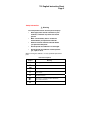
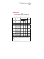
The next table lists the RTD types supported by the calibrator,
with their ranges, resolution, and the allowable excitation current
from an RTD measurement device under test. All RTD types use
ITS-90 curves. Full calibrator specifications are listed at the end
of this instruction sheet.
PN 650280 August 1997, Rev.2, 5/04
1997-2004 Fluke Corporation. All rights reserved. Printed in U.S.A.
All product names are trademarks of their respective companies.
712 English Instruction Sheet
Page 2
Safety Information
W Warning
To avoid possible electric shock or personal injury:
•
Never apply more than 30 V between any two
terminals, or between any terminal and earth
ground.
•
Make sure the battery door is closed and
latched before you operate the calibrator.
•
Remove test leads from the calibrator before
you open the battery door.
•
Do not operate the calibrator if it is damaged.
•
Do not operate the calibrator around explosive
gas, vapor, or dust.
When servicing the calibrator, use only specified replacement
parts.
International Symbols
Symbol
J
Meaning
Earth ground
I
Fuse
M
Battery
W
Refer to this instruction sheet for information about
this feature.
T
Double insulated
$
Conforms to relevant Canadian Standards
Association directives
P
Conforms to European Union directives
712 English Instruction Sheet
Page 3
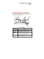
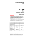
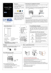
Getting Acquainted with the Calibrator
Press the green O pushbutton to turn the calibrator on and off.
Press the INPUT/OUTPUT pushbutton to select either INPUT
(measuring) or OUTPUT (simulating).
1
3
2
4
8
7
6
5
kg03f.eps
Display Elements
Element
Meaning
A INPUT
Lit when measuring an RTD or resistance
B OUTPUT
Lit when simulating an RTD or resistance
Ci
When simulating an RTD or ohms, the excitation
current from the measuring device under test is too
high. The calibrator output is unspecified.
H
D °C, °F, Ω
When an RTD type is selected, one of these is lit
to show the selected scale.
712 English Instruction Sheet
Page 4
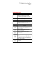
Display Elements (cont.)
Element
Meaning
E 2W, 3W, 4W
When measuring an RTD, one of these is lit to
indicate a two-wire, three-wire, or four-wire
configuration. These annunciators are not used
when simulating an RTD or resistance (output).
F RTD TYPES
The RTD type annunciators (example, Ni 120)
show the selected RTD type.
GB
Lit when the battery is low.
H Numerals
Show the measured or simulated value in degrees
or ohms. When OL appears, the value is out of
range.
Pushbutton Functions
Pushbutton
Function
R
Press to select a different RTD type. When you
select the e type (ohms), displayed units are
ohms, not degrees.
C
Press to toggle temperature scales between
Celsius and Fahrenheit.
o
Press to select input (measure) or output
(simulate) mode.
2W 3W 4W
[
{
]
}
In simulate mode, press to step up or down 50° or
50 Ω.
In measurement mode, press [ or { to select
a two-wire, three-wire, or four-wire RTD input
configuration. You will see the corresponding 2W,
3W, or 4W on the display.
Press to scroll up or down display. Hold down to
scroll faster.
712 English Instruction Sheet
Page 5
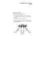
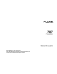
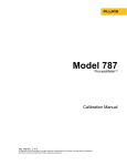
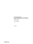
Simulating an RTD
To simulate an RTD, proceed as follows:
1.
Press O to turn on the power.
2.
If the calibrator is in input mode (INPUT on the display),
press INPUT OUTPUT once. Make sure the display shows
OUTPUT.
3.
Press R to select the desired RTD type.
4.
Connect test leads to the terminals of the RTD measuring
device as shown. Use only the two center outputs (labeled
2W 3W 4W OUTPUT).
INPUT
4W
NC
Sense
connection
(if needed)
30V
MAX
30V
MAX
2W 3W 4W
OUTPUT
RTD
measurement
device input
30V
MAX
3W
NC
Sense
connection
(if needed)
kg01f.eps
712 English Instruction Sheet
Page 6
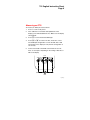
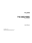
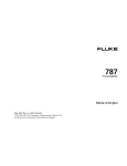
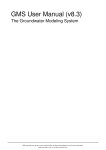
Measuring an RTD
To measure an RTD, proceed as follows:
1.
Press O to turn on the power.
2.
If the calibrator is in simulate mode (OUTPUT on the
display), press INPUT OUTPUT once. Make sure the display
shows INPUT.
3.
Press R to select the desired RTD type.
4.
Press [ or { to select a two-wire, three-wire, or fourwire RTD input configuration. Look for the 2W, 3W, or 4W
annunciator on the display to verify that the configuration is
set correctly.
5.
Connect test leads to the RTD as shown below. Use two,
three, or four inputs, depending on the setting of 2W, 3W, or
4W on the display.
INPUT
4W
NC
30V
MAX
30V
MAX
2W 3W 4W
OUTPUT
4W
30V
MAX
3W
NC
3W
RTD
kg02f.eps
712 English Instruction Sheet
Page 7
Maintenance
For maintenance procedures not described in this sheet, contact
a Fluke Service Center.
In Case of Difficulty
•
Check the battery and test leads. Replace as necessary.
•
Review this sheet to make sure you are using the calibrator
correctly.
If the calibrator needs repair, contact a Fluke Service Center. If
the calibrator is under warranty, see the warranty statement for
terms. If the warranty has lapsed, the calibrator will be repaired
and returned for a fixed fee. Contact a Fluke Service Center for
information and price.
Cleaning
Periodically wipe the case with a damp cloth and detergent; do
not use abrasives or solvents.
Calibration
Calibrate your calibrator once a year to ensure that it performs
according to its specifications. A calibration manual is available
(PN 686540). Call 1-800-526-4731 from the USA and Canada. In
other countries, contact a Fluke Service Center.
712 English Instruction Sheet
Page 8
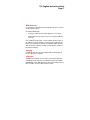
Replacing the Battery
When the B symbol appears on the display, replace the
battery with a 9 V alkaline battery.
it07f.eps
712 English Instruction Sheet
Page 9
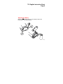
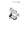
Testing and Replacing the Fuses
WWarning
To avoid personal injury or damage to the
calibrator, use only a 0.125A 250V fast fuse,
Littelfuse 2AG.
Fuse F1 protects the input circuit. Fuse F2 protects the output
circuit. Test and replace the fuses using the following procedure:
1.
Remove the test leads from the calibrator terminals and turn
the calibrator off.
2.
Remove the battery door.
3.
Remove the three Phillips-head screws from the case
bottom and turn the case over.
4.
Gently lift the top cover from the end nearest the input/output
terminals until it unsnaps from the bottom cover.
5.
Gently remove the fuse from its mounting bracket.
6.
Measure the resistance of the fuse. An open or high
resistance suggests that the fuse is blown.
7.
Replace the blown fuse with a 0.125 A 250 V fast fuse,
Littelfuse 2AG.
8.
Fit the top and bottom covers together, engaging the two
snaps. Make sure that the keypad and the input/output
terminal gasket are properly seated.
9.
Reinstall the three screws.
10. Replace the battery door.
712 English Instruction Sheet
Page 10
F1
F2
Snaps
kg08f.eps
712 English Instruction Sheet
Page 11
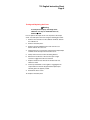
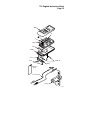
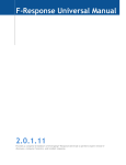
Replacement Parts and Accessories
Replacement Parts
Item
Description
PN or
Model
no.
Qty.
BT1
9V battery, ANSI/NEDA 1604A or
IEC 6LR61
614487
1
CG81Y
Holster, Yellow
CG81Y
1
W F1,F2
Fuse, 125 mA, 250V fast
686527
2
MP85
Case top
620192
1
MP86
Case bottom
620168
1
H2, 3, 4
Case screw
832246
3
MP89, 90
Non-skid foot
824466
2
MP8
O-ring for input/output receptacle
831933
1
MP92
Battery door
609930
1
H5, 6
Battery door fasteners
948609
2
S1
Keypad
687084
1
-
712 Instruction Sheet
650280
1
-
Test lead, red
688051
2
-
Test lead, black
688066
2
-
71X Series Calibration Manual
686540
Option
712 English Instruction Sheet
Page 12
MP85
S1
F2
F1
MP8
BT1
MP86
H2, 3, 4
MP89, 90
H5, 6
MP92
Instruction
Sheet
Test Lead Set
Holster
kg10c.eps
712 English Instruction Sheet
Page 13
Specifications
Specifications are based on a one year calibration cycle and
apply for ambient temperature from +18°C to +28°C unless
stated otherwise.
Note
Specifications on this Instruction Sheet apply to the 712
RTD Calibrators with serial number 7676001 or above.
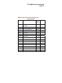
Ohms Specifications
Ohms
Range
Input
Accuracy
Output
Accuracy
4-Wire ±Ω
0.00Ω to
400.00Ω
0.1
400.0Ω to
1500.0Ω
1500.0Ω to
3200.0Ω
±Ω
Allowable
Excitation (mA)
0.15
0.1 to 0.5
0.1
0.5 to 3.0
0.5
0.5
0.05 to 0.8
1
1
0.05 to 0.4
Allowable Excitation is for Output mode only. It shows the allowable
excitation current from an ohmmeter or RTD measurement device
connected to the calibrator.
Excitation current from 712: 0.2 mA.
Maximum input voltage: 30 V
712 English Instruction Sheet
Page 14
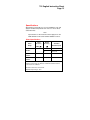
RTD Specifications
Note
Since ohms input and output units are available, you
can use the calibrator for any unsupported RTD type by
selecting the ohms range and making manual
calculations or referring to tables.
Accuracy (°C)
Allowable
Excitation
2-Wire Output
(mA)
&
3-Wire
Input
RTD Type
Range °C (°F)
Ni 120
-80.0 to 260.0
(-112.0 to 500.0)
Pt 100 385
-200.0 to 800.0
(-328.0 to 1472.0)
Pt 200 385
-200.0 to 250.0
(-328.0 to 482.0)
250.0 to 630.0
(482.0 to 1166.0)
Pt 500 385
-200.0 to 500.0
(-328.0 to 932.0)
500.0 to 630.0
(932.0 to 1166.0)
Pt 1000 385 -200.0 to 100.0
(-328.0 to 212.0)
100.0 to 630.0
(212.0 to 1166.0)
Pt 100 392
-200.0 to 630.0
(3926)
(-328.0 to 1166.0)
Pt 100 JIS
-200.0 to 630.0
(3916)
(-328.0 to 1166.0)
4-Wire
0.2
0.3
0.2
0.1 to 3.0
0.33
0.5
0.33
0.1 to 3.0
0.2
0.3
0.2
0.1 to 3.0
0.8
1.6
0.8
0.3
0.6
0.3
0.4
0.9
0.4
0.2
0.4
0.2
0.2
0.5
0.2
0.3
0.5
0.3
0.1 to 3.0
0.3
0.5
0.3
0.1 to 3.0
0.05 to 0.8
0.05 to 0.4
Addresses pulsed transmitters and PLCs with pulses as short as 5 ms.
Allowable Excitation is for Output mode only. It shows the allowable excitation
current from an ohmmeter or RTD measurement device connected to the
calibrator.
Excitation current from 712: 0.2 mA.
Maximum input voltage: 30 V
712 English Instruction Sheet
Page 15
General Specifications
Resolution: RTD: 0.1°C, 0.1°F. Ohms: 0.1Ω
Maximum voltage applied between any terminal and earth
ground or between any two terminals: 30 V
Storage temperature: -20°C to 60°C
Operating temperature: -10°C to 55°C
Operating altitude: 3000 meters maximum
Temperature coefficient: 0.005% of ohms range per °C for
temperature ranges -10°C to 18°C and 28°C to 55°C. Ohms
ranges are 400 Ω, 1.5 kΩ, and 3.2 kΩ.
Relative humidity: 95% up to 30°C, 75% up to 40°C, 45% up to
50°C, and 35% up to 55°C
Vibration: Random 2 g, 5 Hz to 500 Hz
Shock: 1 meter drop test
Safety: Certified as compliant to CAN/CSA C22.2 No.
1010.1:1992. Complies with ANSI/ISA S82.01-1994.
Power requirements: Single 9 V battery (ANSI/NEDA 1604A or
IEC 6LR61)
Size: 32 mm H x 87 mm W x 187 mm L (1.25 in H x 3.41 in W x
7.35 in L);
With holster and Flex-Stand: 52 mm H x 98 mm W x 201 mm L
(2.06 in H x 3.86 in W x 7.93 in L)
Weight: 337 g (11.9 oz);
With holster and Flex-Stand: 587 g (20.7 oz)
712 English Instruction Sheet
Page 16
How to Contact Fluke
To order accessories, receive operating assistance, or get the
location of the nearest Fluke distributor or Service Center, call:
To contact Fluke, call one of the following telephone numbers:
USA: 1-888-99-FLUKE (1-888-993-5853)
Canada: 1-800-36-FLUKE (1-800-363-5853)
Europe: +31 402-675-200
Japan: +81-3-3434-0181
Singapore: +65-738-5655
Anywhere in the world: +1-425-446-5500
Or, visit Fluke's Web site at www.fluke.com.
To register your product, visit register.fluke.com
Address correspondence to:
Fluke Corporation
P.O. Box 9090,
Everett, WA 98206-9090
U.S.A.
Fluke Europe B.V.
P.O. Box 1186,
5602 BD Eindhoven
The Netherlands
LIMITED WARRANTY & LIMITATION OF LIABILITY
This Fluke product will be free from defects in material and workmanship
for three years from the date of purchase. This warranty does not cover
fuses, disposable batteries or damage from accident, neglect, misuse or
abnormal conditions of operation or handling. Resellers are not
authorized to extend any other warranty on Fluke’s behalf. To obtain
service during the warranty period, send your defective calibrator to the
nearest Fluke Authorized Service Center with a description of the
problem.
THIS WARRANTY IS YOUR ONLY REMEDY. NO OTHER
WARRANTIES, SUCH AS FITNESS FOR A PARTICULAR PURPOSE,
ARE EXPRESSED OR IMPLIED. FLUKE IS NOT LIABLE FOR ANY
SPECIAL, INDIRECT, INCIDENTAL OR CONSEQUENTIAL DAMAGES
OR LOSSES, ARISING FROM ANY CAUSE OR THEORY. Since some
states or countries do not allow the exclusion or limitation of an implied
warranty or of incidental or consequential damages, this limitation of
liability may not apply to you.