1
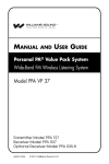
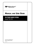
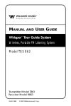
Installation
Guide &
User
Manual
PERSONAL PA® Pro Wide–band System 275
Wireless FM Listening System
Transmitter Model T4
Receiver Model R30
MAN 103 A
®
Williams
Sound
Helping People Hear
PRO WIDE–BAND SYSTEM, MODEL PPA 275
INSTALLATION GUIDE & USER MANUAL
Contents
Page
FAST SET-UP PROCEDURE
4
SYSTEM OVERVIEW
6
CONTROLS AND CONNECTORS
8
DETAILED SET-UP PROCEDURE
4
MOUNTING THE TRANSMITTER
INSTALLING THE ANTENNA
CHOOSING A CHANNEL
CHOOSING AND CONNECTING AN AUDIO SOURCE
CHOOSING AN AUDIO SOURCE FOR THE HEARING IMPAIRED
CONNECTING THE POWER SUPPLY
ADJUSTING THE AUDIO INPUT CONTROL
AUDIO PROCESSOR OPTIONS
16
ASSURING EXCELLENT PERFORMANCE
17
RECEIVER USE INSTRUCTIONS
18
BATTERY INFORMATION
19
RADIO INTERFERENCE TUNING INSTRUCTIONS
20
SUGGESTIONS FOR RECEIVER MANAGEMENT
21
TROUBLESHOOTING GUIDE
22
WARRANTY
25
SYSTEM SPECIFICATIONS
26
Williams
Sound ®
Helping People Hear
3
FAST SETUP PROCEDURE
Step 1
Choose a Location for the Transmitter
It’s usually most convenient to locate the T4 next to the public address equipment. The
location must have the audio feed and 120 VAC power available. Place the transmitter on a
level surface where there are no substantial metal or other electrically conductive objects
between the antenna and the listening area.
After initial adjustments, there should be no need to access the unit.
Step 2
Choose a Location and Install the Antenna
The T4 is equipped with a short flexible antenna (ANT 021). The ANT 021 threads onto a
stud recessed in a hole on the top of the transmitter. Do not use excessive force to tighten the
antenna; it need only be finger tight.
The T4 Transmitter can also be purchased with a coaxial antenna (ANT 005) or Wall Mount
Dipole Antenna (ANT 024).
See Remote Antenna Location Tips on page 11 for more detail.
Step 3
Choose a Channel
Both the T4 Transmitter and R30 Receivers are set to 72.9 MHz at the factory, unless
otherwise specified. However, you may easily set the T4 to any of the 10 available channels
using the FM Channel/FM Power Switch. You may wish to use a different channel if there is
already another hearing assistance system or some other authorized radio service operating
on 72.9 MHz in your area.
Receivers must also be set to the same frequency as the transmitter. See page 22 for receiver
tuning instructions.
Step 4
Choose and Connect an Audio Source
Plug the T4’s audio cable into a Line Out, Record Out, Tape Out or Auxiliary Out jack on
your system amplifier. If these outputs are already in use, a simple Y–cord can be used to
make the connection. Plug the other end of the audio cable into the T4’s Audio Input Jack on
the rear panel. If all line level outputs are in use, the T4’s line out jack on the transmitter’s
rear panel can be used to feed other devices.
IMPORTANT: If you choose to connect to 70 Volt Speaker line, be certain to set the
Audio Config switch correctly. Transmitter damage will occur if you do not.
4
Williams
Sound ®
Helping People Hear
Step 5
Set the Audio Select DIP Switches
Set the Audio Select switch for the type of source you’re using.
If you have used the audio cable provided with the PPA 275, there is no need to change
the factory set configuration.
If you have used a different type of cable, see the T4’s top panel and pages 10 and 13 for the
appropriate switch configurations and plug wiring diagrams. See page 15 for Compress vs.
Limit adjustments.
Step 6
Connect the Power Supply
Plug the T4’s transformer into a standard 120 VAC outlet and connect the attached cable to
the transmitter. The cable connector has a retaining catch which must be installed toward the
top of the transmitter as illustrated on the T4’s back panel. The T4 will not operate if you
install the cable upside down, though no damage will result.
Neither the T4, nor its power supply, are equipped with a power switch. Because there is no
“wear out” mechanism and power consumption is minimal, continuous operation is not a
problem.
Step 7
Adjust the Audio Input Control
Play a compact disc or other good audio source through the complete sound system at a level
that is typical of normal operation.
Adjust the Audio Input control so that the Level Indicator 0 dB LED generally lights and the
+6 dB LED lights occasionally.
Step 8
Listen with the Receiver
Install the batteries, plug in the earphone, turn on the receiver and walk around the listening
area. The signal should be clear and quite loud when the volume is turned up. See page 17
for performance checks.
For more detailed installation procedures, see page 11. For more detailed system description,
see page 8.
Williams
Sound ®
Helping People Hear
5
SYSTEM OVERVIEW
The PPA 275 is a Wide-band FM Listening System which operates in the 72–76 MHz
frequency band.
Developed for hearing assistance in places of public access, the PPA 275 is designed for
those who need help overcoming background noise, reverberation, or distance from the
sound source. It includes a complete audio processor optimized for the needs of hearing
impaired persons and is easily integrated with your existing sound system. The PPA 275 can
also be used with a microphone as a stand-alone system.
Your PPA 275 has two principle parts: the T4 Transmitter and the R30 Receivers. Much like
a miniature radio station, the transmitter and microphone pick up the sounds you want to hear
and broadcast them over an FM radio signal. The receivers pick up the broadcast up to 500
feet away.
Listeners may sit anywhere and can make the audio signal as loud as they wish without
causing PA system feedback or disturbing others.
To avoid difficulties, read through this manual as you begin to use the system. Then save it
for questions that arise as you continue to use your PPA system.
If you have any problems with this Williams Sound product, don’t hesitate to call us toll-free
at 1-800-843-3544.
FIGURE 1: OVERALL SYSTEM DIAGRAM
Loudspeakers
Microphones
Line-Level
Output
PPA T4 Professional FM Auditory Assistance Transmitter
Phones
Audio Adjust
Sound System Amplifier
Williams Sound
Frequency Synthesized, Channel-Selectable
Line-Level
Input
Power
Audio Level
-12dB -6dB
Decrease
0dB +6dB
RF Carrier
Increase
Lo
Ok
Ok
Too Hi
T4 Transmitter
R30 Receivers
w/Earphones
6
Williams
Sound ®
Helping People Hear
FIGURE 2: T4 TRANSMITTER CONTROLS & FEATURES
Audio Level Indicators
Phones Jack
Four-LED array shows audio level in 6 dB steps. Optimum level
is reached when the amber 0 light usually blinks and the red +6
light blinks occasionally.
1/4" jack, 220 Ω source impedance. Drives mono or stereo
headphone. Monitors exactly what is being transmitted.
PPA T4 Professional FM Auditory Assistance Transmitter
Williams Sound
Frequency Synthesized, Channel-Selectable
Phones
Audio Adjust
Audio Level
Power
-12dB -6dB
Decrease
0dB +6dB
RF Carrier
Increase
Lo
Ok
Ok
Too Hi
Power On Indicator
Audio Level Control
RF Indicator
Green LED
Rotary pot, screwdriver adjust,
used with audio level indicator lights
Green LED indicates transmitter RF is on
Audio Select Switches
Line Out
DIP switch, sets input characteristics, audio
processing mode, and input filter cutoff
frequency. (See top panel chart or Figure 3)
Line level output of the fully
processed, as transmitted, audio.
Can be used for monitoring,
recording, or as a feed for other
equipment.
Audio Input
Model PPA T4 Auditory Assistance FM Transmitter
Williams Sound Corp., Minneapolis, MN USA
(XLR) Bal. Mic
Bal./Unbal line or 70V
Audio Select
Line Out
(TRS) Bal./Unbal .
Line or 70V
1 2 3 4 5 6 7 8
To configure, see chart on top.
FM Channel,
Power
Antenna
Power: 24 VAC,
50-60 Hz, 10VA
1 2 3 4 5 6 7 8
See chart on top.
Plug
75 Ohms
Balanced/Unbalanced Audio Input
FM Channel/FM Power Switches
Combination 3-pin female XLR/1/4" stereo jack, accepts
balanced or unbalanced microphone and line level inputs,
25 V or 70 V audio input
DIP switch for setting channel frequency and
RF output power level. See chart on top of
unit for switch configurations (Fig. 3, page 8).
Power
Connection
3-pin, Molex
connector for TFP
016 power supply
IMPORTANT: If you choose to connect to 70 Volt
Speaker line, be certain to set the Audio Select switch
correctly. Transmitter damage will occur if you do not.
Williams
Sound ®
Helping People Hear
7
CONTROLS AND CONNECTORS
FRONT PANEL
POWER INDICATOR
Indicates that the transmitter has power available and that the unit is on.
AUDIO ADJUST CONTROL
Controls level of audio signal and is connected between the input amplifier and the audio
level processing circuit.
AUDIO LEVEL INDICATOR
A four-LED array shows audio level in 6 dB steps. Indicator is average responding and is
calibrated so that optimum level is reached when the amber 0 light usually blinks and the red
+6 light blinks occasionally.
RF CARRIER INDICATOR
The RF Carrier On Indicator shows when the transmitter is actually transmitting.
PHONES JACK
The Phones Jack monitors the processed, “as transmitted” audio. It accommodates standard
professional headphones with a 1/4" inch Tip-Ring-Sleeve (Stereo) plug. It can accept any
other type of headphone or earphone including those with Tip-Sleeve (Mono) plugs.
Earphones with 3.5 mm plugs can be used with a suitable adapter (i.e., Radio Shack Part
#274-367). Listening to this signal gives an accurate indication of the audio actually heard by
users.
REAR PANEL
AUDIO SELECT SWITCH
Input characteristics, audio processing mode, and input filter cutoff frequency are set by this
DIP switch. A chart of settings is shown in Figure 3 and on the top of the unit. “On” and
“Off” are labeled on the body of the DIP switches.
Figure 3: Audio Select Switch Settings
SWITCH SETTINGS
1
2
3
4
AUDIO CONFIG SWITCH
5
6
7
8
AUDIO PROCESSOR
LIMIT ON
COMPRESS OFF
Switches 2 and 3 control the
Hi Pass Filter
HI PASS FILTER
AUDIO INPUT
3 PIN
MIC
MIC W/SIMPLEX
BAL/UNBAL LINE
BAL/UNBAL 70 V
8
FLAT
– 3 dB AT 200 Hz
– 3 dB AT 730 Hz
TRS PHONE
BAL/UNBAL LINE
BAL/UNBAL LINE
BAL/UNBAL LINE
BAL/UNBAL 70 V
Switch 1 selects between Limit
and Compress Modes
Switches 4-8 must be matched
to your audio input
OFF OFF
ON OFF
OFF ON
OFF OFF ON ON ON
ON ON ON ON ON
OFF OFF ON ON OFF
OFF OFF OFF OFF OFF
See page 13 for plug wiring diagrams.
Williams
Sound ®
Helping People Hear
INPUT
The input can be configured to accept three types of signal sources: Balanced or Unbalanced
Microphone, Balanced or Unbalanced Line, and 70 V speaker line. The input is configured to
accept various combinations of these inputs by means of the Audio Select switch. (See
Figure 3, page 8.)
PROFESSIONAL MICROPHONE
Most dynamic, ribbon, or condenser microphones equipped with a balanced output and a
3-pin XLR connector can be used. Power can be supplied for condenser microphones
according to DIN 45596. It can be turned off for dynamic and ribbon mics, though this is not
usually required. Microphones are connected in the normal industry standard pin
arrangement. The “in phase” signal conductor is connected to pin 2, the “out of phase” signal
conductor is connected to pin 3, and the shield is connected to pin 1 of the XLR connector.
Optimum performance is attained with 200 Ω microphones.
LOW COST MICROPHONE
Most low cost dynamic or condenser (with an internal battery) microphones equipped with a
two conductor 1/4" plug can be connected if an appropriate adapter is used. A suitable
adapter is Radio Shack® part number 274-017.
BALANCED LINE
Any balanced line level source can be connected to the 1/4" jack or the 3-pin XLR input. The
Audio Select switch must be set properly. The “in phase” signal conductor is connected to
the Tip of the 1/4" jack or to pin 2 of the XLR connector. The “out of phase” signal
conductor is connected to the Ring of the 1/4" jack or to pin 3 of the XLR connector. The
shield is connected to the sleeve of the 1/4" jack or to pin 1 of the XLR connector. The input
impedance is approximately 20 KΩ and performance is improved with a low source
impedance. With most professional audio equipment, connecting the input directly to a line
level output is best.
UNBALANCED LINE
Any unbalanced line level source can be connected to the 1/4" jack or the 3-pin XLR input.
The Audio Select switch must be set properly. The “hot” conductor is connected to the Tip of
the 1/4" jack or to pin 2 of the XLR connector. The shield is connected to the sleeve of the
1/4" jack or to pins 1 and 3 of the XLR connector. If a Tip-Ring-Sleeve 1/4" jack is used, the
Ring must be connected to the Sleeve. Input impedance is approximately 20 KΩ.
Performance is improved with a low source impedance. With most professional audio
equipment, connecting the input directly to a line level output is best.
2 TO 16 Ω OR 70 V SPEAKER LINE
The T4 input can also be connected directly to 2 to 16 Ω or 70 Volt speaker lines.
IMPORTANT: If you choose to connect to 70 Volt Speaker line, be certain to set the
Audio Select switch correctly. Transmitter damage will occur if you do not.
When making such connections, it’s very important to avoid creating ground loops. Pin 1 of
the 3-pin connector and the sleeve of the 1/4" jack are connected directly to the chassis.
Normally, one of these would be connected to the common output terminal of the power
amplifier connected to the speaker line. But in most installations, there cannot be an external
connection from the common terminal of a power amplifier to ground. To avoid this
Williams
Sound ®
Helping People Hear
9
unacceptable situation, use a connection scheme like those described in the section Avoiding
Ground Loops.
Set the Audio Select Switch for Line input when connecting to 2-16 Ω speakers. Set the
Audio Select Switch for 70 V when connecting to 25 V or 70 V speaker lines.
Speaker lines are most often equalized, making them an inferior signal source. Source signals
should not be equalized.
TAPE OUTPUT
A line level output of the fully processed, “as transmitted” audio is provided through this
jack. Use it for monitoring audio quality, providing a processed signal for recording, or for
other uses.
FM CHANNEL/FM POWER SWITCH
The channel frequency and RF output power level are set according to a chart shown in
Figure 4 as well as on the top of the unit. “On” and “Off” are labeled on the body of the DIP
switches. 10 wide band FM frequencies are available.
Once the FM Channel/FM Power Switch is set, no further adjustment is required. RF output
can be reduced to alleviate problems caused by inadequate immunity to RF in some audio
equipment. Williams Sound offers a document (Technical Bulletin: Buzz Or Hum In The
Sound System, FRM 531) giving suggestions for improving RF immunity in existing audio
equipment.
Figure 4: FM Channel Switch Settings
RF CONFIG SWITCH
SWITCH SETTINGS
1
2
3
4
5
6
7
8
Switches 1-5 toggles control
frequency settings
FREQUENCY
72.100 MHz
72.300 MHz
72.500 MHz
72.700 MHz
72.900 MHz
74.700 MHz
75.300 MHz
75.500 MHz
75.700 MHz
75.900 MHz
ON
ON
ON
ON
OFF
OFF
ON
ON
ON
ON
ON
ON
OFF
OFF
ON
ON
ON
ON
OFF
OFF
ON
OFF
ON
OFF
ON
OFF
ON
OFF
ON
OFF
ON
ON
ON
ON
ON
OFF
OFF
OFF
OFF
OFF
OFF
OFF
OFF
OFF
OFF
ON
OFF
OFF
OFF
OFF
Switch 6 is not used
Switches 7 and 8 control RF output
power. The factory setting is FULL, and
can be adjusted if conditions warrant.
See Troubleshooting Guide.
RF OUTPUT POWER
FULL
HALF
QUARTER
OFF
OFF OFF
OFF ON
ON OFF
ON
Remember: If you change the
transmitter frequency, you must also
change receiver frequencies.
ON
POWER IN
21 VAC to 26 VAC only, 50 or 60 Hz as used with the TFP 016 Power Supply (included with
system). Current consumption is approximately 200 mA. One side of power input is
connected directly to circuit common (Chassis).
10
Williams
Sound ®
Helping People Hear
DETAILED SETUP PROCEDURE
STEP 1:
CHOOSE A LOCATION AND INSTALL THE TRANSMITTER
It’s usually most convenient to locate the T4 next to the public address equipment because
your transmitter location must have the audio feed and 120 VAC power available.
FOR SIMPLE INSTALLATIONS
Place the transmitter on a level surface where there are no substantial metal or other
electrically conductive objects between the antenna and the listening area. After initial
adjustments, there will be no need to access the unit.
FOR ENGINEERED INSTALLATIONS
The transmitter can be mounted in an equipment rack. Use a Williams Sound rack mount kit
(RPK 005 or RPK 006). Make sure there is good electrical contact between the transmitter
chassis and the rack cabinet.
Ambient temperature of the transmitter location must not exceed 125° F.
STEP 2:
CHOOSE A LOCATION AND INSTALL THE ANTENNA
The T4 is equipped with a short flexible antenna (ANT 021). The ANT 021 threads onto a
stud recessed in a hole on the top of the transmitter. Do not use excessive force to tighten the
antenna; it need only be finger tight.
The T4 can also be purchased with a coaxial antenna (ANT 005) or Wall Mount Dipole
Antenna (ANT 024).
REMOTE ANTENNA LOCATION TIPS
Install the ANT 005 or ANT 024 with its elements vertical. It should be near or within
the listening area and somewhat above the seats. However, do not install the antenna
directly overhead. There is a null in the coverage area off the ends of the antenna.
The antenna is best installed on a wall 10 to 15 feet above the floor. It may be located in
the next room from the listening area if the separating wall does not contain metal lath,
steel studs, or significant ductwork. Do not install the antenna in an organ chamber. The
numerous pipes of an organ significantly deflect and absorb the radio signal.
The ANT 005 and ANT 024 feedline is classified under the National Electrical Code as
Class II wiring and may be installed in conduit with other Class II wiring. It SHOULD
NOT be installed with Class I (power) wiring.
Even though regulations allow the feedline to be installed with other audio system
wiring, you might still choose not to do this. Because all coaxial cable leaks to some
degree, other improperly shielded audio equipment might be interfered with. In these
cases, either avoid such installation or take steps as outlined in Williams Sound’s
Technical Bulletin: Buzz Or Hum In The Sound System (FRM 531). Other audio
equipment will not disturb the transmitter or its antenna.
Do not connect the coaxial cable to the building or electrical ground in any way.
Williams
Sound ®
Helping People Hear
11
AVOIDING UNDESIRABLE ANTENNA INSTALLATIONS
Transmission (range, directional properties) can be severely impaired by improper
installation of the antenna.
STEP 3:
DO NOT install the antenna within any metal enclosure.
DO NOT install the antenna where it is within about 4 feet of any metal object that is
more than about 2 feet long.
DO NOT install the antenna where it is separated from the listening area by any
substantial metal object, such as heating ducts, structural steel, foil backed insulation,
steel studs or metal lath.
DO NOT install the antenna with its elements horizontal. It is a technical advantage to
use vertical polarization as well as an FCC requirement.
CHOOSE A CHANNEL
Normally, the T4’s factory-set channel (72.9 MHz) requires no change. However, it may
prove necessary to use an alternate channel if another hearing assistance system or authorized
radio service is operating on 72.9 MHz in your area.
In this case, you may easily set the T4 Transmitter to any of the 10 available channels using
the FM Channel/Power Switch. Remember, receivers must also be set to the same frequency.
See page 22 for receiver tuning instructions.
IMPORTANT: Some cities have other radio services licensed on hearing assistance
channels, and under FCC rules governing hearing assistance, you must yield
to them. A list is included with the transmitter of cities where other radio
services are known to exist. Do not use frequencies that are known to be
used by licensed radio services in your city, either if they are on the list or if
you discover one.
NOTE:
If you seem to be having interference problems, the best course of action is
to first work through the Troubleshooting Guide—in case the problem is not
caused by interference. Try retuning if the problem remains.
FIGURE 5: USING THE AUDIO CABLE SUPPLIED FOR UNBALANCED CONNECTIONS
From Sound System
Amplifier's Line Output
To T4 Audio Input
RCA to RCA Cable
12
RCA to 1/4" Adapter
Williams
Sound ®
Helping People Hear
STEP 4:
CHOOSE AND CONNECT AN AUDIO SOURCE
Your choice of audio source can greatly affect the usefulness of your hearing assistance
system.
SIMPLE INSTALLATIONS
In simple sound systems, the best audio source is usually a Tape or Auxiliary output jack on
the system’s amplifier. Set the Audio Select switch for the type of source you have (see
Figure 3 and 6) and plug in a suitable audio cable. If those jacks are already in use, a simple
“Y cord” can easily make the connection. See Figure 5, page 12 for use of the PPA 275’s
audio cable.
ENGINEERED INSTALLATIONS
In an engineered audio system, use good wiring practice to properly connect the audio feed
as you would connect any other piece of high quality audio equipment. See the section
Avoiding Ground Loops and Choosing A Good Audio Source.
MULTI–CHANNEL SOURCES
By constructing a simple resistive mixer, stereo (or 3 channel) sources can be connected to
the T4. Additional channels can be accommodated by adding a resistor for each source.
Necessary resistors can be obtained from Williams Sound (Part Number RFC 472) or from
any local electronics parts supplier. See Figure 6.
FIGURE 6: AUDIO SOURCE CONNECTIONS
In Phase
From Microphone
1
2
In Phase
3
3 Pin Connector
Low Impedance Microphone
Balanced Line Using 1/4' Connector
In Phase
1
2
3
3 Pin Connector
Balanced Line Using 3–Pin Connector
Unbalanced Line Using 1/4" Connector
4.7 K
1
3 Pin Connector
2
3
Unbalanced Line Using 3–Pin Connector
Williams
Sound ®
Helping People Hear
Source A
Source B
4.7 K
Connecting To A Stereo Source
13
2 TO 16 Ω OR 70 V SPEAKER LINE
The T4 input can also be connected directly to 2 to 16 Ω or 70 Volt speaker lines. If you
choose to connect to 70 Volt Speaker line, be certain to set the Audio Select switch
correctly. Transmitter damage will occur if you do not. When making such connections,
it’s very important to avoid creating ground loops. Pin 1 of the 3-pin connector and the sleeve
of the 1/4" jack are connected directly to the chassis. Normally, one of these would be
connected to the common output terminal of the power amplifier connected to the speaker
line. But in most installations, there cannot be an external connection from the common
terminal of a power amplifier to ground. To avoid this unacceptable situation, use a
connection scheme like those described in the section Avoiding Ground Loops.
Set the Audio Select Switch for Line input when connecting to 2-16 Ω speakers. Set the
Audio Select Switch for 70 V when connecting to 25 V or 70 V speaker lines.
Speaker lines are most often equalized, making them an inferior signal source. Source signals
should not be equalized.
AVOIDING GROUND LOOPS
Sometimes the normal way of connecting a T4 transmitter to other audio equipment creates a
“ground loop”. If other ground conditions are favorable, ground loops can often be
eliminated by using the T4’s balanced input amplifier (even on unbalanced sources), and
connecting a capacitor in series with the audio line shield to the transmitter’s ground. This
method also maintains good RF shielding. Determining the effectiveness of this method for
your installation usually requires experimentation. (See Figure 7.)
FIGURE 7: AVOIDING GROUND LOOPS
In Phase
1
2
3
.01 uF Ceramic
Disc Capacitor
Breaking A Ground Loop when
Connecting to an Unbalanced Line
.01 uF Ceramic
Disc Capacitor
3–Pin Connector
Breaking A Ground Loop when
Connecting to an Balanced Line
CHOOSING A GOOD AUDIO SOURCE FOR THE HEARING IMPAIRED
In engineered sound systems, the designer can specifically provide an advantageous mix for
the hearing impaired. Here is a list of attributes that improve the installation’s usefulness:
14
The audio should be “dry,” with minimal reverberation, either natural or artificially
generated.
The signal should be “flat,” with no equalization as might be found in the feed for house
speaker amplifiers. Connect the transmitter’s input ahead of any equalizers. However,
equalization provided by the parametric equalizers on each input channel of a console
can be helpful.
The audio should not be subject to a compressor, limiter, or other signal processing
equipment. The transmitter has an effective audio processor. Additional compression is
Williams
Sound ®
Helping People Hear
not helpful to the hearing impaired and can contribute to excessive noise in the receiver
outputs. See the section below, Deciding Between Compress Or Limit Settings.
If an audio delay is available for use in large auditoriums, it’s usually best to use it.
Because radio signals travel faster than sound, delaying the transmitted audio so that an
average listener (in the middle of the listening area) hears the transmitted audio a few
milliseconds after audio from the main sound reinforcement system speaker is helpful.
This will also help audience members who lip read.
The FM hearing assistance system transmits audio with very good fidelity, using the
same technical standards as commercial FM broadcast radio. Its quality is usually limited
by the audio source and by the earphones used with the receivers. Therefore, the audio
source signal should be of the highest quality possible.
DECIDING BETWEEN COMPRESS OR LIMIT SETTINGS
It’s easy to select Compress or Limit using one position of the Audio Select Switch. When
choosing which mode to use, the system operator should consider the expected audience and
program material. Figure 8 shows response curves for the compressor/limiter circuitry.
A hearing impaired person’s perception of what is “too loud” is usually similar to a normal
hearing person’s. However, they often don’t hear soft sounds as well. In other words, their
dynamic range is reduced. To compensate, the T4’s Audio Processor can compress the audio
signal, reducing the dynamic range and making it more useful to the hearing impaired.
Some hearing impaired people cannot tolerate as loud a sound as those with normal hearing.
When accompanied with hearing loss, their dynamic range is significantly reduced, both for
soft and for loud sounds. Compression is especially useful for these individuals.
In some situations, however, such as concerts, compression is annoying to listeners
—especially musical purists. Limiting provides control of the modulation level and is
optimized to cause a minimum of disturbance to the sound. It’s acceptable to the most
discerning listeners, but not as helpful to hearing impaired people as compression.
FIGURE 8: T4 AUDIO PROCESSOR PERFORMANCE
+10
Hard Limiter (Always Functional)
0
RELATIVE OUTPUT LEVEL
Compress
–10
–20
Limit
–30
Audio "-12 dB" Light ON
Audio "0 dB" Light ON
–40
–40
–30
–20
–10
0
+10
+20
RELATIVE INPUT LEVEL
Williams
Sound ®
Helping People Hear
15
STEP 5:
CONNECT THE POWER SUPPLY
The T4 transmitter is powered by a wall mounted transformer supplying 24 VAC. Plug the
transformer into a suitable 120 VAC outlet and connect the attached cable to the transmitter.
The cable connector has a retaining catch which must be installed toward the top of the
transmitter as shown on the T4’s back panel. Though no damage will result, the T4 will not
operate if you install the cable upside down.
Neither the T4, nor its power supply, are equipped with a power switch. Because there is no
“wear out” mechanism and power consumption is minimal, continuous operation is not a
problem. If you want to control power to the transmitter, connect the power transformer to a
switched 120 VAC supply or a master switched outlet for the entire sound system.
STEP 6:
ADJUST THE AUDIO INPUT CONTROL
Play a compact disc or other quality audio source through the complete sound system at a
level that is typical of normal operation. Adjust the Audio Input control so that the Level
Indicator 0 dB LED generally lights and the +6 dB LED lights occasionally.
16
Williams
Sound ®
Helping People Hear
ASSURING EXCELLENT PERFORMANCE
The PPA 275 consists of a transmitter and several receivers used to deliver an audio signal to
listeners who are hard of hearing. The audio signal is usually provided by equipment
manufactured and installed by others. The PPA 275 provides excellent audio performance
under most conditions. However, Williams Sound equipment does not correct faults in
incoming audio. This section is intended to help installers and users recognize proper
operation and correct faults whenever possible.
The following tests can be done without instruments to assure that a system is working
properly.
HOW TO RECOGNIZE PROPER OPERATION
Step 1:
Play a compact disc through the complete sound system at a level that is typical of
normal operation. Listen to the hearing assistance system using a receiver with a
factory-supplied earphone. Set the volume on the receiver at about 3. Comfortable
listening is usually achieved with a setting of 2, or even lower. If you have normal
hearing, a volume control setting of 3 will likely be too loud for comfortable
listening. There should be no audible distortion, hum or noise.
Williams Sound wide-band FM systems transmit audio using the same technical
standards as FM Broadcast radio. Therefore, the received sound should be of high
quality. Using a suitable adapter (Radio Shack Part #274-361), you can connect a
professional headphone to a receiver for a critical evaluation.
Step 2:
Pause or stop the CD.
There should be no significant increase in noise or hum immediately after the
sound is stopped.
Step 3:
Play the CD again.
Listen to the system using a receiver. Check for coverage in the listening area.
Walk through and around the entire audience area. The sound in the receiver
should remain clear and noise–free within the audience area.
Some small spots in the listening area will seem to “dropout,” getting no signal.
This is normal and is caused by RF signal reflections from relatively large
electrically conductive objects. In most installations, the areas of reduced reception
are less than one foot wide and few in number. Moving the receiver only a few
inches usually restores reception.
Williams
Sound ®
Helping People Hear
17
RECEIVER USE INSTRUCTIONS
RECEIVER MODEL PPA R30
Receiver Model PPA R30 has a single, wheel-type volume control and an earphone output jack.
BATTERY INSTALLATION
Open the battery compartment using a coin in the slot in the bottom of the receiver. Press the
batteries into place, observing proper battery polarity. Incorrect insertion of the batteries is
difficult, and may cause both mechanical and electrical damage to the receiver not covered by
the 5 year warranty. The receiver will not work with the batteries incorrectly installed.
CONNECTING EARPHONES
Plug an earphone into the jack near the thumb wheel volume control. Only monophonic
earphones will operate properly. If stereo headphones are used, sound will be heard only in
one side. A suitable adapter (Radio Shack Part #274-368), can be used so that stereo
earphones operate on both sides. Williams Sound extensively evaluates the earphones and
headphones included with the PPA 275. We can only assure optimum performance when
Williams Sound earphones and headphones are used.
OPERATING THE RECEIVER
Turn the receiver on by rotating the volume control in the direction of the arrow on top of the
case. The “On” indicator will light.
Turning the knob in the direction of the arrow will increase the volume. Turning the knob
against the arrow will decrease the volume. To avoid depleting the batteries, make sure the
receiver is turned off when not in use.
If you’re using the PPA 275 with an existing sound system, make sure the sound system is
turned on. Have someone speak into a sound system microphone while you listen with the
receiver and earphone. You should be able to hear their voice through the receiver.
If you’re using the PPA 275 with a microphone—and not a complete sound system—have
someone speak into the microphone while you listen with the receiver and earphone. You
should be able to hear their voice through the receiver.
Note:
The earphone cord is the receiving antenna. Do not bunch up the cord or wrap it
around the receiver, while in use.
ADDITIONAL RECEIVER INSTRUCTIONS
MODELS PPA R7-4 AND PPA R7-6
The R7-4 and R7-6 receivers feature a channel selector knob on top of the receiver. Turn the
selector knob until you hear the desired program.
MODEL PFM R16:
The R16 Receiver features an environmental microphone input and dual volume controls.
The taller knob turns the receiver on and off and controls the transmitted signal level. The
18
Williams
Sound ®
Helping People Hear
shorter knob controls the microphone signal level. By adjusting the two volume controls, you
can hear a mixture of the transmitted signal and nearby sounds.
Note:
Some users may not be helped by this system. Severe hearing loss may require
using the system with a telecoil coupler (i.e., Neckloop) and personal hearing aid.
USING A RECEIVER WITH A HEARING AID
Williams Sound PPA Receivers can be used with hearing aids using three different methods:
NECKLOOP TELECOIL COUPLER
Neckloops are cords which hang around the neck and couple magnetically with T-Coil
equipped hearing aids.
SILHOUETTE TELECOIL COUPLER
These telecoil couplers are worn behind the ear, right next to telecoil-equipped hearing aids.
DIRECT AUDIO INPUT (DAI) CORD
Direct Audio Input cords can be used with compatible hearing aids as well as with Cochlear
Implant Processors.
Williams
Sound ®
Helping People Hear
19
BATTERY INFORMATION
DISPOSABLE BATTERIES
In normal use, two AA 1.5 V non-rechargeable Alkaline batteries will last about 80 hours. If
the sound becomes weak or distorted, replace the battery. The indicator light may still be on,
even with a battery that is weak. Do not leave dead batteries in the receivers. Battery
corrosion is not covered by the Williams Sound five year warranty.
RECHARGEABLE BATTERIES
The R30 can also use two AA 1.5 V Ni-Cad rechargeable batteries (BAT 026). Two fully
charged BAT 026’s will provide up to 50 hours of use. Damage from improper charging is
not covered by the Williams Sound five year warranty.
The batteries installed in the receiver may be recharged in the receiver only if they are
Nickel Cadmium batteries, and only if the correct Williams Sound charger is used.
Recharge batteries only with a Williams Sound CHG 200A 3V Dual Multi Charger or the
CHG 1600 Multiple Battery Charger. Make sure the receiver is turned off during charging. A
complete recharge cycle takes about 14 hours. Receivers should not be left charging
continuously when not in use.
!! IMPORTANT WARNINGS !!
DO NOT ATTEMPT TO RECHARGE ZINC CARBON (“HEAVY DUTY”), ALKALINE, OR
LITHIUM BATTERIES!
DO NOT ATTEMPT TO RECHARGE DISPOSABLE BATTERIES! These batteries may heat up
and explode, causing possible injury and damage to the equipment.
Avoid shorting the plus and minus battery terminals together with metal objects. Battery
damage and burns can result!
Use only Williams Sound supplied chargers and batteries!
20
Williams
Sound ®
Helping People Hear
FREQUENCY CHANGE INSTRUCTIONS
Normally, the PPA 275’s factory-set channel (usually 72.9 MHz) requires no change.
However, if another hearing assistance system or authorized radio service is operating on
72.9 MHz in your area, it may prove necessary to use an alternate channel.
In this event, the PPA System 275’s operating frequency can easily be changed to an alternate
channel to avoid interference.
See the following sections for instructions on changing frequencies.
TRANSMITTER FREQUENCY CHANGE PROCEDURE:
Set the T4 Transmitter to any of the 10 available channels using the FM Channel/FM Power
Switch. See figure 9.
IMPORTANT: Some cities have other radio services licensed on hearing assistance
channels. Under FCC rules governing hearing assistance, you must yield to
them. A list of cities where other radio services are known to exist is
included with the transmitter. Do not use frequencies that are known to be
used by licensed radio services in your city, either if they are on the list or if
you discover one.
Figure 9: FM Channel/FM Power Switch Settings
RF CONFIG SWITCH
SWITCH SETTINGS
1
2
3
4
5
6
7
8
FREQUENCY
72.100 MHz
72.300 MHz
72.500 MHz
72.700 MHz
72.900 MHz
74.700 MHz
75.300 MHz
75.500 MHz
75.700 MHz
75.900 MHz
ON
ON
ON
ON
OFF
OFF
ON
ON
ON
ON
ON
ON
OFF
OFF
ON
ON
ON
ON
OFF
OFF
ON
OFF
ON
OFF
ON
OFF
ON
OFF
ON
OFF
ON
ON
ON
ON
ON
OFF
OFF
OFF
OFF
OFF
OFF
OFF
OFF
OFF
OFF
ON
OFF
OFF
OFF
OFF
Switch 6 is not used
Switches 7 and 8 control RF output
power. The factory setting is FULL, and
can be adjusted if conditions warrant.
See Troubleshooting Guide.
RF OUTPUT POWER
FULL
HALF
QUARTER
OFF
Williams
Sound ®
Helping People Hear
Switches 1-5 toggles control
frequency settings
OFF OFF
OFF ON
ON OFF
ON
ON
Remember: If you change the
transmitter frequency, you must also
change receiver frequencies.
“On” and “Off” are labeled on the
body of the DIP switches.
21
RECEIVER FREQUENCY CHANGE INSTRUCTIONS
Tuning for the R7, R30, R31, and R32 receivers is determined by a single tuning coil. In the
R7-4 and R7-6, one coil is assigned to each switch position. See the following 6 figures and
receiver types to locate the coils to be adjusted. A plastic tuning wrench (PLT 005) will be
needed to adjust these receiver tuning coils.
1
1
2
2
IC01
TUNING COIL
R30
R- 31
R-32
Ferrite Tuning
"Slug"
5
1
R7Y
R7- 4
2
3
4
R7- 6
1
2
3
6
4
Most Williams Sound single channel Receivers are set at the factory to 72.9 MHz. The
standard four-channel receivers (R7-4NA), Channels 1-4, are usually set to frequencies 72.1,
72.5, 72.9, 75.7 MHz respectively. The standard six-channel receivers (R7-6N), channels 16, are set to frequencies 72.1, 72.5, 72.9, 75.7, 74.7 and 75.3 MHz respectively.
The Receiver must be tuned with a weak and somewhat noisy signal. If tuned too close
to the transmitter, with a strong signal, the most accurate tuning of the receiver is not
possible.
To Change the Frequency to Another Channel:
22
Step 1:
Set the transmitter to the channel desired and remove the antenna.
Step 2:
Connect an audio source to the transmitter such as a CD or cassette player or
microphone.
Step 3:
Move the receiver about 25 feet away from the transmitter to set the tuning.
Step 4:
Open the battery compartment, then lift up on the battery door to open the back
of the receiver. This will expose the tuning coil or coils to be adjusted.
Williams
Sound ®
Helping People Hear
Step 5:
Locate the Tuning Coil. (See figure on previous page). Each tuning coil is a
small, square, shiny metal can with a screwdriver slot in a tuning slug in the top
center. The Tuning Slug is usually black or gray.
Step 6:
With the earphone or headphone supplied with the receiver plugged into the Ear
Jack, turn the volume control to a comfortable level, and listen for the transmitted
signal.
Step 7:
Gently put the tip of the tuning wrench into the slot in the tuning slug. Be careful
not to push hard on the slug so as not to damage the threads in the coil, and do
not screw it down more than 3 turns into the coil.
Step 8:
Turn the tuning slug in a counter-clockwise direction about two turns. Then,
slowly turn the tuning slug in the clockwise direction until the signal is heard.
There may be two signal points heard. The one which is received first is a false
response. Be sure to continue tuning slightly further to the correct point, which
will be much louder. Tune back and forth to find the center of the point of best
response to the program being heard.
Step 9:
Mark down the date, and if a new frequency has been chosen, mark it down
inside the receiver case for future reference.
SUGGESTIONS FOR RECEIVER MANAGEMENT
Different types of facilities use varying approaches to receiver management and earphone
sanitation. Below are some options that customers have used successfully.
1.
Regular users purchase or are given their own receiver and take care of their own
batteries and earphones.
2.
The facility labels a receiver and earphone for each regular user. The facility
maintains the units.
3.
Ushers issue receivers to people who request them.
Earphones are sanitized after use. Foam ear cushions can be replaced or washed
with a mild detergent, rinsed thoroughly and air-dried. The EAR 022 Surround
Earphone can be sanitized with an alcohol pad.
The receivers can be stored in a multiple compartment storage case with a credit
card or driver’s license left as collateral for the receiver.
4.
Williams
Sound ®
Helping People Hear
Regular users purchase their own earphone or headphone and bring them to use
with receivers at the facility.
23
TROUBLE SHOOTING GUIDE
NO TRANSMITTER OPERATION
POWER LIGHT NOT ON
Most likely, there is no power. Make sure the power outlet is working and that the PPA
275’s power supply (TFP 016) is connected correctly.
AUDIO DIFFICULTIES (AS HEARD IN PHONES JACK ON TRANSMITTER)
NO AUDIO HEARD IN PHONES JACK
Check to see if there is a signal coming from your audio source. Check and correct your
audio source if necessary.
Check to see if the Audio Level control has been turned all the way down. If so, adjust it.
Check to see if there is an incorrect or defective connection from your audio source. See
page 13-14 for detailed connection instructions.
NOISE IN AUDIO
Check to see if there is noise in source audio. To find out, disconnect the audio cable. If
the noise disappears your noise problem is in the source. Correct or repair your audio
source.
Check to see if your source level is too low. If so, readjust your source audio level or
reset Audio Select switch to match the existing source level.
BUZZ OR HUM IN AUDIO
Check to see if the buzz or hum is in the source. If so, correct or repair your audio
source.
Check to see if there is an incorrect or defective connection from source. If so, correct
your connections. See page 13-14 for detailed instructions.
DISTORTED AUDIO
Check to see if the source audio is distorted source. If so, correct or repair your audio
source.
Perhaps the Audio Select switch is not set to match your audio source. If this is the case,
reset the Audio Select switch to match and/or readjust the source.
Check to see if the Audio Level control is set too high. If the +6 level indicator is on all
the time, adjust the Level control counter–clockwise.
If the Audio Level control is set near fully counter–clockwise, the Audio Select switch is
set incorrectly. Set Audio Select switch to match your audio source and/or readjust the
source.
NOISE IN AUDIO “GROWS” WHEN PROGRAM IS SILENT
24
The Audio Level control is set too high. You’re probably also seeing the +6 level
indicator lighting all the time. To correct, adjust the Audio Level control.
Williams
Sound ®
Helping People Hear
It could be that the T4’s Audio Processor is set for Compress when Limit might be more
appropriate for the type of program being transmitted. Reset the Audio Select switch for
Limit. See page 15.
RECEPTION (AT RECEIVER) DIFFICULTIES
Check Audio Difficulties (as heard in phones jack on transmitter) before checking reception.
NO RECEPTION
If the T4’s RF Indicator LED is not on, it’s possible that an invalid channel is set on the
FM Channel/FM Power Switch. Reset this switch to a valid channel.
Check to see if the antenna has been disconnected. If so, attach the antenna correctly.
Check to see if the output power is set to “OFF.” If so, reset the FM Channel/FM Power
Switch for FULL, HALF, or QUARTER RF output.
INSUFFICIENT RANGE, GOOD RECEPTION NEAR TRANSMITTER, POOR AT A DISTANCE
Check to see if the transmitting antenna was installed incorrectly. If so, correct or replace
the antenna. The signal should be clearly audible at a 300 foot distance with the
ANT 021 and a 500 foot distance with the ANT 005.
Make sure the transmitting antenna is not in an unsuitable location.
Perhaps the transmitting antenna was installed inside a metal enclosure or is separated
from the reception area by electrically conducting objects. (i.e., steel stud walls, heating
ducts, substantial structural steel, or 2x2 or 2x4 ceiling grid.) In either case, reinstall the
antenna according to installation instructions, locating it outside metal enclosures and
away from electrically conducting objects.
Perhaps there is a strong interfering signal. If so, make sure the transmitter and antenna
are correctly installed. Set the transmitter to FULL power output. If this does not solve
the problem, change the PPA 275’s frequency by setting the FM Channel/FM Power
Switch according to the instructions on page 21.
DROPOUTS: AREAS OF NO RECEPTION WITHIN NORMAL RECEPTION AREA
If dropout areas are few and less than 2 feet across, there is no problem. This is part of
normal operation.
If dropouts are many and large, see the section on insufficient range above.
POPS OR SIMILAR LARGE DEFECTS IN RECEIVED AUDIO
Check to see if there is defective audio at the transmitter. If so, See the Audio Difficulties
section on page 24.
Check to see if the receivers are incorrectly tuned. If so, adjust receiver according to
instructions on page 22.
Check to see if there is a strong interfering signal by listening to the receiver with the
transmitter turned off. If an interfering signal is causing overload in the receivers, see the
section on insufficient range above. If changing channels does not remedy the problem,
Williams
Sound ®
Helping People Hear
25
use other technology, such as Williams Sound Narrow Band FM or Williams Sound
Infrared.
USERS MUST TURN RECEIVER VOLUME CONTROLS WAY UP (TO 4 OR 5) TO GET ENOUGH VOLUME
Perhaps there is insufficient audio level. If so, the audio level indicator will read too low
because the audio level is set incorrectly on the transmitter. Correct the Audio Level
control setting.
It could be that the input is not configured for the audio source used. If not, correct the
setting of the Audio Select switch.
Some users may not be helped by this system. Severe hearing loss may require using the
system with a telecoil coupler (i.e., Neckloop) and personal hearing aid.
USERS COMPLAIN OF NOT HEARING LOW LEVEL SOUNDS
Check to see if the Audio Level is set too low. If so, adjust the Audio Level, carefully
noting the Level Indicator. The +6 LED should light occasionally.
Check to see if the transmitter is set for Limit when the program material would benefit
from Compress mode. If so, set the Audio Select switch for Compress.
USERS COMPLAIN OF TOO MUCH NOISE DURING SOFT AUDIO. DYNAMIC RANGE OF MUSIC REDUCED TOO
GREATLY.
Check to see if the Audio Level control is set too high. This problem is more likely to
occur in Compress Mode, but can also occur in Limit Mode. To reduce this noise, adjust
the Audio Level, carefully noting the Level Indicator. The +6 LED should light
occasionally.
Perhaps the transmitter is set for Compress when Limit Mode would be more suitable,
given the program material. If so, set the Audio Select switch for Limit.
BUZZ IN OTHER EQUIPMENT WHEN TRANSMITTER IS ON OR OFF
This is not an RF problem. Instead, it is likely caused by incorrect audio connections, a
ground loop, or defective equipment. To remedy, use proper audio wiring practice to
make connections described on page 14.
BUZZ OR OTHER NOISE IN EQUIPMENT ONLY WHEN TRANSMITTER IS ON
This is likely an RF–induced disturbance in the other equipment. To remedy, try these
steps in order until the buzz is eliminated:
1. Make certain the transmitter chassis is connected to the equipment cabinet rails.
2. Make sure antenna connections are secure.
3. Set the T4 Transmitter to HALF or QUARTER power output using the
FM Channel/FM Power Switch.
4. Install transmitter at a distance from sensitive equipment.
5. Use a remote antenna (ANT 005 or ANT 024).
6. Make sensitive equipment more immune to RFI/EMI. The manufacturers of your
audio equipment may offer application notes for this purpose. Williams Sound offers
a document giving suggestions for improving RF immunity in existing audio
equipment (Technical Bulletin: Buzz Or Hum In The Sound System, FRM 531).
26
Williams
Sound ®
Helping People Hear
WARRANTY
The Williams Sound T4 Transmitter and R30 Receiver are engineered and
designed to provide you with many years of reliable service. Williams Sound
warrants it against defects in materials and workmanship for FIVE (5) years
EXCEPT FOR earphones, headphones, rechargeable batteries, chargers,
cables, antennas, carry cases, and all other accessory products. Accessory
products carry a 90 day warranty.
If the product fails within the specified warranty period, Williams Sound will
determine whether to repair or replace the defective equipment. This
warranty does not apply to physical damage, abuse, mis-use, or products that
have been modified.
If you experience difficulty with your system, call for Customer Assistance:
1-800-328-6190.
If it is necessary to return the system for service, a Williams Sound
representative will give you a Return Authorization Number (RA) and
shipping instructions. Pack the system carefully and send it to:
Williams Sound Corp.
10399 West 70th Street
Eden Prairie, MN 55344-3459 USA
Phone:
Fax:
TTY:
e-mail:
800-843-3544 / 952-943-2252
952-943-2174
952-943-9675
[email protected]
Your warranty becomes effective the date you purchase your system. Your
returned warranty card is our way of knowing when your warranty begins. It
also gives us important information about your system including the serial
number. This information will help us serve you better in the future. Please
take a moment to complete and mail the attached card. Thank you.
Williams
Sound ®
Helping People Hear
27
Pro Wide–band System, Model PPA 275 SPECIFICATIONS
PERSONAL PA Transmitter Model T4
Dimensions, Weight:
Color:
Rack Mount:
Power:
FCC ID:
Operating Freqs:
8.45" (21.5 cm) W x 8.18" (20.8 cm) D
x 1.72" (4.4 cm) H, 3lbs. (1.5 kg)
Black epoxy paint with white legends
One EIA rack space high, 1/2 space wide
1–2 units can be mounted in a single rack
space with optional RPK 005 (single) or
RPK 006 (double) Rack Mount Kits
21 VAC minimum; 26 VAC maximum,
50 or 60 Hz 4.8 VA nominal; 10 VA maximum;
Wall mount transformer for 105 to 130 VAC
included
CNMT4
72.1–75.9 MHz *
10 wide–band channels, selectable
T4 Transmitter Front Panel
Frequency Accuracy:
Deviation:
Pre-Emphasis:
RF Field Strength:
Nominal Range:
Audio Proc. Functions:
Compression
Soft Limiting
Frequency Response:
Signal to Noise Ratio:
Note:
±.005% stability, 0-50˚ C
± 75 kHz maximum
75 µsec
Does not exceed 8 mV/m at 3 m
300-500 ft. (90-150 m)
Soft Knee Limit or Compress
10 dB add’l gain when input is –20 dB
20 dB add’l gain when input is –40 dB
> 10 dB add’l gain when input is –45 dB
30 – 16000 Hz, +1, -3 dB
More than 70 dB below 75 kHz deviation
in Limit mode
Maximum transmitter range is achieved
using the ANT 005 coaxial antenna
PPA T4 Professional FM Auditory Assistance Transmitter
Williams Sound
Frequency Synthesized, Channel-Selectable
Phones
Audio Adjust
Audio Level
Power
-12dB -6dB
Decrease
Green LED
Rotary pot, screwdriver adjust,
used with audio level indicator lights
Ok
Ok
Audio Input
Model PPA T4 Auditory Assistance FM Transmitter
Williams Sound Corp., Minneapolis, MN USA
(XLR) Bal. Mic
Bal./Unbal line or 70V
Audio Select
Line Out
(TRS) Bal./Unbal .
Line or 70V
1 2 3 4 5 6 7 8
Antenna
FM Channel,
Power
Power: 24 VAC,
50-60 Hz, 10VA
1 2 3 4 5 6 7 8
To configure, see chart on top.
Eight–section DIP switch
Combination 3-pin XLR, 1/4" TRS jack
RCA jack, 0.6 V output, impedance 1000 Ω
Eight–section DIP switch (Seven used)
Hard-wired 75 Ω Coaxial Antenna (ANT 005)
uses RG-59 cable, 400 ft. (122 m) max.
cable length
Too Hi
Audio Level Indicators: 4 LED array, reads -12, -6, 0, and +6 dB
RF Carrier On Indicator: Green LED indicates transmitter RF is on
Phones Jack:
1/4" TRS (Stereo) jack
T4 Transmitter Rear Panel
Audio Select Switch:
Audio Input:
Line Output:
FM Channel Switch:
Antenna Outputs:
RF Carrier
Increase
Lo
Power Indicator:
Audio Level Control:
0dB +6dB
Plug
See chart on top.
Power Connections:
Input Levels
Microphone
Bal or Unbal Line
Bal or Unbal
70 V speaker line
75 Ohms
3-pin Molex® connector
Minimum
Nominal
100 µV
1 mV
10 mV
100 mV
Maximum
100 mV
10 V
2.3 V
230 V
23 V
IMPORTANT: If you choose to connect to 70 Volt Speaker line,
be certain to set the Audio Select switch correctly. Severe
damage will occur if you do not.
PERSONAL PA Receiver, Model PPA R30
Dimensions:
Weight:
Color:
Battery Type:
FCC ID:
Industry Canada Cert.:
Operating Freq.:
3-5/8" L x 2-3/8" W x 7/8" H
(92.1 mm x 60.3 mm x 22.2 mm)
4.6 oz (130 g) with batteries
Gray
Two (2) AA 1.5 V non-rechargeable Alkaline
batteries (BAT 001), 14 mA nominal current drain, 80
hours approx. life
(OR)
Two (2) AA 1.5 V Ni-Cad rechargeable batteries
(BAT 026), 14 mA nominal current drain, 50 hours
per charge approx., recharges in 14–16 hours, uses
CHG 1600 Charger or CHG 200 Charger
CNM R30
13601021234
Pre-Tuned, Adjustable, 72 MHz - 76 MHz *
Intermediate Freq.:
FM Deviation:
De-Emphasis:
AFC Range:
Sensitivity:
Input Overload:
Frequency Response:
Signal-to-Noise Ratio:
Receive Antenna:
Audio Output:
Output Connector:
Earphone:
Warranty:
Notes:
*Note: FCC Rules limit the use of the 72–79 MHz band to hearing
assistance for the handicapped only.
75 kHz
75 kHz
75 µS
± 120 kHz
4 µV at 12 dB Sinad
20 mV
100 – 10 kHz, ± 3 dB
50 dB at 10 µV
Integral with earphone/headphone cord
35 mW, max. at 16 Ω
3.5 mm mono phone jack
Earbud-type with foam cushion, 3.5 mm plug, 32 Ω
Five Years, Parts and Labor.
90 days on cords, earphones, headphones,
batteries and other accessories
The R30 Receiver can be field tuned to any of 10
wideband channels using the PLT 005 Tuning Tool.
Your Authorized Williams Sound Dealer Is:
© 2000, Williams Sound Corp.
MAN 103 A