1
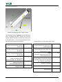
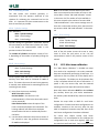
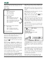
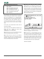
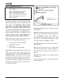
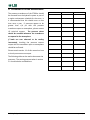
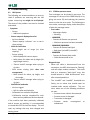
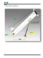
LMI System Load Moment Indicator Calibration Guide Using the pressure transducer kit part number: PT001xx WARNING! The LMI system is designed as an operator aid and is no way a substitute for safe operating practice. WARNING! THE LMI SYSTEM MUST BE INSTALLED BY QUALIFIED PERSONNEL. Failure to do so will void product liability and warranty. LSI can verify calibration accuracy should it be required. WARNING! Carefully read and understand this manual before proceeding. Page intentionally left blank Ordering Information ............................................................................................................................ ii 1. Installation of pressure transducers. ............................................................................................... 1 1.1. Requirements for an LMI system. ......................................................................................................... 1 1.2. Locating transmitter and pressure transducers ..................................................................................... 2 1.2.1. Consideration for transmitter location .................................................................................................................... 2 Mounting transducers directly on or near boom lift cylinder .............................................................................................. 2 Mounting transducers at a remote location ......................................................................................................................... 2 1.2.2. Consideration for transducers location ................................................................................................................... 2 Location for Piston side......................................................................................................................................................... 2 Location for Rod side ............................................................................................................................................................ 2 1.2.3. Routing the cables ................................................................................................................................................... 2 2. LMI setup and calibration ............................................................................................................... 3 2.1. Preparations for LMI calibration ........................................................................................................... 3 2.1.1. Verify “Sensor List” .................................................................................................................................................. 3 2.1.2. Select a load chart ................................................................................................................................................... 3 2.1.3. Collecting geometry information............................................................................................................................. 3 Basic information ................................................................................................................................................................. 4 Cylinder geometry................................................................................................................................................................ 5 Hoisting Cable geometry ...................................................................................................................................................... 6 Pick Points geometry ........................................................................................................................................................... 6 2.2. Display programming........................................................................................................................... 7 4B- Sensor Calibration- Angle sensor ........................................................................................................................................ 7 4C- Radius and Height Settings ................................................................................................................................................. 7 4G- Load Moment Indicator menu ............................................................................................................................................ 7 4G1A - Cylinder settings ....................................................................................................................................................... 8 4G1B - Hoist settings............................................................................................................................................................. 8 4G1C - Point settings............................................................................................................................................................. 8 2.3. 4G2- Main boom calibration ................................................................................................................ 8 4G2A – Radius ........................................................................................................................................................................... 9 4G2B - Boom Deflection without load .................................................................................................................................... 10 4G2C - Load Moment (No Load) ............................................................................................................................................. 11 4G2D - Boom Deflection (Under Load) ................................................................................................................................... 12 4G2E - Load Moment (Under Load) ........................................................................................................................................ 12 4G2F – Heavy Lift .................................................................................................................................................................... 13 4G2F1 – Heavy Lift .............................................................................................................................................................. 14 4G2F2 – Auto Adjust Piston Diameter ................................................................................................................................ 14 2.4. 4G3- Additional Boom Sections Calibration .........................................................................................15 4G3A - Radius .......................................................................................................................................................................... 15 4G3B - Load Moment (No Load) ............................................................................................................................................. 16 4G3C - Load Moment (Under Load) ........................................................................................................................................ 16 3. Scheduled PT001xx maintenance .................................................................................................. 18 GM009_ENG_rev20121102 i 4. Troubleshooting ........................................................................................................................... 19 4.1. LMI System.........................................................................................................................................19 4.2. PT001xx pressure sensor.....................................................................................................................19 Annex ................................................................................................................................................. 20 Annex 1: Cylinder area geometry ...................................................................................................................20 Annex 2: Hoist area geometry ........................................................................................................................21 LMI Checklist for Main Boom Calibration ............................................................................................. 22 Ordering Information Model Description PT00100-001 Pressure transmitter (902-928MHz) with sensors for rod (3.6KPSI) and piston (3.6KPSI) pressures PT00120-001 Pressure transmitter (868-870MHz) with sensors for rod (3.6KPSI) and piston (3.6KPSI) pressures SH005 Replacement pressure sensor 3.6KPSI TA011 Replacement sensor antenna GM009_ENG_rev20121102 ii About this guide: this guide assumes that the reader is familiar with navigation in the display unit menus. If help is needed for navigation in the menus, please consult the GS820 user manual. This guide is formatted to write values directly in the manual. Please take as many notes as possible as this helps the LSI engineer to assist you if needed. IMPORTANT SAFETY NOTE: the display unit and this manual will propose angles and lengths for calibrations points. Those are ideal recommendation points for the mathematical calculations. It does not mean that the crane is able to reach those points and that it is safe to reach those points. Ensure that the crane always stays within the safe load chart regions. In calibration mode, the display will not generate an alarm in case of overload with the load charts. No lockouts will be activated. When possible, use chain to attach the four corners of the crane to a slab of concrete to prevent all the possibilities of tipping the crane. If this is not possible, use extreme care when calibrating as the display will not generate any alarms. WIND CONDITION - IMPORTANT NOTE: wind speed above 8 mph will not permit to calibrate the crane with accuracy. Some of the tools to bring on site USB flash memory devices known to work correctly with LSI displays in order to make a backup of the system calibration once done. A digital camera is an essential tool to take pictures of the crane and get engineering support. A list of the crane boom configurations and boom attachments, such as jibs or auxiliary boom tips. This will help prepare the different steps of calibration. An inclinometer for machine geometry measurement. A measuring tape that is at least as long as machine boom length and should have a minimum 0.1’ resolution. GM009_ENG_rev20121102 WARNING! The calibration is formatted to ensure that the displayed value will be above the actual value. In light load lifting condition, the system may not meet the local regulation standard. 1. Installation of pressure transducers. 1.1. Requirements for an LMI system. For the LSI LMI system, it is vital that the hydraulics are setup so that if there are multiple boom-lift cylinders, that the pressures on the piston and rod of the cylinders is the same. IMPORTANT SAFETY NOTE: The directions for installing an LSI LMI system do not cover the procedures for working with hydraulics. Recommended manufacturer procedures for the crane should be used for safety and environmental concerns when working with the hydraulics. To verify that the transducers are in the expected zero condition, follow this procedure: 1. Make sure any adapters are removed from the pressure transducers. Ensure the transducer is not in direct sunlight and do not hold the transducers in your hand during the verification. 2. Add the “Pressure sensor” to the GS820 sensor list (Menu 4A). 3. Go into Diagnostic- System Sensors (Menu 5A) and select the pressure sensor. 4. Collect the following information: Transmitter ID: 3) Raw value (psi) : 9) Raw value 2(psi): 5. If the pressures recorded are greater than +/-4 psi, please contact LSI technical support. Page 1 of 22 1.2. Locating transmitter and pressure transducers The location for the transmitter and pressure transducers must be considered together. Generally, this is dictated by where the pressure transducers will be located. They can be installed directly onto the cylinders or at a remote location. 1.2.1. Consideration for transmitter location The transmitter comes attached to a mount plate. The mount plate can be welded, attached with threaded studs, or bolted to the machine. It is necessary to remove the mount plate from the transmitter if this plate is to be welded. Mounting transducers directly on or near boom lift cylinder When mounting the pressure transducers directly on or near the boom lift cylinder, most of the cables will be used to run along the hydraulic hoses. Usually selecting a location near the hydraulic swivel is ideal for the transmitter. Here, the hoses terminate and a minimal amount of excess cable will need to be used to transition off the hose(s). It is also recommended that the transmitter be located where its signal can be transmitted with minimal amount of objects between it and the display. Mounting transducers at a remote location If mounting the transmitters at a remote location, a majority of the cable will be used to run to the transmitter location. It is important that the hydraulic line for the transducers is constrained by attachment to a tab or tie-down. The pressure transducer cables are not designed to provide support for the pressure transducer or the hydraulic line. In most cases, the transmitter could be located near the transducers. However, if there are concerns of physical interference with movement of the cylinders or the boom, move the transmitter away. Ensure 6 inches of clearance of metal around the transmitter antenna, to ensure good reception in the cab. Locate the transmitter where there is a minimal amount of objects between the transmitter and display. GM009_ENG_rev20121102 1.2.2. Consideration for transducers location Whether transducers are located at the cylinders or at a remote location, the movement of the crane during all functions must be considered. The pressure transducers, hoses, and cables must not interfere with any range of motion during all crane functions. Also, considerations should be made of the work area around the installation location. Tees and 90 degree elbows should be used to keep the transducers from being able to be easily damaged or cause a safety hazard when working around them. Location for Piston side The pressure transducer that monitors the pressure on the boom lift cylinder piston should tie into the hydraulics between the holding valve and the cylinder piston. The hydraulic block mounted to the cylinder will most often have a port to monitor this pressure. Here, the transducer or a hose to a remote location can be applied. For machines with more than one boom-lift cylinder, this will be occupied by a hose that ensures there is identical pressure in both cylinders. In this case, a tee would need to be added for the pressure transducer. Location for Rod side The pressure transducer that monitors the back (rod) side of the piston can tie in anywhere along the return line from the cylinder, but is best to locate it near the other transducer. This will simplify running the cables between the transmitter and both transducers. A tee will need to be used to tie into the return line. 1.2.3. Routing the cables The cables should be routed to the transducers and secured to prevent damage the sensor itself or other parts of the machine. The routing should be such that any movement of the crane will not result in the cable being pulled or prone to snag on anything during crane functions. Items to be aware of are any flexing of the hose, pivoting hose joints, and any change that occurs between two surfaces that the cable is attached. Note: Before continuing operate the machine checking for unexpected interferences or binding. Page 2 of 22 2. LMI setup and calibration The interface of the LMI system is set up in a manner that steps the user through the process of the installation to ensure that set up is complete and simple to follow. After system sensors are installed LMI setup can begin. Setup and calibration instructions should be read before beginning. The system is calibrated to display the weight at the pick point. Any additional components that are attached or erected but are not integral to the active pick point will be included in the calculated weight. Components that are regularly stowed, such as jibs, will be calibrated such that they will not affect the calculated weight and its effect will be reduced load chart capacity. 2.1. Preparations for LMI calibration Here is a list of items to verify prior to start of LMI calibration: 1) Verify the sensor list 2) Select a load chart 3) Collect and verify that all the geometry information is known and is accurate 2.1.1. Verify “Sensor List” Confirm in menu 4A that all the required sensors are installed. These are: ‘Angle’, ‘Length’, ‘Radius’, ‘Pressure’, and ‘LMI load indication’. Depending on the chart loaded into the display, other sensors such as ‘slew’ sensor might also be required by the display in order to operate properly. Sens Sensor type Description or # 1 Pressure sensor 2 3 Angle sensor Length sensor 4 7 Radius sensor (Note 1) Tip Height (Note 1) LMI Load Indication (Note 2) LMI Load Indication 8 Slew sensor (Note 3) 5 6 GM009_ENG_rev20121102 Required. One sensor reads and sends two pressure readings. Required Required, usually the same ID as the angle. Required for majority of load charts. Required Required: Main hoist load calculation Optional: needed if there is an auxiliary hoist Required for systems using chart area management. Note 1: Radius and Tip Height are virtual sensors. The Radius sensor is mandatory for load chart access. The Tip Height is used by the LMI and can be utilized in the estimation of line weight during calibration. Note 2: If the crane has two hoists, there must be two ‘LMI load indication’ sensors, each one of these virtual sensors representing one hoist. Note 3: A system that is utilizing the optional feature of Chart Area Management must have a slew sensor defined. Here, a proper chart will be selected according to the relative position of the boom as defined in the manufacturer’s load chart. 2.1.2. Select a load chart Access the menu “2) Crane Rigging” and select a load chart. It is suggested to start calibration with a load chart for the main boom and the main hoist and without jibs, auxiliary boom tips, and similar attachments. If the system indicates that no load charts are loaded, go to menu 4D) and ensure item #1, “Rated capacity indicator”, is set to yes. Note: on an LMI system, contrary to traditional LSI RCI systems, only one hoist can be the current ‘working hoist’. Selecting a load chart for the auxiliary hoist will make the auxiliary hoist to be the ‘current hoist’. When the operator wants to work from the main hoist, he must rig one of the main hoist load charts on the main hoist. 2.1.3. Collecting geometry information Important: the geometry information is crucial to obtain the most accurate load calculation. An error in the geometry could be noticed only at the end of the calibration process. Values not accurate may affect the accuracy and make the system difficult to calibrate. It is better to verify every parameter twice to catch any error before starting the calibration process. Page 3 of 22 Basic information Important: before beginning calibration, verify boom length sensor accuracy by retracting and extending the boom and confirm readings on the main screen. Measure and record the boom length with a tape as the manufacturer may not use the same endpoints as the ones required by this system. The boom length is shown in the annex 2. Record these values in the chart. Crane Manufacturer Machine Model Number Rope Size Inches (Optional) Boom Cylinder Piston Bore Circumference Inches Boom Cylinder Piston Bore Diameter See (1) in picture below (Divide Circumference by 3.1416 and Subtract 1) Inches Boom Cylinder Rod Circumference (Optional) Boom Cylinder Rod Diameter See (2) in picture below (Divide Circumference by 3.1416) LOWER SHEAVE RADIUS Measure lower sheave radius on boom tip SLEW OFFSET Refer to user manual for detail BOOM FOOT HEIGHT Measure the distance of the center of the boom foot pin to ground BOOMLENGTH - retracted Inches BOOMLENGTH – extended This is the longest boom length available on this crane including manual extensions, but excluding jibs Existing Pressure Fitting Feet Inches Feet Feet Feet Feet 2 1 Tip to find Rod diameter: it is sometimes easier to measure the circumference in inches and divide it by 3.1416. D=C/π Tip to find the Piston Bore diameter: measure the circumference, divide it by 3.1416, and subtract 1 inch for the wall thickness. GM009_ENG_rev20121102 Page 4 of 22 Cylinder geometry Cylinder area geometry-larger image in annex The following values are optional, but recommended. After completing this table, contact LSI technical support who will be able to provide the values used by the LMI system. It is also recommended to have the boom hoist cylinder fully retracted. Leg BC Center-to-center distance between pins B and C. Leg AC Center-to-center distance between pins A and C. Leg AB Center-to-center distance between pins A and B. Angle BA Angle of cylinder to ground. Subtract from 180° if B is forward of A. Does A and C sit on the same plane relative to the boom? Ignore question below if YES Is A below the axis of the boom pivot along the boom? GM009_ENG_rev20121102 Feet Cylinder geometry values used by LMI system. P2BLV Feet Vertical distance from boom pivot to cylinder base pin. Feet P2BUH Feet Distance along the boom from boom pivot to cylinder rod pin. Feet Degrees Yes / No P2BLH Feet Horizontal distance from boom pivot axe to cylinder base pin. S Feet Vertical distance from boom pivot axe to cylinder rod pin (value is negative if pin is below the boom pivot). Number of cylinders Yes / No Rod diameter Inches Bore diameter Inches Page 5 of 22 Hoisting Cable geometry Pick Points geometry For cranes where the hoist drum IS NOT attached to the boom, the following values are needed. The geometry of the pick points must be measured and entered for each of the pick points set in the system. Main boom head Feet C Vertical distance from boom pivot axe to upper sheave Feet RTOPSHEAVE Upper sheave radius. Auxiliary boom head C Feet Vertical distance from boom pivot axe to upper sheave Hoist area geometry-larger image in annex RTOPSHEAVE Upper sheave radius. Values for main hoist: P2CHV Feet Vertical distance from boom pivot axe to hoist drum. P2CHH Jib #1 pick point geometry C Feet Horizontal distance from boom pivot axe to hoist drum. RHOIST Feet Jib #2 pick point geometry Values for the auxiliary hoist: Feet Vertical distance from boom pivot axe to hoist drum. Hoist drum radius GM009_ENG_rev20121102 Feet Vertical distance from boom pivot axe to upper sheave RTOPSHEAVE Feet Upper sheave radius. Feet Horizontal distance from boom pivot axe to hoist drum. RHOIST Feet Upper sheave radius. C P2CHH Feet Vertical distance from boom pivot axe to upper sheave RTOPSHEAVE Hoist drum radius P2CHV Feet Feet Tip: take digital photos of the side of the crane. This gives a tool to a LSI engineer to confirm the dimensional measurements or for a review later on. To prevent ‘fish eye’ type of deformations in the photo, it is preferable to move a distance away from the crane and zoom into the crane with the digital camera. Take photos of the whole crane side, then the cylinder area and the boom tip. Make sure the images include an object of known size. Page 6 of 22 2.2. Display programming 4B- Sensor Calibration- Angle sensor Sensitivity for the angle sensor must be increased for LMI accuracy. Follow the procedure to make this adjustment to the calibration of the angle sensor: 1. 2. 3. 4. 5. 6. 7. Enter menu 4B) Sensor Calib Enter menu 4B2) Manual Calibration Select Angle ID: XXXXX Select item 4) Sensitivity Change/confirm value is set to 150 Press Exit to leave menu Press Enter to save 4C- Radius and Height Settings The menu for radius and height settings contains information that must be set for the LMI to function properly. The necessary items for the radius sensor will be defined automatically during the calibration process. However, tip height needs to be defined manually. When entering 4C) Radius and Height settings, the user will be asked to select the pick point. Highlight “Main boom” and press confirm. Items 2) and 3) need to be updated 2) Boom foot height offset- Enter the value recorded earlier in the manual. 3) Tip height tolerance- For the purposes of the LMI system, this value can be set to zero. If objects protrude above the boom upper sheave and are a concern in the machines work environment, please consult the 820 manual or LSI technical support. GM009_ENG_rev20121102 4G- Load Moment Indicator menu The menu for the load moment indicator provides access to the different steps of calibration in the order that they must occur. 4G – Load Moment Indicator menu content: 4G1 –Geometry 4G1A - Cylinder Settings 4G1B –Hoist Settings 4G1C –Point Settings 4G2 – Main Boom Calibration 4G2A – Radius 4G2B – Boom Deflection (No Load) 4G2C – Load Moment (No Load) 4G2D – Boom Deflection (Under Load) 4G2E – Load Moment (Under Load) 4G2F – Heavy Lift 4G3 – Additional Boom Sections Calibration 4G3A – Radius 4G3B – Load Moment without load 4G3C – Load Moment under load 4G4 – Advanced settings 4G4A – Record Extra Points 4G4B – Edit Boom Calibration 4G4C – Edit Section Calibration 4G4D – LMI Filters Page 7 of 22 4G1- Geometry for LMI The LMI system uses machine geometry in cooperation with the pressure observed at the cylinders for calculating the measured load on the hook. It is important for these measurements to be done as accurately as possible. 4G1A - Cylinder settings 4G1 –Geometry 4G1A - Cylinder Settings 4G1B – Hoist Settings 4G1C – Point Settings Cylinder settings are geometric dimensions around the boom base pin and the boom cylinder area. Enter in the display the measurements made in the previous section of this manual. The number of cylinders should have a value of 1 or 2, depending on the number of cylinder(s) lifting the boom. 4G1B - Hoist settings 4G1 –Geometry 4G1A - Cylinder Settings 4G1B –Hoist Settings 4G1C –Point Settings Cranes typically have two hoists, a main hoist and an auxiliary. Hoist data must be collected for each of them. This means that once the main hoist geometry is entered, menu 4G1B must be entered again for the remaining shown hoists. 1) Hoist (three choices are available): With hoist radius: default No Hoist Radius: this selection is not recommended (it is if the hoist drum radius could not be measured) Hoist fixed on boom: select this option if this hoist is mechanically fixed to the main boom. The hoisting cable will not affect the crane boom moment when the hoist is mechanically fixed to the boom. 2) Use the values collected in the previous section of this manual to enter the geometric dimensions for each hoist displayed. GM009_ENG_rev20121102 Note: if the number of hoists offered in the menu does not correspond to the number of hoists on the crane, add or remove “LMI Load Indication” sensors in the sensor list. The number of hoists available in this menu is equal to the number of sensors called “LMI Load Indication” in the sensors settings menu. If there are a main and an auxiliary hoist, there must be two sensors called “LMI Load Indication” in the menu 4A. 4G1C - Point settings 4G1 –Geometry 4G1A - Cylinder Settings 4G1B –Hoist Settings 4G1C - Point Settings This menu contains geometric dimensions to enter for each of the pick points. Access the menu as many times as there are pick points to set. Use the measurements made in the previous section of this manual. 2.3. 4G2- Main boom calibration The “Main Boom Calibration” is divided into steps that need to be completed in the order presented. Steps are completed by performing all sub-steps. It is important to not turn power off on the display until a step is complete. The display can be shut down after a step is complete without any loss of information. If power is lost, the current step must be restarted meaning that all sub-steps will need to be redone. Note: Main boom calibration MUST be done without jibs, auxiliary boom tips, and similar attachments. Any auxiliary cable should be fully wound on the hoist drum. Execute the steps 4G2A to 4G2E for each boom configuration. If several main boom configurations are available, continue to the next only after the step 4G2F is completed. Proceed to step 4G3 after all the main boom configurations have been calibrated. For cranes that require several main boom calibrations, it is recommended to first calibrate the configuration that is used most regularly AND uses the main hoist and hook block. Only in extreme cases Page 8 of 22 where the main hoist and hook block are rarely used should the initial main boom calibration use the auxiliary hoist. 4G2A – Radius 4G1 –Geometry 4G1A - Cylinder Settings 4G1B –Hoist Settings 4G1C – Point Settings 4G2 – Main Boom Calibration 4G2A – Radius 4G2B – Boom Deflection (No Load) 4G2C – Load Moment (No Load) 4G2D – Boom Deflection (Under Load) 4G2E – Load Moment (Under Load) 4G2F – Heavy Lift 4G3 – Additional Boom Sections Calibration 4G3A – Radius 4G3B – Load Moment (No Load) 4G3C – Load Moment (Under Load) pages does not match the boom configuration just selected. Follow the steps to select the correct chart. Step 1 of 4: Enter the sheave radius at the boom tip and confirm. This value was recorded earlier in this manual. Step 2 of 4: Enter slew offset and confirm. This value was recorded earlier in this manual. Note: On most cranes, slew offset should be a negative value. This occurs when the center of rotation is in front of the boom foot pin. Step 3 of 4: Fully retract the boom and raise the boom to the maximum angle. Measure the crane radius from the center of rotation to the load point at the hook block or lifting ball. Adjust the value on screen and confirm. Step 4 of 4: With the boom still retracted, lower boom to the minimum angle and measure the radius. Adjust the screen value. 4G4 – Advanced settings … The Radius tool assists in adjusting the radius value used by the GS820 display. Radius must be accurate because it is used to calculate the LMI load. Note: Before starting Radius calibration, make sure to confirm that the proper parts of line is set. The same parts of line must be used for the entire main boom calibration. Select the boom configuration to calibrate: upon starting the radius calibration, select the load chart corresponding to the current crane configuration. It is preferred to begin with the main boom without jibs, auxiliary boom tips, and similar attachments. It is important that the pick point remain unchanged during main boom calibration. Confirm the hoist being calibrated. The hoist should not be changed during main boom calibration. Note: if the display indicates: “The chart rigged must reflect the configuration to be calibrated”, this means that the load chart selected in the main operating GM009_ENG_rev20121102 The raw data shown on screen is the radius as estimated by the system with the information it already knows. It may or may not be near the real value. Upon completion, calculated values for “Sheave Head Length Parallel to boom” and “perpendicular to the boom” will be displayed. These values should be similar to distance between upper and lower boom tip sheaves, but it also absorbs some imperfections, so some discrepancy is expected. Radius should be confirmed by exiting to the main screen and moving to a few different boom angles. Page 9 of 22 4G2B - Boom Deflection without load 4G2 – Main Boom Calibration 4G2A – Radius 4G2B – Boom Deflection (No Load) 4G2C – Load Moment (No Load) 4G2D – Boom Deflection (Under Load) 4G2E – Load Moment (Under Load) 4G2F – Heavy Lift Step 3 of 3: Fully extend the boom to maximum length allowed in this configuration and boom mode. Main boom can be at a steep angle for extension. Position the boom at 45° and measure from the center of rotation to the load point at the hook block or lifting ball. For most machines, this value should measure longer than the “Raw data” value displayed. Adjust value and press Enter. This step adjusts the radius to account for standard boom deflection. This includes deflection of the boom sections and between the boom sections. Deflection will not be accounted for on a retracted boom. Deflection calculation starts when the boom begins to be extended. Note: boom deflection does not increase the radius when the boom is at zero degrees. For this reason, the test must be made at a higher angle. At this point, the retracted boom radius must be accurate at all angles. Upon starting the boom deflection calibration, the display will ask to select the current crane configuration and also current hoist. Step 1 of 3: Enter the value for retracted boom length that was recorded previously in the manual. Step 2 of 3: Enter the value for the maximum extended boom length with all telescoping sections extended, including manual and powered sections that was recorded previously in the manual. Upon completion, a calculated value for no load deflection is displayed. Press Enter to finish. Note: At this time, it is recommended to exit to the main screen and confirm radius and deflection values by moving the boom and measuring a variety of points at various angles and boom lengths. Measured and displayed values should be very close to each other. Typical radius accuracy should be around 1%, this would represent a 1 ft error at 100 ft radius. Continue to step 4G2C. GM009_ENG_rev20121102 Page 10 of 22 4G2C - Load Moment (No Load) 4G2 – Main Boom Calibration 4G2A – Radius 4G2B – Boom Deflection (No Load) 4G2C – Load Moment (No Load) 4G2D – Boom Deflection (Under Load) 4G2E – Load Moment (Under Load) 4G2F – Heavy Lift This step will calibrate the pressure transducers for the boom without any load. The hook block or lifting ball should be hoisted so that a minimal amount of cable remains. It is important for the last motion done with the crane before taking calibration data points to be a downward motion with the boom. The display will propose lengths and angles on screen. Those are recommendations; it is acceptable to be at different lengths and angles. The display may also suggest unreachable angles. Please make sure to stay within the load charts limit when calibrating. Upon starting the empty boom load moment calibration, the display will ask the following: Select the current crane configuration Select the current hoist Parts of line Enter the block or the ball weight Step 1 of 9: Fully retract the boom to the minimum length and position the boom above the recommended angle. Adjust angle ending with a downward motion. Allow sufficient time for the load and pressures to stabilize and confirm. If rod pressure on the machine remains elevated above 20 psi or if the pressures continue to change for more than 30 seconds, take the reading after 30 seconds. This has been proven successful. GM009_ENG_rev20121102 Step 2 & 3 of 9: Repeat for the next angles with fully retracted boom. Step 4 of 9: The display will provide a value for a midextension value for the boom. Adjust the angle past the recommended angle and extend to recommended boom length (mid-extension). Adjust angle down to recommended angle and allow pressures to stabilize. Press Enter to confirm. Step 5 & 6 of 9: Repeat for the next angles with midextension boom. Step 7 of 9: Adjust angle past the recommended angle and fully extend boom. Adjust angle down to the recommended angle and allow pressures to stabilize. Step 8 & 9 of 9: Repeat for next angles with fully extended boom. Press the Confirm button to conclude Load Moment (No Load) Calibration. Page 11 of 22 4G2D - Boom Deflection (Under Load) 4G2E - Load Moment (Under Load) 4G2 – Boom deflection under load 4G2A – Radius 4G2B – Boom Deflection (No Load) 4G2C – Load Moment (No Load) 4G2D – Boom Deflection (Under Load) 4G2E – Load Moment (Under Load) 4G2F – Heavy Lift 4G2 – Main Boom Calibration 4G2A – Radius 4G2B – Boom Deflection (No Load) 4G2C – Load Moment (No Load) 4G2D – Boom Deflection (Under Load) 4G2E – Load Moment (Under Load) 4G2F – Heavy Lift This step adds accuracy to the calculated radius by measuring the boom for deflection when under load. For this step a minimum weight of 66% of rated load at full extension and 60° boom angle. This step will calibrate the LMI system so that it will calculate the current load in the selected crane configuration. It is accomplished by lifting a known weight when fully retracted, mid-extension, and full extension. It is recommended to use 2-3 weights (one weight for each boom length or a heavier weight for the shorter boom lengths with a lighter weight for full extension). Each weight should be equal to 50 to 100% of rated capacity at the respective extension and 30°. Write down the known weight value. For safety when lifting the known weight, lift it only a few inches from the ground. Upon starting the boom deflection calibration, the display will ask the following: Select the current crane configuration Select the current hoist Lift the weight and position fully extended boom at 60°. Measure the distance from the center of rotation to the load point of the hook block. Adjust value on display and confirm. As previously, this value is expected to be larger than raw data value. The amount of wire rope then becomes important to obtain the accuracy. Add the wire rope weight to known weight. To estimate cable weight: CableWeight = (Tip Height) x (Nber of Parts) x CWpF CWpF Cable Weight per Foot could be estimated to the following: Cable diameter 9/16” 3/4 ” CWpF ½ lb per foot 1 lb per foot The total known weight is then the known weight + the cable weight + rigging. Hook block weight should NOT be included. Upon completion, a calculated value for under load deflection is displayed. Press ENTER to finish. GM009_ENG_rev20121102 All points are recommendations, so it is acceptable to be above or below this value. Always ensure that it is safe to lift the weight in the current crane configuration according to the load chart. The display will not generate an alarm in case of overload with the load charts. Page 12 of 22 The display will ask the following: Select the current crane configuration Select the current hoist Parts of line Enter the block or the ball weight Step 1 of 9: Fully retract the boom to the minimum length, lift the known weight, and position the boom above the recommended angle. Adjust angle ending with a downward motion and allow sufficient time for the pressures to stabilize. Step 5 & 6 of 9: Repeat for next angle with midextension boom. When complete, the weight can be set down and another weight moved into the work area for full-extension. Step 7 of 9: Adjust angle past the recommended angle and fully extend boom. Lift the full-extension weight and adjust the angle down to the recommended angle and allow pressures to stabilize. Step 8 & 9 of 9: Repeat for the next angles with fully extended boom. When complete, the weight can be set down. Press the Confirm button to conclude Load Moment (Under Load) Calibration. 4G2F – Heavy Lift Estimated weight Maximum from load charts Note: move the load with extreme care as the maximum shown from load chart is only an indication and no alarms will be generated, no lockouts will be activated. Double-check the maximum with paper copies of the load charts. Adjust the known weight on screen and add the estimated wire rope weight plus any pins or slings used. Step 2 & 3 of 9: Repeat for next angles with fully retracted boom. When complete, the weight can be set down and another weight moved into the work area for mid-extension. Step 4 of 9: The display will provide a value for a midextension value for the boom. Adjust the angle past the recommended angle and extend to recommended boom length (mid-extension). Lift the mid-extension weight and adjust the angle down to the recommended angle and allow pressures to stabilize. GM009_ENG_rev20121102 4G2 – Main Boom Calibration 4G2A – Radius 4G2B – Boom Deflection (No Load) 4G2C – Load Moment (No Load) 4G2D – Boom Deflection (Under Load) 4G2E – Load Moment (Under Load) 4G2F – Heavy Lift 4G2F1 – Heavy Lift Point 4G2F2 – Auto Adjust Piston Diameter This step will record a heavy lift data point and adjust the piston diameter. The piston area is adjusted to properly balance piston area with the rod area giving consistent results. It is recommended to do the heavy lift with the boom fully retracted and at a similar angle that was recorded during the load moment calibration. Note: If the crane requires more than one main boom calibration, the auto adjust piston diameter step should only be completed once and with the initial main boom calibration. Page 13 of 22 4G2F1 – Heavy Lift 4G2F – Heavy Lift 4G2F1 – Heavy Lift Point 4G2F2 – Auto Adjust Piston Diameter This sub step will require a load that is 50-100% of rated capacity for the crane. Write down the known weight value. No specific boom length or angle is required, but the load chart MUST be used to determine the position of load. For safety when lifting the known weight, lift it only a few inches from the ground. Step 1 of 3: Enter the block or the ball weight. Step 2 of 3: Lift a heavy load and boom down slightly. Allow sufficient time for the pressures to stabilize and press ENTER. Step 3 of 3: Enter the actual known weight that is attached to block, including weight for rigging and an approximation for the wire rope. Refer to chart in 4G2E for approximate wire rope weights. Press the Confirm button to conclude Heavy Lift. The display will then update all of the calibration data with the adjusted piston value. When the update has completed, press the ENTER key to confirm. Note 1: If previous calibration steps have been redone for any reason, the Auto Adjust Piston Diameter should be run again. Note 2: If the Auto Adjust Piston Diameter has previously been done, a message will appear to confirm that the user wants to run the utility again. Note 3: If the Auto Adjust Piston Diameter is being redone after several additional boom sections have been calibrated, it may take several minutes to complete. Congratulations. This main boom calibration is complete. Next step: repeat the section 4G2 for all the other main boom configurations of the crane. 4G1 –Geometry 4G1A - Cylinder Settings 4G1B –Hoist Settings 4G1C – Load Pick Point Settings 4G2F2 – Auto Adjust Piston Diameter 4G2F – Heavy Lift 4G2F1 – Heavy Lift Point 4G2F2 – Auto Adjust Piston Diameter This sub step is entirely automated. The display uses the heavy lift data point and compares this to the previously completed calibration data to adjust the piston diameter. The adjusted value will provide improved results across the loading spectrum of the machine. This step should only be done during the primary main boom calibration. Selecting Auto Adjust Piston Diameter from the menu screen will automatically execute the adjustment. After the display has calculated an adjusted piston value, a confirmation screen will appear showing the adjusted value and the original value. Select Yes to save this value. GM009_ENG_rev20121102 4G2 – Main Boom Calibration 4G2A – Radius 4G2B – Boom Deflection (No Load) 4G2C – Load Moment (No Load) 4G2D – Boom Deflection (Under Load) 4G2E – Load Moment (Under Load) 4G2F – Heavy Lift 4G3 – Additional Boom Sections Calibration 4G3A – Radius 4G3B – Load Moment (No Load) 4G3C – Load Moment (Under Load) 4G4 – Advanced 4G4A – LMI Filters 4G4B – Edit Boom Calibration 4G4C – Edit Section Calibration 4G4D – Record Extra Points Page 14 of 22 2.4. 4G3- Additional Boom Sections Calibration 4G1 –Geometry 4G1A – Cylinder Settings 4G1B – Hoist Settings 4G1C – Load Pick Point Settings 4G2 – Main Boom Calibration 4G2A – Radius 4G2B – Boom Deflection (No Load) 4G2C – Load Moment (No Load) 4G2D – Boom Deflection (Under Load) 4G2E – Load Moment (Under Load) 4G2F – Heavy Lift 4G3 – Additional Boom Sections Calibration 4G3A – Radius 4G3B – Load Moment (No Load) 4G3C – Load Moment (Under Load) The Radius tool assists to get the most accurate radius value for this boom attachment. Upon starting the radius calibration, the display will ask to confirm the following: The configuration or attachment to calibrate. The selected hoist Note: if the display proposes to rig the load chart corresponding to this new configuration, answer yes and select the right load chart. Step 1 of 4: Pick point sheave radius: enter the sheave radius at the tip of the selected attachment. Step 2 of 4: Slew offset does not vary. This step is automatically skipped. Step 3 of 4: Follow on screen instructions and enter the measured radius from the center of rotation to the hook position. 4G4 – Advanced settings 4G4A – LMI Filters 4G4B – Edit Boom Calibration 4G4C – Edit Section Calibration 4G4D – Record Extra Points It is necessary to calibrate the system with all the available additional boom attachments, such as jibs. The calibration for these attachments looks like the main boom calibration, but in a simplified version. A known weight of 60 to 90% of rated capacity for the configuration will be used. The hook block or lifting ball should be hoisted so that a minimal amount of cable remains. As in the previous steps, it is important for the last motion done with crane before taking calibration data points to be a downward motion with the boom. 4G3A - Radius 4G3 – Additional Boom Sections Calibration 4G3A – Radius 4G3B – Load Moment (No Load) 4G3C – Load Moment (Under Load) GM009_ENG_rev20121102 Step 4 of 4: With the boom still fully retracted, lower the boom to the minimum angle. Measure and adjust the radius. Upon completion, calculated values for “Sheave Head Length Parallel to boom” and perpendicular to the boom will be displayed. These values should be similar to distance between upper and lower boom tip sheaves, but they also include any deflection or other cause for discrepancy between theoretical and actual radius. Page 15 of 22 4G3B - Load Moment (No Load) 4G3C - Load Moment (Under Load) 4G3 – Additional Boom Sections Calibration 4G3A – Radius 4G3B – Load Moment (No Load) 4G3C – Load Moment (Under Load) 4G3 – Additional Boom Sections Calibration 4G3A – Radius 4G3B – Load Moment (No Load) 4G3C – Load Moment (Under Load) The display will ask to confirm: The configuration or attachment to calibrate. The selected hoist The number of parts of line The hook block or ball weight Step 1 of 3: Fully retract the boom to the minimum length and position the boom above the recommended angle. Adjust angle ending with a downward motion and allow sufficient time for the pressures to stabilize and confirm. This step requires a load of 50 to 100% of rated capacity with the boom fully extended at 20° or minimum allowed by load chart in this configuration. The display will ask to confirm: The configuration or attachment to calibrate. The selected hoist The number of parts of line The hook block or ball weight Step 1 of 4: Lift a known weight and position boom past the recommended angle. Adjust angle ending with a downward motion, allow pressures to stabilize and confirm the total weight (known weight + estimated cable weight + slings + pins). Step 2 & 3 of 3: Repeat for the next angles. Press the ENTER button to conclude Load Moment (No Load) calibration. GM009_ENG_rev20121102 Page 16 of 22 Step 2 of 4: Set the weight on the ground and extend the boom to maximum length. Position the boom at the recommended angle (confirm with load chart) ending with a downward motion. Step 3 of 4: With the boom fully extended, increase boom angle to pick up load. Position the boom at the recommended angle ending with a downward motion. Confirm the total weight (known weight + estimated cable weight + slings + pins). Step 4 of 4: Decrease boom angle to the recommended angle or minimum angle according to load chart (whichever is greater). Confirm the total weight (known weight + estimated cable weight + slings + pins). Press the Enter button to conclude Load Moment (Under Load) Calibration for this attachment. Repeat the sections 4G3A to 4G4C for all the other boom attachments. 4G3 – Additional Boom Sections Calibration 4G3A – Radius 4G3B – Load Moment (No Load) 4G3C – Load Moment (Under Load) Congratulations! Calibration is complete! It is recommended to copy the LMI file from the display and stored in a known location on a PC. To copy the LMI file from the display, insert a USB thumb drive into the GS820 display and select, “Copy LMI configuration to USB”. This file contains all the calibration information and sensor configuration for the machine. Important: At this time, the LMI calibration file must be evaluated to ensure the quality of the resulting calibration. This can be done by submitting the calibration file to LMI tech support at [email protected]. GM009_ENG_rev20121102 Page 17 of 22 3. Scheduled PT001xx maintenance The pressure transducers of the PT001xx should be removed from the hydraulic system as part of a regular maintenance schedule for the crane. It is recommended that this should occur no less than once a year. If pressures appear to be greater than +/-4 psi with the pressure transducers open to atmosphere, please contact LSI technical support. The pressure values should be recorded whenever the transducers are opened to the atmosphere. Date Rod Pressure (3) Piston Press. (9) If loads are ever observed to be reading inaccurately, checking the pressure sensors output with the transducers open to atmosphere should be confirmed. Please consult section 1.1 of this manual on how to check pressure sensor output. The following table can be used to document the pressures. The starting pressure taken in section 1.1 should also be recorded here. GM009_ENG_rev20121102 Page 18 of 22 4. Troubleshooting 4.1. LMI System The following are recommendations as items to check if problems are occurring with the LMI system concerning no weight to be displayed. The cause of the problem can then be isolated and solved. - Symptom - Causes o Additional symptoms - Sensor output is displayed as a list. - No chart loaded - “Rated capacity indicator” set to no in chart settings. - NoRx for load value - Boom length out of range (no chart capacity) - Sensor missing o NoRx displayed for sensor output. o NoRx shown for radius and tip height (for angle/length sensor). o “Sensor Invalid” message when trying to rig chart. - Slew sensor missing (with chart area management) o NoRx shown for radius, tip height, and slew angle. o “Sensor Invalid” message when trying to rig chart. - NotCalib for load value - No chart rigged o N/A for radius and tip height - Calibration has not been completed Calibration must be completed for main boom and any additional section selected. If the machine had been previously calibrated and all sensors are working, it is recommended to reload LMI+CFG file into the display. This will reset any settings that may have changed and causing issues. GM009_ENG_rev20121102 4.2. PT001xx pressure sensor Error messages can be viewed in two ways. The messenger at the top of the GS820 display or by going into menu 5A) and selecting the pressure sensor to view the error code. The following are error codes, messenger display, and a description of what this message means: - Error codes - Messenger display o Meaning - 100000000 - Pressure id Gxxxxxx over pressure o Maximum pressure has been exceeded - 200000000/300000000 - Pressure id Gxxxxxx bad signal o Bad signal (<minADC/>maxADC) - 40000000x - Pressure id Gxxxxxx faulty cable o Cable disconnected or cut Diagnostic tips - When the cable is disconnected from the transmitter, the ADC value becomes “floating” and will output random numbers. This could lead to a temporary “bad signal” error, but should become a “cable disconnected” error after some elapsed time. - The “minADC” and “maxADC” thresholds are factory set to values that should never be reached under normal utilization. This can occur when one of the following conditions are met: o Pressure sensor cable is disconnected o Pressure sensor is damaged o Transmitter is damaged o Pressure sensor unrecognized or unbalanced Page 19 of 22 Annex Annex 1: Cylinder area geometry GM009_ENG_rev20121102 Page 20 of 22 Annex 2: Hoist area geometry GM009_ENG_rev20121102 Page 21 of 22 LMI Checklist for Main Boom Calibration Before Installation Page Manufacturer processes have been reviewed BEFORE opening hydraulic circuit. 1 Location of transmitter and transducers has been determined. 2 After Installation Run the machine through motions checking for binding of wires or physical interferences. 2 Pre-Calibration Sensor list has been verified (Menu 4A). 3 Load chart has been rigged (Menu 2). 3 Verification of boom length sensor accuracy. 4 All geometry values have been collected. 3-6 All geometry values have been verified. 3-6 Values for Radius and Height Settings have been programmed into display (Menu 4C). 7 Values for Cylinder Settings have been programmed into display (Menu 4G1A). 8 Values for Hoist Settings have been programmed into display (Menu 4G1B). 8 Values for Point Settings have been programmed into display (Menu 4G1C). 9 Calibration Confirm parts of line before starting radius (Menu 1). 9 Radius calibration complete (Menu 4G2A). 9 Radius has been checked and verified (fully retracted). 9 No-load deflection complete (Menu 4G2B). 10 After no-load deflection, radius at various boom lengths and angles has been verified. 10 9-point no-load calibration complete (Menu 4G2C). 11 Under-load boom deflection is complete (Menu 4G2D). 12 9-point under-load calibration is complete (Menu 4G2E). 12-13 Heavy lift point is complete (Menu 4G2F1). 14 Auto adjust piston diameter has been performed (Menu 4G2F2). (First main boom calibration ONLY!) 14 Post-Calibration Retrieve LMI calibration file from GS820 display. 17 Review/submit LMI calibration file to for calibration evaluation [email protected]. Store calibration on a PC for future reference. 17 GM009_ENG_rev20121102 17 Page 22 of 22