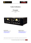
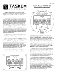
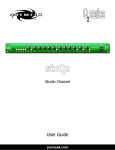
1
______________________________________________________________________________________________________________________________ User’s Manual Compactor Zener compressor / limiter Gem Audio Labs Tel. : 00 48 508 377 982 [email protected] www.gemaudiolabs.com Rev.2 Date 03.07.2012 Page 1 / 14 ___________________________________________________________________________________________________________________________ CE Conformity We declare with sole responsibility that this product complies with the following norms and directives: 2006/95/EC LVD (Low Voltage Directive) 2004/108/EC EMC (Electromagnetic Compatibility) DIN EN 55103-1 EMC of audio equipment- Emission DIN EN 55103-2 EMC of audio equipment- Immunity This declaration becomes invalid by any unapproved modification of the device. Wroclaw, 02.06.2011 B. Radziszewski SPLASH BARTOSZ RADZISZEWSKI Wietrzna 36/1 53-024 Wroclaw POLAND VAT Reg. Nr : PL8862784446 Rev.2 Date 03.07.2012 Page 2 / 14 ___________________________________________________________________________________________________________________________ TABLE OF CONTENTS INTRODUCTION ................................................................................................................................ 4 FOR SAFE OPERATION ..................................................................................................................... 4 CAUTION .............................................................................................................................................. 5 FOR CORRECT OPERATION ........................................................................................................... 6 DESIGN .................................................................................................................................................. 6 THE FRONT PANEL CONTROLS AND THEIR USE .................................................................. 7 THE REAR PANEL ............................................................................................................................. 10 BLOCK DIAGRAM ............................................................................................................................ 11 TECHNICAL DATA........................................................................................................................... 12 ENVIRONMENTAL PROTECTION .............................................................................................. 13 LIMITED WARRANTY ..................................................................................................................... 14 Rev.2 Date 03.07.2012 Page 3 / 14 ___________________________________________________________________________________________________________________________ INTRODUCTION First of all, we would like to thank You sincerely for choosing this GEM AUDIO LABS Compactor which combines ease of operation with support for multiple usage environments. As a company and first of all, as fans of pro audio devices, we do our best in our daily work to satisfy your most sophisticated sound expectations. We put in your hands the highest quality product, precisely designed and hand manufactured by our qualified staff, without any compromise. To build our devices we use only the best, hand-selected electronic components, we take care about all parameters repeatability and high quality of all our products. Please take a little time to read this manual thoroughly, as it will help You to entirely understand how the Compactor works and what is important to use it safely. Gem Audio Labs team. FOR SAFE OPERATION INSTALLATION Before You connect the power cord to the device please check fuses value and make sure that the voltage switch setting reflects the correct local power line voltage. For line voltages from 100V to 120V, set the switch to 115V and use 1A fuses (slo-blo; 5x20mm). The 230V position is good for all line voltages from 200-240Volts; fuses: 500mA (slo-blo; 5x20mm). This unit is equipped with a three-pronged AC power cord. To reduce the risk of electrical shock never remove or otherwise attempt to defeat the ground pin of the power cord. Do not allow water to enter this unit or allow the unit to become wet. Fire or electrical shock may result. Do not place a container with liquid or small metal objects on top of this unit. Liquid or metal objects inside this unit are a fire and electrical shock hazard. Do not place heavy objects, including this unit, on top of the power cord. A damaged power cord is a fire and electrical shock hazard. Rev.2 Date 03.07.2012 Page 4 / 14 ___________________________________________________________________________________________________________________________ OPERATION Do not scratch, bend, twist, pull, or heat the power cord. A damaged power cord is a fire and electrical shock hazard. Do not remove the unit’s cover. You could receive an electrical shock. If you think internal inspection, maintenance, or repair is necessary, contact your dealer or producer. Do not modify the unit. Doing so is a fire and electrical shock hazard. If lightning begins to occur, turn off the power switch of the unit as soon as possible, and unplug the power plug from the electrical outlet. If there is a possibility of lightning, do not touch the power plug if it is still connected. Doing so may be an electrical shock hazard. Use only the included AC power cord for this unit. Using other types may be a fire and electrical shock hazard. IN CASE AN ABNORMALITY OCCURS DURING OPERATION If the power cord is damaged (i.e., cut or a bare wire is exposed), ask your dealer or producer for a replacement. Using the unit with a damaged power cord is a fire and electrical shock hazard. Should this unit and AC cord be dropped or the cabinet be damaged, turn the power switch off, remove the power plug from the AC outlet, and contact your dealer or producer. If you continue using the unit without heeding this instruction, fire or electrical shock may result. If you notice any abnormality, such as smoke, odor, or noise, or if a foreign object or liquid gets inside the unit, turn it off immediately. Remove the power plug from the AC outlet. Consult your dealer or producer for repair. Using the unit in this condition is a fire and electrical shock hazard. CAUTION INSTALLATION Keep this unit away from the following locations: Locations exposed to oil splashes or steam, such as near cooking stoves, humidifiers, etc. Unstable surfaces, such as a wobbly table or slope. Locations exposed to excessive heat, such as inside a car with all the windows closed, or places that receive direct sunlight. Locations subject to excessive humidity or dust accumulation. Hold the power plug when disconnecting it from an AC outlet. Never pull the cord. A damaged power cord is a potential fire and electrical shock hazard. Do not touch the power plug with wet hands. Doing so is a potential electrical shock hazard. Rev.2 Date 03.07.2012 Page 5 / 14 ___________________________________________________________________________________________________________________________ To relocate the unit, turn the power switch off, remove the power plug from the AC outlet, and remove all connecting cables. Damaged cables may cause fire or electrical shock. OPERATION Do not cover this unit and use it only in a well-ventilated environment. If you know you will not use this unit for a log period of time, such as when going on vacation, remove the power plug from the AC outlet. Leaving it connected is a potential fire hazard. FOR CORRECT OPERATION CONNECTOR PIN ASSIGNMENTS XLR connectors (INPUT, OUTPUT) are wired according to the AES standard : Pin 1 = shield, Pin 2 = hot (+), Pin 3= cold (-). INFLUENCE ON CELL PHONE USAGE Using a cell phone (mobile telephone) near this unit may induce noise. If noise occurs, use the telephone away from the unit. REPLACING ABRASIVE PARTS AND CLEANING THE UNIT The performance of components with moving contacts, such as toggle switches, rotary switches and connectors, deteriorates over time. The rate of deterioration depends on the operating environment and is unavoidable. Consult your dealer or producer about replacing defective components. Clean this unit only with lint-free damp cloth and do not use cleaning agents. DESIGN The GEM AUDIO LABS Compactor is a two channel (stereo/dual mono) pure analog (ClassA, discrete) dynamic processor, in which the gain reduction is made by a discrete VCA based on bipolar transistors and Zener diodes. ENCLOSURE Compactor’s enclosure is a solid (2U high) and compact construction based on aluminum and steel. It has been designed according to EIA 19” standard. For enclosure painting the best coating powders have been used (scratches and cracks resistant). POWER SUPPLY SECTION Special care has gone into the design of the power supply of the Compactor because the power supply is the heart of any electronic system, and the better it is, the better the whole system works. In an audio system, this translates into a better sound quality, lower noise and unwanted distortion elimination. Compactorsr’s power supply is based on a 60VA toroidal transformer, which is made on our special order from properly selected cores. It is Rev.2 Date 03.07.2012 Page 6 / 14 ___________________________________________________________________________________________________________________________ characterized by the highest quality, good supply of power, silent operation and excellent electrical parameters. It has the core and windings impregnation, electrical shielding (between windings) and magnetic (external screen), its center is flooded with resin. The transformer has an anti-vibration mount. Primary voltage can be switched between 230V~50 Hz and 115V~60 Hz via the switch located on the rear panel. The device is connected to the line by a standard 3 core cord with an IEC plug. There are two safety fuses located in the mains input socket on the rear panel: 500mA (slo-blo; 5x20mm) for 230V~50 Hz 1A (slo-blo; 5x20mm) for 115V~60 Hz. On the primary side of the transformer a special EMI filter is installed. It filters out any interferences that may enter the device from the electric network. We have designed a special filtering stage with high capacity capacitors and special active filters (based on discrete elements) eliminating noise and ripple. Power of all stages is symmetrical and every section has its own stabilization, which keeps the voltage range of +/0.01V. All the voltage stabilizers are mounted to a common heat sink, which cools them evenly. Furthermore, the heat sink acts as an additional shield. Operational voltages: First gain stage : +/- 20V, Sidechain: +/- 20V, Blender: +/- 18V, Make up gain stage: +/- 28V, Lights and relays : 12V. ROTARY AND TOGGLE SWITCHES Compactor has only rotary and toggle switches installed to achieve the best repeatability of all settings. Thus you can easily return to your favorite settings. By using 1% low-noise metalized resistors and gold contact rotary switches, we succeeded to achieve (in the link mode) the difference between levels and characteristics of two channels in a range of +/- 0.1 dB. SIGNAL PATH AND SIDECHAIN SECTION Compactor has its inputs and outputs electronically balanced . All elements in the signal path and the sidechain section are built from the high quality components (low-noise transistors, ultra low-impedance electrolytic capacitors, precision film capacitors, precision silver-mica capacitors, 1% low noise metalized resistors, etc.) The gain reduction is made by a discrete VCA based on bipolar transistors and Zener diodes. There are 16 Zener diodes, of course manually selected and matched. Rev.2 Date 03.07.2012 Page 7 / 14 ___________________________________________________________________________________________________________________________ THE FRONT PANEL CONTROLS AND THEIR USE A POWER Common POWER on/off switch. The amber light and panel meters will glow when the unit is powered on. Please turn down the volume of your studio monitors before turning on or turning off the Compactor. B BYPASS/IN The bypass is a hard relay bypass. If the unit loses power, it will default to this hard relay bypass. BYPASS- hard bypass is activated (panel meter is highlighted in orange ). IN- the signal is going through the unit (panel meter is highlighted in yellow) C INPUT 11-position gold contact audio taper switch set for -5dB/+10dB of input gain control in -5,-4,-3,-2,-1,0,+2,+4,+6,+8,+10dB steps. It determines the level of the signal entering the channel, as well as the threshold. D OUTPUT 11-position gold contact switch set for +10dB/-10dB of gain control in 2dB steps. Once the desired amount of limiting or compression is achieved with the use of the INPUT control, the OUTPUT control can be used to make up any gain lost due to gain reduction. E HARD/SOFT This switch allows You to choose between two unique modes. Each of them provides different combination of threshold and compression knee. SOFT is less pumping mode and it is useful when a complex material is processed - for example during mastering tasks. HARD mode allows for more pumping and it is ideal for tracking, when sometimes aggressive compression is needed. Your mode choice will depend on the processed signal and the aural effect you want to achieve. Rev.2 Date 03.07.2012 Page 8 / 14 ___________________________________________________________________________________________________________________________ F LIMIT/COMP In the COMP position the Compactor operates as a compressor with 2:1 compression ratio. In the limit mode its behavior can be compared to the famous Fairchild 660 limiter. G S-CHAIN HPF With this control (4-position gold contact switch) you can remove low frequency information in the sidechain circuit from 80Hz, 200Hz, 320Hz. It can be also turned off by setting OFF position. H ATTACK The ATTACK control (8-position gold contact switch) determines how fast the compressor reacts. It can be set for 0,5ms, 1ms, 2ms, 3ms, 5ms, 8ms, 12ms , 30ms. I RELEASE The RELEASE control (8-position gold contact switch) determines the time the compressor needs to get back to the initial value after a level reduction. It can be set for 50ms, 70ms, 100ms, 150ms, 250ms, 500ms, 1sec, 2sec. J LINK/DUAL MONO When set to the up (LINK) position, the two channels of the Compactor act as a single stereo compressor, with equal gain reduction on both sides, even when there is transient activity only on one channel. You only need to set all the functions on the left and right channel in the same position. It is not a problem having only rotary and toggle switches installed in the unit. In the down (DUAL MONO) position, the Compactor operates as two separate compressors, with the two channels operating completely independently of one another. It is recommended to use the device in the LINK mode in the case of processing stereo signals. Rev.2 Date 03.07.2012 Page 9 / 14 ___________________________________________________________________________________________________________________________ THE REAR PANEL a VOLTAGE SWITCH Make sure that the voltage switch setting reflects the correct local power line voltage. For line voltages from 100V to 120V, set the switch to 115V. The 230V position is good for all line voltages from 200-240Volts. b MAINS INPUT / AC FUSES HOLDER The mains AC connector is a standard IEC-type 3 pin connector with a AC fuses (2 pieces) holder. The ground of this AC connector is permanently internally connected to the chassis of the Compactor for safety. It is important to change the fuse before changing the supply voltage: 500mA (slo-blo; 5x20mm) for 230V~50 Hz 1A (slo-blo; 5x20mm) for 115V~60 Hz. c INPUT Balanced input XLR wired according to the AES standard : Pin 1 = shield, Pin 2 = hot (+), Pin 3= cold (-). In order to avoid hum, it is recommended to use the device only in balanced connections. d OUTPUT Balanced output XLR wired according to the AES standard : Pin 1 = shield, Pin 2 = hot (+), Pin 3= cold (-). In order to avoid hum, it is recommended to use the device only in balanced connections. Rev.2 Date 03.07.2012 Page 10 / 14 ___________________________________________________________________________________________________________________________ BLOCK DIAGRAM Rev.2 Date 03.07.2012 Page 11 / 14 ____________________________________________________________________________________________________________________________ TECHNICAL DATA Inputs: Electronically balanced XLR Outputs: Electronically balanced XLR Bypass: hard relay bypass Input impedance: 48kΩ Output impedance: < 50Ω Frequency response: 20-22.000Hz Maximum input level : + 21 dBu @ sensitivity +4 dBu Maximum output level: +23 dBu S/N ratio (A-weighted) : better than 85dBu Meter: 0 to -20dB gain reduction Signal path: Class-A, discrete VCA: bipolar transistors biased by Zener diodes Dynamic modes: limiter, compressor Action modes: hard, soft Attack: 0,5ms, 1ms, 2ms, 3ms, 5ms, 8ms, 12ms , 30ms Release: 50ms, 70ms, 100ms, 150ms, 250ms, 500ms, 1sec, 2sec Sidechain filtering (HPF) : OFF, 80 Hz, 200 Hz, 320 Hz PSU: internal Fuses type: 230V : 500mA (slo-blo; 5x20mm) /115V : 1A (slo-blo; 5x20mm) Power consumption: 60W Dimensions (WxHxD) : 483x88mm (2U) x 245mm Weight: 4,8kg Subject to change without notice. Rev.2 Date 03.07.2012 Page 12 / 14 ____________________________________________________________________________________________________________________________ ENVIRONMENTAL PROTECTION At the end of its operating life, this product must not be disposed of with regular household waste but must be returned to a collection point for the recycling of electrical and electronic equipment. The wheelie bin symbol on the product and user‘s manual indicates that. The materials can be re-used in accordance with their markings. Through re-use, recycling of raw materials, or other forms of recycling of old products, you are making an important contribution to the protection of our environment. Your local administrative office can advise you of the responsible waste disposal point. Our devices are packaged in environmentally friendly packaging that can be reprocessed. Remember about waste segregation. Rev.2 Date 03.07.2012 Page 13 / 14 ____________________________________________________________________________________________________________________________ LIMITED WARRANTY Should you need to use our warranty service on this product, we refer you to the terms and conditions stipulated below. This warranty is valid for one year from the date of purchase by the consumer and is not transferable. SPLASH BARTOSZ RADZISZEWSKI, Wietrzna 36/1, 53-024 Wroclaw, POLAND (called the PRODUCER hereafter) selling products under Gem Audio Labs trade mark will only give warranty on products purchased through authorized dealers or directly from the producer. PLEASE RETAIN YOUR SALES RECEIPT. IT IS YOUR PROOF OF PURCHASE COVERING YOUR LIMITED WARRANTY. THIS LIMITED WARRANTY IS VOID WITHOUT SUCH PROOF OF PURCHASE. This limited warranty does not cover the product if it has been electronically or mechanically modified in any way. This limited warranty is invalid if the factory-applied serial number has been altered or removed from the product. Natural wear is not covered by this warranty. Damage/defects caused by the following conditions are not covered by this limited warranty: improper handling, neglect or failure to operate the unit in compliance with the instructions given by the PRODUCER’s user manual; connection or operation of the unit in any way that does not comply with the technical or safety regulations applicable in the country where the product is used; damage/defects caused by acts of God/Nature (accident, fire, flood, etc.) or any other condition that is beyond the control of the PRODUCER. Warranty will not apply because of incorrect storage, dropping, excessive shocks, corrosions, dirt, water or sand damages. To confirm your warranty please register your Gem Audio Labs product shortly after purchase. Please fill out your user registration card (included in the original packaging) and send it via e-mail to [email protected] or via mail to: SPLASH BARTOSZ RADZISZEWSKI, Wietrzna 36/1, 53-024 Poland. All returns must be in the original packaging, accompanied by the return authorization. Please fill out your return authorization form (included in the original packaging) and send it to your local distributor from whom You purchased the unit. If the unit has been purchased directly from producer, please send the return authorization form via e-mail to [email protected] or via mail to: SPLASH BARTOSZ RADZISZEWSKI, Wietrzna 36/1, 53-024 Poland. All returns must be shipped via insured freight at the customer's own expense. In case when a product must be returned to the factory from a country outside Poland, the customer shall adhere to specific shipping, customs, and commercial invoicing Instructions given with the return authorization as the PRODUCER will not be responsible for transportation costs or customs fees related to any importation or re-exportation charges whatsoever. After repair, a product will be returned to the customer via prepaid, insured freight, method and carrier to be determined by the PRODUCER All damages caused by transport are not covered by this warranty. Contact data For the warranty confirmation, technical support and return authorizations, please contact: SPLASH BARTOSZ RADZISZEWSKI Wietrzna 36/1 53-024 Wroclaw Poland [email protected] Rev.2 Date 03.07.2012 Page 14 / 14