1
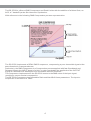
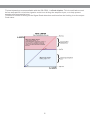
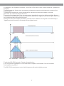
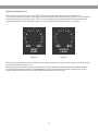
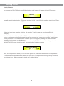
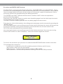
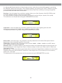
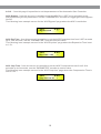
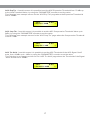
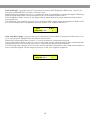
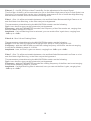
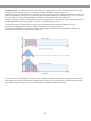
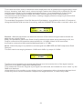
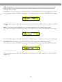
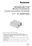
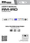
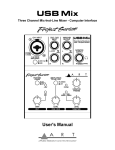
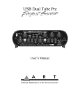
DS-CP22
USER’S MANUAL
PARAMETER
IN
DS-CP22
OUT
COMPRESSOR
ESCAPE
Dual Channel Compressor Limiter
19"
(482mm)
DIGITAL
USB
Contents
Introduction..........................................................................................1
Safety Instructions................................................................................ 2
Overview........................................................................................ 3 - 8
Getting Started with Front Panel Controls.................................... 9 - 24
Using the PC Interface.................................................................. 25 - 33
Input Meter Table......................................................................... 34 & 35
Comp/Limiter Activity Meter Table........................................................ 36
Block Scheme..................................................................................... 37
Specifications..................................................................................... 38
Introduction
Thank you for choosing a Galaxy DSPOT Digital Signal Processor. You have joined
hundreds of thousands of other satisfied Galaxy customers. Since 1977 Galaxy Audio’s
professional experience in design and manufacturing ensure our products' quality,
performance and reliability.
For the most up to date manual and information
visit www.galaxyaudio.com.
1
Safety Instructions
This symbol indicates that there are important
Operating and maintenance instructions in the
Literature Accompanying This Unit
This symbol indicates that dangerous voltage
Constituting a risk of electric shock is present
within this unit.
! IMPORTANT SAFETY INSTRUCTIONS !
1.
2.
3.
4.
5.
6.
7.
READ these instructions.
KEEP these instructions.
HEED all warnings.
FOLLOW all instructions.
DO NOT use this apparatus near water.
CLEAN ONLY with dry cloth.
DO NOT block any ventilation openings. Install in accordance with the manufacturer's instructions.
8. DO NOT install near any heat sources such as radiators, heat registers, stoves,
or other apparatus (including amplifiers) that produce heat.
9. DO NOT defeat the safety purpose of the polarized or grounding-type plug. A
polarized plug has two blades with one wider than the other. A grounding type
plug has two blades and a third grounding prong. The wider blade or the third
prong are provided for your safety. If the provided plug does not fit into your
outlet, consult an electrician for replacement of the obsolete outlet.
10. PROTECT the power cord from being walked on or pinched, particularly at plugs,
convenience receptacles, and the point where they exit from the apparatus.
11. ONLY USE attachments/accessories specified by the manufacturer.
12.
USE only with a cart, stand, tripod, bracket, or table
Specified by the manufacturer, or sold with the
Apparatus. When a cart is used, use caution when
moving the cart/apparatus combination to avoid
injury from tip-over.
13. UNPLUG this apparatus during lightning storms or when unused for long periods of
time.
14. REFER all servicing to qualified service personnel. Servicing is required when the
apparatus has been damaged in any way, such as power-supply cord or plug is damAged, liquid has been spilled or objects have fallen into the apparatus, the apparatus
has been exposed to rain or moisture, does not operate normally, or has been
dropped.
15. DO NOT expose the apparatus to dripping and splashing. DO NOT put objects filled
with liquids, such as vases, on the apparatus.
16. Remove the batteries from the receiver if the system will not be used for a long
period of time. This will avoid any damage resulting from a defective, leaking
battery.
17. DO NOT throw used batteries into a fire. Be sure to dispose of or recycle used
batteries in accordance with local waste disposal laws.
2
Overview
Below are the controls and functions of the front panel control buttons and encoders for the DS-CP22.
PARAMETER
IN
DS-CP22
OUT
COMPRESSOR
ESCAPE
1
2
3
5 6
4
7 8
9
1 - Input Level: Analog Input Gain Left/Right
2 - Button Compressor IN/OUT: RMS Compressor Active/Bypass
3 - Output Level: Analog Output Volume Left/Right
4 - LCD Display
5 - LED Clip: Input/Process Overflow
6 - Enc Parameter: Adjust Parameters Value
7 - Enter Key: Access to Editing Pages and Parameter Values Confirm
8 - Enter LED Indicator
9 - Enc Navigation: Compressor's Ratio and Knee selection
10 - Escape Key: Exit from Editing Pages
11 - Escape LED Indicator
12 - Power LED
13 - Power
3
10 11 12 13
The DS-CP22 is a Stereo RMS Compressor and Peak Limiter with the addition of a Noise Gate, an
AGC, a 7 bands Eq and a Sub Harmonic Synthesizer.
With reference to the following RMS Compression process representation:
The DS-CP22 implements a REAL RMS Compressor, compressing a pure sinusoidal signal at the
same threshold as a squared wave.
Particularly, the RMS Compressor is a Compression process applied with fast Slow Attack and
Release times to the INPUT signal of a Unit, in order to maintain the amplitude of the OUTPUT
signal at a defined level when input level exceeds a defined Threshold.
The Compressor implemented in the DS-CP22 reacts to the RMS value of the input signal,
resulting in a more musical compression.
The DS-CP22 Compressor has adjustable Ratio and Hard/Soft Knee parameters. The input to
output ratio is accurate to 0.1dBu.
4
The Hard Knee and Soft Knee allow for instant or gradual compression once threshold is reached.
Together with the RMS Compressor, the DS-CP22 also includes 2 very useful Dynamic Processes,
An Automatic Gain Controller (AGC) and a Peak limiter.
In order to understand the operation of the AGC, please refer to the following graphic:
The AGC is an Expansion/Compression process applied with fairly slow Attack and Release times
To the INPUT signal, in order to maintain the average amplitude of the OUTPUT signal at a defined
level, independently from the averaged amplitude of the input sources.
The AGC expands the signal when below the threshold setting, and compresses when above the
threshold setting.
The process uses RMS levels resulting in a more musical sounding process. The AGC process is
useful in maintaining a consistent output level.
The Speed and the amount of the Expansion can be defined through the “Exp Time” and
“Exp Ratio” parameters. The speed and the amount of the Compression can be defined through
the “Cmp Time” and “Cmp Ratio” parameters.
When the Signal coming out from the AGC process (Output), applied to the AGC input, is above the
“Exp Thr” and below the “Thr Hold”, it is expanded up to the max expansion coefficient defined by
the Exp Ratio.
When the Signal coming out from the AGC process (Output), applied to the AGC input, is above the
“Cmp Thr”, it is compressed up to the minimum compression coefficient defined by the
“Cmp Ratio”.
When the AGC output is comprised within the “Thr Hold” and the “Cmp Thr” Thresholds, no further
expansion or compression actions will be taken and the expansion/compression coefficient, will be
maintained with its current value.
If the averaged AGC output level is “entering” the signal “hold” area coming from the
expansion area, then the Coefficient computed by the AGC for multiplying the input level in order to
get the proper output signal, will be higher than one (if the “Exp Ratio” will be set at 1:2), and the
coefficient will be lower than one (if the “Cm Ratio” will be set between 2:1 and 16:1) if the
Averaged AGC output level is “entering” the signal “hold” area coming from the compression area.
5
The last dynamic process available with the DS-CP22, is a Peak Limiter. This is useful when used
before an amplifier to limit the signal to avoid over-driving the amplifier input, or to help protect
speakers from excessive level.
This kind of Limiter is acting on the Signal Peak detection and therefore the limiting is on the output
Peak value.
6
In addition to the Dynamic Processes, in the DP-CP22 there is also a Sub Harmonic Synthesizer
available.
The Sub Harmonic Synthesizer generates sub Harmonics based on the Harmonic content of the
original signal.
The amplitude distribution of the generated Sub Harmonics follows the shape of a band
pass filter set on the low part of the band.
The peak of this “band pass” filter, is centered on 2 possible frequencies, 60Hz and 90Hz. Setting
the filter peak at 60Hz (24-36Hz), the Harmonics added to the original sound will bring a “deep” and
very low extra body to the original sound.
Setting the filter peak at 90Hz (36-56Hz), the Harmonics added to the original sound will bring a
“lighter and more booming” extra body to the original sound.
Finally, the DS-CP22 includes 7 bands of equalization:
A 1st or 2nd Order Highpass, a 1st or 2nd Order Lowpass, and 5 bands of 1st or 2nd Order
Peaking/Shelving filters.
The DS-CP22 has a bypass control which bypasses the entire digital process.
7
Input and Output Level
The Input and Output levels of the DS-CP22 can be adjusted by Analog Potentiometers.
The potentiometers operate in the analog domain before the A/D converter (Input Level) and after
The D/A converter (Output Level). There is not an absolute and fixed relationship between the
Input and Output Levels and the levels in front of the A/D and after the D/A converters.
4
4.5
5
5.5
3.5
6
4
5
5.5
3.5
6.5
7
3
4.5
2.5
6
6.5
7
3
2.5
7.5
7.5
2
8
2
8
1.5
8.5
1.5
8.5
9
1
MIN
9
1
9.5
0.5
9.5
0.5
MIN
MAX
OUTPUT
LEVEL
MAX
INPUT
LEVEL
Figure A
Figure B
The figures A and B are show in detail the possible positions of the potentiometers controlling the
Analog Input and Output Level.
Referring then to the above precise divisions of the available range between the MIN and MAX
Position of the potentiometers, the Max Analog Input/Output levels can be understood, so the
proper setting for the best use of the RMS Compressor can be found.
8
Getting Started
Getting Started
As soon as the DS-CP22 is turned ON the device model name will appear in the LCD screen:
DS-CP22
Compressor Limiter
And after quickly showing the “Firmware Version X.XXX”, the LCD will show the “Input Level” Page.
The default level is indicated by graphic meters.
Input Level
A: ||||||||||
B: ||||||||||
When the Input Level reaches clipping, the symbol ”>” will appear (as on channel B in the
example).
From this initial condition, and if an RMS Compressor or a Peak Limiter (or both) are set to be
Active, their compression/limiting activity can be seen on the “Compressor Activity” and “Limiter
Activity” windows. This is accessible from the Input Level page by rotating the NAVIGATION
encoder clock/counter-clock wise once.
If from the Input level window, the user wants to see the RMS Compressor’s activity, rotate the
NAVIGATION Encoder clockwise twice, accessing the following screen:
A:
Compressor Activity
|||# B:
||||||#
Here, the compression activity is shown from right to left, indicating the amount of compression.
For the relationship between the bars in the Input Level, Compression/Limiting Activity windows,
Input signal level, and compression depth, refer to the tables.
9
Encoders and ENTER, QUIT buttons
The DS-CP22 is equipped with 2 Relative Encoders, “PARAMETERS” and “NAVIGATION”. These
Encoders are used to navigate the user interface and edit sections of the processor. They allow the
User to navigate within the screen for the selection of sub-menus, pages and parameters, and to
select the values to be assigned during the editing operations.
The “ENTER” and “QUIT” buttons allow the user to confirm or NOT confirm the operations
performed by the encoders.
Particularly, the “ENTER” button is used to enter the editing pages from the initial Input Level and
Compressor/Limiter Activity screens.
The “QUIT” button is used to get back from any editing page to those screens.
From any one of the Initial windows, the editing menus and pages can be accessed by pressing the
“ENTER” button.
Once leaving the Input Level and Compressor/Limiter Activity windows, the screen will show on the
top row, the currently running preset and name, and on the lower row, the sub-menu for the
DS-CP22 functions/parameters access and editing.
Once leaving the Input Level and Compressor/Limiter Activity windows, if the currently running
Preset is the number 16 called “DeepCmp”, the screen will then appear as follows:
Preset 16 DeepCmp
Load Preset
To access all sub-menus you just need to rotate the NAVIGATION Encoder counter-clock wise.
The available Sub-menus are:
˜Load Preset: Loading one of the 32 available presets (16 factory and 16 users)
˜Save Preset: Store up to 16 user presets
˜Utility Function: Communication Interface setting (USB or MIDI)
˜Edit Parameters: Access to the parameters’ editing of all the DS-CP22 processes
10
Load Preset - this page allows the Loading of a preset program from one of the 16 factory presets
(1-16) or from one of the 16 user presets:
Preset 16: DeepCmp
Load Preset
By pressing ENTER and rotating the “NAVIGATION” encoder, it is possible to scroll through all
current available user presets.
Load Preset
<Preset:21 AGC_Fat>
If the Preset 21 is chosen (AGC_Fat), then pressing the “ENTER” button, the current temporary
window will appear,
Wait : Loading . . . . . .
<Preset:21 AGC_Fat>
And the AGC_Fat preset number 21 will be loaded and the sub-menu page will go back to the
previous level, updated:
Preset 21: AGC_Fat
Load Preset
Save Preset: this page allows you to store a new preset, up to 16, in the DS-CP22’s memory from
location 17 up to location 32, skipping the locations 1 to 16 that are reserved to the Factory
presets:
Preset21: AGC_Fat
Save Preset
By pressing the ENTER button and rotating the “PARAMETERS” encoder, it is possible to scroll
through the previously saved presets and the available empty locations (identified by “Empty”).
If no user presets are stored, the “Save a Program” screen will show empty memory locations for
All 17-32 presets as shown in the example below for location 30:
Save Preset
<Preset:30 Empty >
11
When storing an edited configuration for the DS-CP22, select the location for a preset from the 16
available by using the “PARAMETER” encoder.
Once the desired location appears on the screen press ENTER again to reach the “Edit Name
Preset” page.
If the location number 30 is ok, in example, then the screen will be the following:
Edit Name Preset
30: _preset name
In this page, the User can enter a Preset Name (up to 16 Characters) by using the “PARAMETER”
Encoder to choose a character and the “NAVIGATION” encoder to move between the 16 available
Locations for the character’s positioning.
The current position of the cursor is shown by a “blinking underscore”.
To store the Preset Name press the “ENTER” button again.
The above action will take you to the “Enter to Save” page showing the selected location for the
preset and the final edited name, for example LightCmp:
[Enter] to Save
30: LightCmp
Pressing “ENTER” again, you will store the preset in the selected location with the chosen name
and the following transitory screen will appear on the LCD:
Wait : Saving . . . . . .
30: LightCmp
Once the preset is saved, the DS-CP22 will go back to the previous level.
Preset 30: LightCmp
Save Preset
12
Utility Function - this sub-menu allows you define the remote control interface [USB or MIDI] to be
used for controlling the DS-CP22:
Preset 30: LightCmp
Utility Function
From “Utility Function”, press “ENTER” to access the “Config Communication” page, to choose the
remote control protocol for the DS-CP22.
Utility Function
Config Communication
By pressing “ENTER” and then using the PARAMETER encoder, you can choose between the two
possible interfaces (USB or MIDI) for the DS-CP22.
A MIDI channel from 01 to 15 can be selected, or the USB interfaces
Config Communication
Device <MIDI Ch=12>
Once you have selected the desired interface, a double click on the “QUIT” button will return to the
original menu.
Note: The “QUIT” button, once pressed as many times as necessary, will return to the top LCD
Level, which is the one displaying the Input Level or the Compressor/Limiter Activity.
13
Edit Parameters - in this sub-menu, all the parameters related to the signal processes of the
DS-CP22 are available for editing.
Pressing the “ENTER” button, the processes can be accessed for editing.
With the “NAVIGATION” Encoder, all the processes can be scrolled through and from the
“Edit Parameters” Sub Menu, the DS-CP22 channel can be selected for editing by simply rotating
clock/counter-clock wise the “PARAMETERS” encoder.
Upon entering the Edit Parameter Sub Menu, the screen will show the following:
Ch.A
Edit Param
Routing
In the case above, the parameters edited are for Channel A (ChA). For editing Channel B (ChB),
rotate the PARAMETER encoder and the screen shows the following,
Ch.B
Edit Param
Routing
Indicating that the Parameters edited will refer to ChB .
It is also possible to select Ch. A+B, and in this case the edited parameters will be assigned with
the same value to Channel A and B.
In the Editing Parameters Sub-menu, the available processes are:
Routing: Assigns the processor to Channel A, B or A+B
Input Gain: Digital control of the Input level
Noise Gate
A.G.C.
Filter 1 – Filter 7: Eq. Filter 1 is selectable as 1st or 2nd Order high-pass or low shelving and
the filters from 2 to 7 as 1st or 2nd Order shelving or peaking
Sub Harmony: Sub Harmonic Synthesizer centered around 65Hz or 90Hz
Drive: Signal Control before the RMS Compressor
RMS Compressor
Volume: Make Up Volume after the RMS Compressor and before the Peak Limiter
Peak Limiter
Mute: Output Channel Muting.
14
In order to edit the parameters of any single process, enter the process editing page by pressing
the “ENTER” button and leaving it. Once finished editing, by pressing the “QUIT” button to go back
to the Editing Parameters sub-menu and select the new process to edit by scrolling through the
processes with the NAVIGATION encoder.
Routing - from this page it is possible to assign either one of the 2 inputs of the DS-CP22 to the
currently edited Channel’s processes and Output.
So, it is possible to assign to the processes of Channel A and its Output, Input A, B or (A+B).
The selection can be operated using the PARAMETER encoder.
Ch.A
<
Input A
Routing
>
Input Gain - from this page it is possible to adjust the Input Level digitally (after the A/D
converters) ranging from -12dBu up to +6dBu, by steps of 0.5dBu.
The adjustment can be operated using the PARAMETER encoder.
Ch.A
<
Input Gain
0.0dB
>
Noise Gate - from this page, it is possible to set the parameters of a Noise Gate placed at the
beginning of the all dynamic and Eq. Processes.
Threshold - the Noise Gate Threshold can be set as -80dBu, -85dBu, -90dBu or as OFF. When
OFF, the Noise Gate is just bypassed.
Release Time - it is the time taken to un-mute the output once detected again an input signal over
the set threshold. It can range from 5ms to 100ms, by steps of 1ms up to 10ms, and of 10ms from
10ms up to 100ms.
Attack Time - is the time taken by the Noise Gate to enter the Output Mute condition once the Input
Signal is detected to be below the Threshold. It can range from 0.5 seconds up to 2 seconds by
steps of 0.1 seconds.
The adjustment of the parameters can be operated using the PARAMETER encoder.
Ch.A
<
Noise Gate
Attack = 0.5s
>
15
A.G.C. - from this page it is possible to set the parameters of the Automatic Gain Controller.
AGC Bypass - from this screen it is possible to set the AGC On or OFF, so to activate it or not
without resetting the all parameters, use the “PARAMETER” encoder for toggling the AGC Bypass
On/Off.
The following is an example screen for the “AGC Bypass” page where the AGC is set Active:
Ch.A
< Bypass = ON
A.G.C.
>
AGC Exp Time - from this screen it is possible to set the AGC Expansion time from 0.057 seconds
up to 14.4 seconds, use the “PARAMETER” encoder to set the value.
The following is an example screen for the “AGC Exp time” page where the Expansion Time is set
to 1.5s:
Ch.A
A.G.C.
< Exp Time = 1.5s
>
AGC Cmp Time - from this screen it is possible to set the AGC Compression time from 0.014
seconds up to 6 seconds, use the “PARAMETER” encoder to set the value.
The following is an example screen for the “AGC Cmp time” page where the Compression Time is
Set to 0.5s:
Ch.A
A.G.C.
< Cmp Time = 0.5s
>
16
AGC Exp Thr - from this screen it is possible to set the AGC Expansion Threshold from -70 dBu up
to the Hold Threshold Value, by using the “PARAMETER” encoder to set the value.
The following is an example screen for the “AGC Exp Thr” page where the Expansion Threshold is
Set to -50dBu:
Ch.A
A.G.C.
< Exp Thr = -50dB
>
AGC Cmp Thr - from this screen it is possible to set the AGC Compression Threshold Value up to
0dBu, by using the “PARAMETER” encoder to set the value.
The following is an example screen for the “AGC Cmp Thr” page where the Compression Threshold
Is set to -3dBu:
Ch.A
A.G.C.
< Cmp Thr = -3dB
>
AGC Thr Hold - from this screen it is possible to set the AGC Threshold of the AGC Signal “Hold”
area, from -69 dBu up to -1dBu, by using the “PARAMETER” encoder to set the value.
The following is an example screen for the “AGC Thr Hold” page where the Threshold of the Signal
“Hold” area is set to -40dBu:
Ch.A
A.G.C.
< Thr Hold = -40dB
>
17
AGC Exp Ratio - from this screen it is possible to set the AGC Expansion Ratio from 1 up to 2, by
using the “PARAMETER” encoder to set the value.
When the Expansion Ratio is set to 1, actually there is no possibility to expand the signal. Meaning
that the signal amplitude can be multiplied for a coefficient not higher than 1.
If the Expansion Ratio is set to 2, the signal can be expanded up to a max amplitude that is twice
the original one.
The following is an example screen for the “AGC Exp Ratio” page where the Expansion Ratio is set
to 2 and the signal can be expanded up to the double of its original amplitude.
Ch.A
< Exp Rto = 1:2
A.G.C.
>
AGC Cmp Ratio page - from this screen it is possible to set the AGC Compression Ratio from 1 up
to 16, by using the “VARIATION” encoder to set the value.
When the Compression Ratio is set to 1, it not is possible to compress the signal.
If the Compression Ratio is set to 2 or more, the signal can be expanded up to a min amplitude that
is depending from the ratio and can reach 1/16th of the original signal amplitude.
The following is an example screen for the “AGC Cmp Ratio” page where the Compression Ratio is
Set to 4 and the Signal can be compressed up to 1/4th of its original amplitude
Ch.A
< Cmp Rto = 4:1
18
A.G.C.
>
Filters 1-7 - the DS-CP22 provides 7 bands Eq. for the adjustment of the Input Signal.
The first filter of the Eq. can be selected to be 1st or 2nd Order High-pass or a 1st or 2nd Order Low
Shelving. The seventh filter can be 1st or 2nd Order Low-pass or a 1st or 2nd Order High Shelving
and the filters from the 2nd to the sixth are Peaking filters.
Filter 1 - filter 1 is a filter selectable between a 1st and 2nd Order Butterworth High Pass or a 1st
and 2nd Order Low Shelving, or the filter can just be bypassed.
The parameters selectable using the NAVIGATION encoder are the following:
Type - here the filter type can be selected or just bypassed.
Frequency - with the PARAMETER encoder, the frequency of the filter can be set, ranging from
20Hz to 20kHz in steps of 1/12Oct.
Amplitude - if a Low Shelving filter is selected, you can set the filter’s gain here, ranging from
-6dBu up to +6dBu.
Filter 2-6 - filter 2-6 are Peaking filters.
The parameters selectable using the NAVIGATION encoder are the following:
Q-Type - here the filter’s Q can be set ranging from 0.05 up to 2.00 by steps of 0.05.
Frequency - with the VARIATION encoder the cutting frequency of the filter can be set ranging
from 20Hz to 20kHz by steps of 1/12Oct.
Amplitude - here, the filter’s gain can be set, ranging from -6dBu up to +6dBu.
Filter 7 - filter 7 is a filter selectable between a 1st and 2nd Order Butterworth Low Pass or a 1st
and 2nd Order High Shelving, or the filter can just be bypassed.
The parameters selectable using the NAVIGATION encoder are the following:
Type - here the filter type can be selected or just bypassed.
Frequency - with the PARAMETER encoder the cutting frequency of the filter can be set ranging
from 20Hz to 20kHz by steps of 1/12Oct.
Amplitude - if a High Shelving filter is selected, here you can set the filter’s gain, ranging from
-6dBu up to +6dBu.
19
Sub Harmonic - the Sub Harmonic Synthesizer is a particular process, already introduced in the
first part of the manual, that isn’t actually related to the RMS compression one.
The Sub Harmonic Synthesizer is intended to be an “extra” process available to the user, where the
RMS Compressor is chosen for processing a source addressed to a “background” use, as in clubs.
It is possible to have synthesized bass in order to extend the band. Also when the
musical program is poor of harmonics in the low frequencies, it can help in improving the quality of
the background music and to gain a "heavier" or more vibrant sound.
The Sub Harmonic Synthesizer is a process synthesizing the first lower harmonic of the
frequencies ranging from 40Hz to 500Hz, detected in the original signal.
This means that there in the original signal, are detected frequencies from 40Hz to 500Hz, sub
harmonics from 20Hz to 250Hz are generated.
Figure F
As can be seen in the Figure F, however, the synthesized sub harmonics are not generated in the
Low harmonics’ band with the same amplitude, but with a Peak on 65Hz or on 90Hz and then with
decreasing amplitude going up from 65Hz/90Hz to 250Hz and down to 20Hz.
20
This is due to the fact, that to extend the same amplitude to the all sub harmonics generated, would
bring a “booming” and “dark” result, where having a Peak on the 65Hz(24-36) or 90Hz(36-56), will
leave the max intensity of the synthesized sub harmonics, in correspondence of the original
fundamentals, ranging around 130Hz and 180Hz, where typically is the octave used by
instruments such as the Bass or Kick Drum, creating a bigger presence and giving the music that
much sought after “punch”.
The available Parameters of the Sub Harmonic Synthesizer, accessible by the Unit’s Front panel,
Using the NAVIGATION encoder for scrolling and the PARAMETER encoder to set their value, are:
Ch.A
< Freq =
36
Harmony
-56 Hz >
Percent - With this parameter can be set the amount of Sub Harmonics generated, that will be
added to the original Signal.
Freq - this parameter selects the Peak of the Synthesized sub band, when selecting 24-36, the
Peak is centered on 65Hz and the max amplitude is +18.6dBu. When 36-56 is selected,
the Peak is centered on 90Hz and the Max amplitude is 15.7dBu.
Drive - within this page it is possible to set the signal level BEFORE the RMS compressor Peak
Detector.
The Gain can be set ranging between -12dBu and +6dBu, by steps of 0.5dBu:
Ch.A
<
0.0dBu
Drive
>
The Drive is not increasing the actual Input Signal level, but just the drive of the signal used as
reference for the RMS Compressor RMS detector.
This means the Drive the Original Input Signal isn't affected, but instead the level “seen” by the
RMS level detector.
Using the drive, it is possible to get a higher level of compression without changing the input level.
In this way, the Drive can extend the compression range 6dB more, or reduce it by 12dB.
21
RMS Compressor - the RMS compressor parameters can be controlled by entering the editing
screens and scrolling the parameters with the NAVIGATION encoder and setting them with the
PARAMETER encoder:
Threshold - from this page it is possible to set the Threshold parameters of the RMS Compressor.
Once within the page, the RMS Compressor’s Threshold can be set by the PARAMETER encoder:
Ch.A
RMS Compr.
< Threshold = -10dB
>
The selectable range of the RMS Compressor’s Threshold is from 0dBu (OFF) to -24dBu in steps of
0.1dBu.
Ratio - from this page it is possible to set the Ratio parameters of the RMS Compressor.
Once within the page, the RMS Compressor’s Threshold can be set by the PARAMETER encoder:
Ch.A
RMS Compr.
< Ratio = 32:1
>
The selectable range of the RMS Compressor’s Ratio is from 1:1 (Off) up to 32:1 (Lim) in steps of 1.
H/S Knee - from this page it is possible to set the “Knee” type of the RMS Compressor.
Once within the page, the RMS Compressor’s Threshold can be set by the PARAMETER encoder:
Ch.A
RMS Compr.
< H/S Knee = 48%
>
The selectable range of the RMS Compressor’s Knee type is from 0% (Hard) up to 100% (Soft) by
Steps of 1%
22
Release - from this page it is possible to set the Release Time parameters of the RMS Compressor.
Once within the page, the RMS Compressor’s Threshold can be set by the PARAMETER encoder:
Ch.A
RMS Compr.
< Release = 1.1s
>
The selectable range of the RMS Compressor’s Release Time is from 0.1s to 5s in steps of 0.1s up
to 3s and 0.2 from 3s to 5s.
Attack - from this page it is possible to set the Attack Time parameters of the RMS Compressor.
Once within the page, the RMS Compressor's Threshold can be set by the PARAMETER encoder:
Ch.A
RMS Compr.
< Attack = 200ms
>
The selectable range of the RMS Compressor’s Attack Time is from 5ms to 200ms, in steps of 1ms
from 5ms to 20ms, in steps of 5ms from 20ms to 30ms, in steps of 10ms from 30ms to 100ms and in
steps of 20ms - from 100ms to 200ms.
Make Up - within this page, it is possible to set the signal level AFTER the RMS compressor to
make up the reduced level compressed signal, before the Peak Limiter.
The Gain can be set ranging between -12dBu and +12dBu, by steps of 0.5dBu:
Ch.A
<
3.0dBu
23
Volume
>
PEAK Limiter - the Peak Limiter parameters can be controlled by entering the editing screens and
scrolling the parameters with the NAVIGATION encoder and setting them with the PARAMETER
encoder.
Threshold - from this page it is possible to set the Threshold parameters of the Peak Limiter.
Once within the page, the Peak Limiter’s Threshold can be set by the PARAMETER encoder:
Ch.A
Peak Limiter
< Threshold = 200ms
>
The selectable range of the Peak Limiter’s Threshold is from 0dBu (OFF) to -24dBu in steps of
0.1dBu
Release - from this page it is possible to set the Release Time parameters of the Peak Limiter.
Once within the page, the Peak Limiter’s Threshold can be set by the PARAMETER encoder:
Ch.A
Peak Limiter
< Release = 1.1s
>
The selectable range of the Peak Limiter’s Release Time is from 0.1s to 5s in steps of 0.1s up to 3s
and 0.2 from 3s to 5s.
Attack - from this page it is possible to set the Attack Time parameters of the Peak Limiter.
Once within the page, the Peak Limiter’s Threshold can be set by the PARAMETER encoder:
Ch.A
Peak Limiter
< Attack = 200ms
>
The selectable range of the Peak Limiter’s Attack Time is from 5ms to 200ms, in steps of 1ms from
5ms to 20ms, in steps of 5ms from 20ms to 30ms, in steps of 10ms from 30ms to 100ms, and in
steps of 20ms - from 100ms to 200ms.
Mute - within this page is possible to mute and un-mute the output of the currently edited Channel.
Ch.A
<
OFF
24
Mute
>
Using the PC Interface
Using the DS-CP22 Software.
l
l
l
l
l
l
Load the Software “SetupDS-CP22V1.0.0” either with the included CD or via the Galaxy Website.
Double click on “Setup”, choose “Run” the software will load.
Go to programs and double click on DS-CP22V1.0.0
Connect the SDS-CP22 with the USB cable to your computer.
Turn on the DS-CP22, the driver software will load automatically.
When the driver has finished loading, click once on “connect”.
If you want to continue select “Yes”
Choose your connection type.
Then Click on Connect.
25
The software will look for active devices and show them in a list.
To edit Double click on the desired device in the ID list.
The Main Page will load.
26
The device will also be locked out from front panel control at this point.
You may choose to “Load Preset from PC”, “Save Preset to PC”, “Store Preset to Device”, “Read Preset
from Device”
You can name a device by selecting edit device name.
27
From the main page you can choose the section you want to adjust by clicking on the associated block.
Once you have accessed the block you can adjust parameters by either using the sliders, arrows, or typing
the values in directly.
Select the gain block to access the gain and polarity of the inputs.
28
Select the EQ block to access the filters.
29
Select the Compressor Block to access the Compressor page.
30
Select the Limiter Block to access the Limiter page.
Select the AGC Block to access the AGC page.
31
Select the Noise Gate Block to access the Noise Gate page.
Select the SUB-H Block to access the Sub harmonic generator page.
32
You can copy parameters between channels by selecting the copy channel block and then selecting the
source parameters and the destination.
33
Input Meter Table
In order to properly use the indication of the Input Level Meters, it is necessary to note that the
Input level to the DS-CP22 is not considered “absolute” information, due to the fact that before the
A/D converter, the absolute Input Level can be “adjusted” by the analog potentiometer “Input
Level”.
For this reason, the meters of the Input Level Display on the LCD are intended to show the Input
Signal Level detected by the DSP after the A/D conversion, considering as 0dBu the Maximum
Input accepted and converted by the A/D.
On the basis of the above, the following table provides the relationship between the Input Level
Meters and the Signal Level in the digital domain, before the DS-CP22 processes, assuming not
clipping the Signal after the A/D.
Therefore it is important, in order to have reasonable indications from the Input Level meters, to
ensure the Input signal isn’t clipped.
Remember that the Input Signal Clip is occurring when the Absolute Input Signal exceeds
+15dBu (Clip on the Op Amps before the A/D converter), or when the Red Clip LED is On.
Setting the DS-CP22 in a “0dBu Path” condition (see the introduction for the 0dBu Path
Definition/setting), the following table shows the relation between the Input Level Meters and the
absolute Input Level after the A/D converter and the before the DS-CP22 processes.
Refer to the following picture:
34
The following Table shows the relationship between the Input Level Meters and the absolute Input
Level after the A/D converter and the before the DS-CP22 processes.
Meter Bar
Input Level
Clip
>0dBu
18
0dBu (Red Clip LED)
17
-1dBu
16
-3dBu
15
-5dBu
14
-7dBu
13
-9dBu
12
-11dBu
11
-13dBu
10
-15dBu
9
-17dBu
8
-19dBu
7
-21dBu
6
-23dBu
5
-25dBu
4
-27dBu
3
-29dBu
2
-31dBu
1
-35dBu
35
Comp/Limiter Meter Table
The Compressor and Limiter Activity Meters provide information in the same manner as the Input
Meters.
The following table shows the relation between the Compressor/Limiter Activity bar meter and the
depth in dBu of the compression/Limiting action.
The displayed Compression/Limiting action is from top to down (in the LCD case, from right to left)
Indicating the “reduction” of level operated by the Compression/Limiting Actions.
Bar Meter
Compression/Limiting in dBu
No Activity
0dBu (No Compression/Limiting)
1
-1dBu
2
-3dBu
3
-6dBu
4
-8dBu
5
-10dBu
6
-12dBu
7
-14dBu
8
-16dBu
9
-18dBu
10
-20dBu
11
-22dBu
12
-24dBu
36
Block Scheme
DS-CP22 Processes Block Scheme
37
Specifications
Ÿ DS-CP22 Technical Specifications
FUSE: REPLACE WITH 800mA SAME TYPE FUSE
USB
Analog Inputs: Balanced 2 TRS/2 XLR
Analog Outputs: Balanced 2 TRS/2 XLR
Input Max Levels: +15dB u
Output Max Level: +10dBu
THD+N: <0.01% @ -6dBFS (Bypass)
S/N Ratio: >100dBu (Processes in Bypass)
Frequency Response: 20Hz – 20kHz +/-0.5dB
A/D and D/A Resolutio n: 24bit
Process Resolution : 24x48 bit
Processes: RMS Stereo Compressor
Power Supply: 110V/220V (Switchable)
2x20 characters LCD display for the Parameters Editing
Fully remotely controllable by USB or MIDI interfaces
Dimensions: 9.25" x 19" x 1.75" (234.95 x 482.6 x 44.45 mm)
Weight: 6.3lb (2.86kgs)
38
THREE YEAR LIMITED WARRANTY
WARRANTY Information can be viewed online at
http://www.galaxyaudio.com/warranty.php
DS-CP22
Specifications in this manual are subject to change without notice.
For the most up to date manual and information
visit www.galaxyaudio.com.
1-800-369-7768
www.galaxyaudio.com
© Copyright Galaxy Audio 2014
Printed in China
V02062014