1
kÉï=~ë=çÑW=
MRKOMMV
áåi~Ä
léÉê~íáåÖ=fåëíêìÅíáçåë
båÖäáëÜ
This product is covered by one or more of the following US patents:
• US6485305
• US6885464
• US7010150
• US6454629
• US6394880
• US6614538
• US6953383
• US6702649
• US7178731
• US7163443
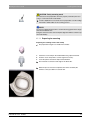
inLab
START
STOP
Sirona Dental Systems GmbH
Contents
Operating Instructions inLab
Contents
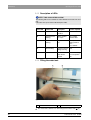
1
Dear Customer............................................................
6
2
General information ...................................................
7
2.1
2.1.1
2.2
2.3
2.3.1
Structure of the documents ..............................
Legend ..............................................................
Warranty ...........................................................
Disposal ............................................................
Additional note on disposal ...............................
7
7
8
8
8
General description....................................................
9
3.1
3.2
Certification ......................................................
Intended use .....................................................
9
9
Safety...........................................................................
10
3
4
4.1
4.1.1
4.1.2
4.1.3
4.1.4
4.2
4.2.1
4.2.2
4.3
4.4
5
59 07 568 D 3329
D 3329.201.02.17.02
05.2009
Basic safety information ...................................
10
Prerequisites .....................................................
10
Maintenance and repair.....................................
10
Modifications of the unit.....................................
10
Accessories .......................................................
10
Milling unit ........................................................
11
Safety information for the scanner ....................
11
Milling chamber door open during the milling operation
11
Wireless phone interference with equipment ....
12
Disturbance of data transmission via radio module
(option) .............................................................
12
Installation and startup ..............................................
13
5.1
5.2
5.3
5.3.1
5.4
5.4.1
5.4.2
5.4.3
5.4.4
5.4.5
5.4.6
5.5
13
13
13
14
14
14
15
16
16
17
20
24
Transport and unpacking ..................................
Disposal of packaging materials .......................
Installation site ..................................................
Installation site with low light incidence .............
Initial startup .....................................................
Controls and functional elements ......................
Information on the START/STOP button ...........
Description of LEDs...........................................
Filling the water tank .........................................
Installation .........................................................
Switching the units on .......................................
Repacking ........................................................
3
Sirona Dental Systems GmbH
Contents
Operating Instructions inLab
5.6
5.7
6
7
8
9
4
Scope of supply ................................................
Storage .............................................................
24
24
Operation ....................................................................
25
6.1
6.2
6.2.1
6.2.2
6.3
6.4
6.5
6.5.1
6.5.2
6.5.3
6.5.4
6.5.5
25
25
26
30
31
33
35
35
36
38
40
40
Setting the acquisition system to scanner ........
Calibrating the unit ...........................................
Calibrating the milling unit .................................
Calibrating the scanner .....................................
Starting the scanning process ..........................
Start the milling process ...................................
Preparing optical scanning ...............................
Information on preparing models for implants ...
Preparing for scanning of the crown stump.......
Preparing the Scanning of the Bridge Abutments
Preparing for scanning of the WaxUp model.....
Preparing for scanning of the veneer model .....
Maintenance................................................................
41
7.1
7.1.1
7.1.2
7.2
7.2.1
7.2.2
7.3
7.4
7.4.1
7.4.2
7.4.3
7.5
7.6
Changing the water ..........................................
General information...........................................
Changing the water ...........................................
Milling instruments ............................................
Overview of materials and milling instruments ..
Changing milling instruments (burs)..................
Care and cleaning agents ................................
Cleaning surfaces .............................................
Disinfecting........................................................
Protection against medicaments .......................
Cleaning ............................................................
Replacing the main fuses .................................
Removing water from the unit ..........................
41
41
42
44
44
45
47
47
47
47
47
48
49
Technical description ................................................
50
8.1
8.2
8.2.1
8.2.2
8.2.3
8.3
50
50
51
52
52
53
System requirements .......................................
Milling unit ........................................................
Technical data ...................................................
Scanner for optical measurement of the preparation
Controller board:................................................
Radio module (optional) ...................................
Appendix .....................................................................
54
59 07 568 D 3329
D 3329.201.02.17.02 05.2009
Sirona Dental Systems GmbH
Contents
Operating Instructions inLab
9.1
9.2
9.3
9.4
Procedure in case of problems downloading via the
DECT radio interface ........................................
54
Procedure in case of problems downloading via the
Höft&Wessel radio interface .............................
54
Procedure in case of problems downloading with the
supplied serial cable .........................................
55
Overview of old and new designations for milling
instruments .......................................................
55
Index.............................................................................
59 07 568 D 3329
D 3329.201.02.17.02
05.2009
56
5
1 Dear Customer
Sirona Dental Systems GmbH
Operating Instructions inLab
1
Dear Customer
Thank you for purchasing your inLab® from Sirona.
This device enables you to produce dental restorations, e.g. from ceramic
material with a natural appearance (CEramic REConstruction).
Improper use and handling can create hazards and cause damage. Please
read and follow these operating instructions carefully and always keep them
within easy reach.
To prevent personal injury or material damage it is important to observe all
safety information.
To safeguard your warranty claims, please complete the attached
Installation Report / Warranty Passport when the system is handed over
and send it to the indicated fax number.
Your
inLab Team
6
59 07 568 D 3329
D 3329.201.02.17.02 05.2009
2 General information
Sirona Dental Systems GmbH
Structure of the documents
Operating Instructions inLab
2
General information
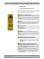
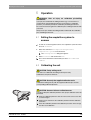
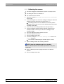
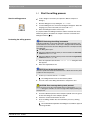
CAUTION: Be sure to observe all warnings!
Please observe the warning and safety information provided to prevent
personal injury and material damage. Any such information is highlighted by
a signal word, i.e. WARNING, CAUTION or NOTE.
Please read these operating instructions completely and follow them exactly.
always keep them within easy reach.
2.1
Structure of the documents
Structure of the documents
The symbols and character formats used in the present manual have the
following meaning:
WARNING:
Identifies warnings where a medium risk of injury to persons exists if they are
not observed.
CAUTION:
Identifies safety information where the following hazards exist if they are not
observed: Slight risk of injury to persons, risk of property damage or damage
to the product.
NOTE: Assistance
Identifies additional information, hints and tips.
9
Prerequisite
¾
Action
Requests you to do something.
or
¾
ª
1., 2., …
Result
See chapter on "General
information". [ 7]
Identifies a reference to another text
passage.
List
Identifies a list.
“Text between
quotation marks“
Identifies commands, menu items or
quotations.
2.1.1 Legend
Year of manufacture
59 07 568 D 3329
D 3329.201.02.17.02
05.2009
7
2 General information
Sirona Dental Systems GmbH
Warranty
Operating Instructions inLab
2.2
Warranty
To safeguard your warranty claims, please complete the attached Installation
Report / Warranty Passport when the system is handed over. Then fax it to
the specified fax no.
2.3
Disposal
Any disposal of this product must comply with the relevant national
regulations. Please observe the regulations applicable in your country.
Within the European Economic Community, Council Directive 2002/96/EC
(WEEE) requires environmentally sound recycling/disposal of electrical and
electronic devices.
Your product is marked with the adjacent symbol. Disposal of your product
with domestic refuse is not compatible with the objectives of environmentally
sound recycling/disposal. The black bar underneath the "garbage can"
symbol means that it was put into circulation after Aug. 13, 2005 (see EN
50419:2005).
Please note that this product is subject to Council Directive 2002/96/EC
(WEEE) and the applicable national law of your country and must be recycled
or disposed of in an environmentally sound manner.
Please contact your dealer if final disposal of your product is required.
2.3.1 Additional note on disposal
The system mainboard contains a lithium battery.
8
59 07 568 D 3329
D 3329.201.02.17.02 05.2009
3 General description
Sirona Dental Systems GmbH
Certification
Operating Instructions inLab
3
General description
3.1
Certification
CE mark
This product bears the CE mark in accordance with the provisions of Council
Directive 73/23/EEC 1 of February 19, 1973 concerning electrical equipment
designed for use within certain voltage limits.
CAUTION: CE mark for connected products
Further products which are connected to the milling unit must also bear the
CE mark. These products must be tested according to the applicable
standards.
Examples of CE mark for connected products:
z
EN 60601-1:1990 + A1:1993 +A2:1995 based on IEC 60601-1
z
EN 60950:1992 + A1: 1993 + A2: 1993 + A3: 1995 + A4: 1997 based on
IEC 60950
z
UL 60950 third edition 2000
3.2
Intended use
This unit produces computer-aided dental restorations, e.g. from naturalappearing ceramic material. It must not be used for any other purpose.
The intended use also includes observance of the present operating
instructions and the relevant maintenance instructions.
NOTE:
If the instructions for operation of the system described in this document are
not observed, the intended safety of the user may be impaired.
1. Amended by Council Directive 93/68/EEC.
59 07 568 D 3329
D 3329.201.02.17.02
05.2009
9
4 Safety
Sirona Dental Systems GmbH
Basic safety information
Operating Instructions inLab
4
Safety
4.1
Basic safety information
4.1.1 Prerequisites
NOTE: Important info on Building installation
The building installation must be performed by a qualified expert in
compliance with the national regulations. DIN VDE 0100-710 applies in
Germany.
NOTE: Restrictions regarding installation site
The system is not intended for operation in areas subject to explosion
hazards.
ATTENTION: Do not damage the unit!
The unit can be damaged if opened improperly.
It is expressly prohibited to open the unit with tools!
4.1.2 Maintenance and repair
As manufacturers of dental instruments and laboratory equipment, we can
assume responsibility for the safety properties of the unit only if the following
points are observed:
z
The maintenance and repair of this unit may be performed only by Sirona
or by agencies authorized by Sirona.
z
Components which have failed and influence the safety of the unit must be
replaced with original (OEM) spare parts.
Please request a certificate whenever you have such work performed. It
should include:
z
The type and scope of work.
z
Any changes made in the rated parameters or working range.
z
Date, name of company and signature.
4.1.3 Modifications of the unit
Modifications to this unit which may affect the safety of the operator, patients
or third parties are prohibited by law!
4.1.4 Accessories
To ensure product safety, this product may be operated only with original
Sirona accessories or third-party accessories expressly approved by Sirona.
The user assumes the risk of using non-approved accessories.
10
59 07 568 D 3329
D 3329.201.02.17.02 05.2009
4 Safety
Sirona Dental Systems GmbH
Milling unit
Operating Instructions inLab
4.2
Milling unit
4.2.1 Safety information for the scanner
Safety information for the scanner
This milling unit complies with Laser Class 1. It poses no hazard whatsoever.
The Laser itself is a Class 2 laser device and can injure a person's skin or
eyes. It is located on the left motor mount in the scanner.
WARNING: Laser radiation hazard
Gazing into the beam beam for longer periods of time can damage a person's
vision.
Never look directly into the laser beam and do not use any optical devices for
this purpose.
The laser beam emerges at right angles to the window of the scanner.
CAUTION:
Use of controls or adjustments or performance of procedures other than
those specified herein may result in hazardous radiation exposure.
NOTE: Laser beam
Power: < 1mW
Wavelength: 670 nm
Aperture angle: > 10 mrad
WARNING:
Check the scanner for visible signs of damage before each scanning
operation.
Check the door of the milling chamber for visible signs of damage before
each milling operation.
WARNING: Installing and removing the scanner
Only service engineers may install or remove the scanner.
4.2.2 Milling chamber door open during the milling
operation
WARNING: Milling instruments that continue to run
When the milling chamber door is opened during the milling operation, the
milling instruments could continue to run for a short time.
59 07 568 D 3329
D 3329.201.02.17.02
05.2009
¾
Be careful not to touch the milling instruments with your hand or any
other object during this time.
¾
Avoid opening the milling chamber door while the milling unit is in
operation.
¾
Before you open the milling chamber door, end any actions that are
running by selecting the "Stop" key on the milling unit or in the
application software.
11
4 Safety
Sirona Dental Systems GmbH
Wireless phone interference with equipment
Operating Instructions inLab
4.3
Wireless phone interference with
equipment
The use of mobile wireless phones in practice or hospital environments must
be prohibited to ensure safe operation of the unit.
4.4
Disturbance of data transmission via
radio module (option)
DECT radio module
Data transmission may be adversely affected in the following cases:
z
if more than 6 pairs of radio interfaces are used in one area
z
if an E-net mobile phone is used near the radio interface
Höft&Wessel radio module
Data transmission may be adversely affected if more than 8 pairs of radio
interfaces are used in one area.
If the radio module is operated in Norway, please note that it must not be
operated within a radius of 20 km around Ny-Alesund.
12
59 07 568 D 3329
D 3329.201.02.17.02 05.2009
Sirona Dental Systems GmbH
5 Installation and startup
Operating Instructions inLab
Transport and unpacking
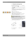
5
Installation and startup
5.1
Transport and unpacking
Transport and unpacking
All products from Sirona are carefully checked prior to shipment. Please
perform the incoming inspection immediately after delivery.
1.
Check the delivery note to ensure that the consignment is complete.
2.
Check whether the product shows any visible signs of damage.
NOTE: Damage during transport
If the product was damaged during transport, please contact your carrying
agent.
If return shipment is required, please use the original packaging for shipment.
Before every transport, the unit must be drained prior to shipment (if it has
been operated). See "Removing water from the unit" [ 49]
5.2
Disposal of packaging materials
The packaging must be disposed of in compliance with the relevant national
regulations. Please observe the regulations applicable in your country.
5.3
Installation site
WARNING: Install out of the reach of patients!
Do not install or operate the milling unit in the vicinity of the patient (place it at
least 1.5 m away from the patient).
The milling unit requires a level Approx. footprint: 480 x 440 mm (W x D). The
height of the milling unit is 250 mm:
Install the milling unit in such a way that it is not difficult to operate the main
switch.
Make sure that the ventilation slots underneath and at the back of the unit
remain unobstructed. The distance between the rear side of the unit and the
room wall must be at least 10 cm.
Note that the unit weighs 30 kg!
The unit must not be installed at sites with a high level of humidity or dust!
CAUTION: Installation in a cabinet
If the unit is installed in a cabinet, you must provide for adequate heat
exchange.
The ambient temperature surrounding the unit must be between 5°C and
40°C.
59 07 568 D 3329
D 3329.201.02.17.02
05.2009
13
5 Installation and startup
Sirona Dental Systems GmbH
Initial startup
Operating Instructions inLab
5.3.1 Installation site with low light incidence
Impairment of the scanned result
CAUTION: Impairment of the scanned result due to sudden
incidence of light.
A sudden, strong incidence of light may falsify the scanned result.
Set the unit up so that the milling chamber is not located directly in the beam
path of an extreme light source and is not exposed to direct sunlight.
5.4
Initial startup
CAUTION: Important information on initial startup
Observe the software installation instructions!
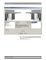
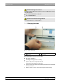
5.4.1 Controls and functional elements
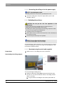
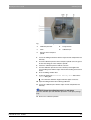
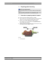
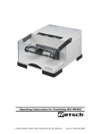
Overview of the front panel
Fig. 5-1 Front panel
14
A
Milling chamber
D
START button
B
Milling chamber
door catch
E
STOP button
C
LEDs
F
Front flap
59 07 568 D 3329
D 3329.201.02.17.02 05.2009
5 Installation and startup
Sirona Dental Systems GmbH
Initial startup
Operating Instructions inLab
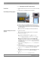
Ports on the back side
Ports on the back side
Fig. 5-2 Rear side
A
Fuse cover
C
Power connection
B
Main switch
I = ON, 0 = OFF
D
Serial port
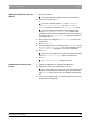
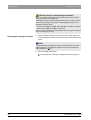
5.4.2 Information on the START/STOP button
START button
Fig. 5-3 START button
A
Button on the screen
B
START button on the milling unit
You can confirm all dialog boxes either by clicking the SW button Start on the
screen or by pressing the HW START button on the milling unit.
STOP button
Fig. 5-4 STOP button
A
Button on the screen
B
STOP button on the milling unit
A machining operation can be interrupted either by clicking on the SW Stop
button on the screen or by pressing the HW STOP button on the milling unit.
59 07 568 D 3329
D 3329.201.02.17.02
05.2009
15
5 Installation and startup
Sirona Dental Systems GmbH
Initial startup
Operating Instructions inLab
5.4.3 Description of LEDs
NOTE: Table also available as label
The following table is also available as a label affixed to the inside of the front
flap.
It describes the system states indicated by the LEDs.
Green LED
Yellow LED
Description
Actions required
ON
OFF
Ready for
operation
-
ON
Intermittent fast
flashing
Milling chamber
door open
Close milling
chamber door
ON
Intermittent slow
flashing
Request to insert
part
Insert part, close
milling chamber
door,
press START
ON
Slow flashing
Just before end of
milling/scanning
Wait
ON
ON
Error,
STOP button
pressed
Observe message
to PC/acquisition
unit
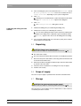
5.4.4 Filling the water tank
Water tank, inLab/CEREC 3
Fig. 5-5 2 liter water tank
A
9
16
Tank catch
B
Water tank
The water tank is drained, see "Removing water from the unit“ [ 49].
59 07 568 D 3329
D 3329.201.02.17.02 05.2009
5 Installation and startup
Sirona Dental Systems GmbH
Initial startup
Operating Instructions inLab
1.
Open the flap on the front panel of the unit. To open the front flap, pull it on
both sides.
2.
Press the tank catch upward and carefully pull out the water tank toward
the front of the unit.
3.
Open the water tank.
4.
Take the accessories out of the tank and remove the transport lock of the
water filter.
CAUTION: Damage to surfaces!
DENTATEC milling additive etches plastic surfaces in undiluted form and can
cause discoloration.
¾
Do not place DENTATEC on the unit.
¾
Do not spill DENTATEC.
5.
Add approx. 50 ml* of DENTATEC to the tank.
or
¾ * With the materials IVOCLAR VIVADENT IPS Empress CAD and
IVOCLAR VIVADENT IPS e.max CAD, approx. 75 ml.
NOTE: Recommended mixing ratio:
25ml of DENTATEC with 1l of water.
Deviations are possible for certain materials:
¾
With IVOCLAR VIVADENT IPS Empress CAD and IVOCLAR
VIVADENT IPS e.max CAD, mix approx. 37.5ml with 1l of water.
¾
With CAD-Waxx, mix approx. 5ml with 1l of water. See also the operating
instructions for the corresponding material.
6.
Fill the tank up to the notch with water (bottom edge of cover; approx. 2
liters).
7.
Reinsert the water filter and close the water tank.
8.
Push the water tank back into the housing just far enough so that the tank
catch engages (press the catch downward if necessary).
5.4.5 Installation
5.4.5.1 Connection to the PC
WARNING: Electric shock
Low voltages are applied to the socket (A) for connecting the serial interface.
¾
Never touch the pins of the connectors.
¾
Switch the PC OFF.
Using the RS 232 interface cable
59 07 568 D 3329
D 3329.201.02.17.02
05.2009
9
The PC is located near the milling unit.
9
The PC and the milling unit are switched off.
17
5 Installation and startup
Sirona Dental Systems GmbH
Initial startup
Operating Instructions inLab
Fig. 5-6 Connecting the milling unit with the interface cable
1.
Use the supplied interface cable to connect the milling unit to the RS 232
interface of the PC (COM1, COM2).
2.
Screw the interface cable onto the PC and milling unit tight in order to
ensure reliable operation.
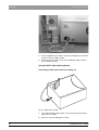
Using the DECT radio module (optional)
Connecting the DECT radio module to the milling unit
Fig. 5-7 DECT radio module
18
1.
If you ordered a DECT radio module, connect it instead of the interface
cable and screw it tight.
2.
Place it on top of the milling unit as shown.
59 07 568 D 3329
D 3329.201.02.17.02 05.2009
5 Installation and startup
Sirona Dental Systems GmbH
Initial startup
Operating Instructions inLab
Connecting the DECT radio module to the PC
1.
Plug the connectors of the RS-232 cable into the radio module and into
the RS-232 interface of the PC (COM1, COM2) and screw them tight.
2.
Connect the radio module to the power supply using the supplied plug-in
power supply unit.
Using the Höft&Wessel radio module (optional)
Connecting the Höft&Wessel radio module to the milling unit
Milling Unit “PT”
Fig. 5-8 Höft&Wessel radio module for milling unit
1.
If you ordered a Höft&Wessel radio module, connect it (with the label
Milling Unit "PT“) instead of the interface cable and screw it tight.
2.
Place it on top of the milling unit as shown.
Connecting the Höft&Wessel radio module to the PC
B
A
Acquisition Unit “FT”
Fig. 5-9 Höft&Wessel radio module for PC
59 07 568 D 3329
D 3329.201.02.17.02
05.2009
1.
Plug the connectors of the RS-232 cable into socket A of the radio module
labeled Acquisition Unit "FT" and into the RS-232 interface of the PC
(COM1, COM2) and screw them tight.
2.
Connect radio module B to the power supply using the supplied plug-in
power supply unit.
19
5 Installation and startup
Sirona Dental Systems GmbH
Initial startup
Operating Instructions inLab
5.4.5.2 Connecting the milling unit to the power supply
NOTE: Grounded power outlet
The milling unit must be connected to a grounded power outlet.
¾
Connect the milling unit to the power supply with the power cable
included in delivery.
5.4.6 Switching the units on
Note on condensate
CAUTION: Do not put the unit into operation at low
temperatures!
If you move the unit to the operating site from a cold environment,
condensation may form and result in a short circuit.
The millling unit contains grease depots for lubricating components which
can cause error messages at low temperatures.
9 Install the unit at room temperature.
¾
Wait until the unit has reached room temperature and is absolutely dry
(for at least one hour)
ª
The unit is dry and can be put into operation.
Line voltage
NOTE: Do not adjust the line voltage
The unit automatically adjusts to the line voltage.
The following three chapters describe how to download the latest software
version to the milling unit. Observe the chapter corresponding to the data
transmission hardware installed.
5.4.6.1 Download using the serial cable supplied
Preparations
¾
Switch on the PC. The milling unit must be switched off.
Performing a download, Hu.W, cable, new
Downloading the milling program
Fig. 5-10 Switching the milling unit on
¾
Switch the milling unit on (B), while keeping the download key (A)
pressed. You can release the Download key on the milling unit after
approx. 5 seconds.
ª The green LED on the milling unit is lit and the yellow LED is off.
20
59 07 568 D 3329
D 3329.201.02.17.02 05.2009
5 Installation and startup
Sirona Dental Systems GmbH
Initial startup
Operating Instructions inLab
Add device, DECT, HuW, cable, NEW
Adding the milling unit in the user
software
1.
Start the user software
ª
2.
A message stating that no milling machines are set up appears.
Confirm this message with "Yes".
or
¾ If you have accidentally clicked "No", select "Settings" /
"Configuration" / "Devices...", go to the "Configure
Devices" dialog box and click the "Add automatically" button.
ª The connected milling unit will automatically be detected. The
message "Downloading software to COMx" (COM1, COM2, ... –
depending on which interface the milling unit is connected to) appears in
the status bar of the "Configure Devices" dialog box. Wait until the
status display goes out.
3.
Enter a name for this milling unit ("Milling unit" is offered as the
default name).
4.
Click "Add Device".
5.
In the next dialog box, place a checkmark in front of "Scanner", in front
of "inLab gearhead installed" and, if one is installed, in front of
"Large watertank", depending on your system configuration.
6.
Click "OK".
ª Following a successful download, a yellow exclamation mark and the
message "No calibration data" appear in the dialog box.
7.
Click "OK".
ª
The "Configure Devices" dialog box is closed.
Calibrating inLab
Calibrating the milling unit and
scanner
1.
Calibrate the milling unit (see "Calibrating the milling unit").
2.
Calibrate the scanner (see "Calibrating the scanner").
ª As soon as the milling unit and the scanner have been calibrated, the
installation of the milling unit is completed. A green checkmark and the
status "Ready" appear next to the icon for the milling unit in the dialog
box.
3.
59 07 568 D 3329
D 3329.201.02.17.02
05.2009
If you encounter problems with one of the above points, please observe
the information in the appendix.
21
5 Installation and startup
Sirona Dental Systems GmbH
Initial startup
Operating Instructions inLab
5.4.6.2 Download via the DECT radio interface
Preparations
Preparations
1.
For this installation step, place your PC as close as possible to the milling
unit.
2.
Switch on the PC. The milling unit must be switched off.
Performing a download, DECT, new
Downloading the milling program
Fig. 5-11 Switching the milling unit on (DECT)
¾
Switch the milling unit on (B), while keeping the download key (A)
pressed. Wait until the left operating indicator (C) of the radio interface on
the milling unit lights up continuously. You can now release the Download
key on the milling unit.
ª The green LED on the milling unit is lit and the yellow LED is off.
Add device, DECT, HuW, cable, NEW
Adding the milling unit in the user
software
1.
Start the user software
ª A message stating that no milling machines are set up appears.
2.
Confirm this message with "Yes".
or
¾ If you have accidentally clicked "No", select "Settings" /
"Configuration" / "Devices...", go to the "Configure
Devices" dialog box and click the "Add automatically" button.
ª The connected milling unit will automatically be detected. The
message "Downloading software to COMx" (COM1, COM2, ... –
depending on which interface the milling unit is connected to) appears in
the status bar of the "Configure Devices" dialog box. Wait until the
status display goes out.
3.
Enter a name for this milling unit ("Milling unit" is offered as the
default name).
4.
Click "Add Device".
5.
In the next dialog box, place a checkmark in front of "Scanner", in front
of "inLab gearhead installed" and, if one is installed, in front of
"Large watertank", depending on your system configuration.
6.
Click "OK".
ª Following a successful download, a yellow exclamation mark and the
message "No calibration data" appear in the dialog box.
7.
Click "OK".
ª The "Configure Devices" dialog box is closed.
22
59 07 568 D 3329
D 3329.201.02.17.02 05.2009
5 Installation and startup
Sirona Dental Systems GmbH
Initial startup
Operating Instructions inLab
Calibrating inLab
Calibrating the milling unit and
scanner
1.
Calibrate the milling unit (see "Calibrating the milling unit").
2.
Calibrate the scanner (see "Calibrating the scanner").
ª As soon as the milling unit and the scanner have been calibrated, the
installation of the milling unit is completed. A green checkmark and the
status "Ready" appear next to the icon for the milling unit in the dialog
box.
3.
If you encounter problems with one of the above points, please observe
the information in the appendix.
5.4.6.3 Download via the Höft&Wessel radio interface
Preparations
Preparations
1.
For this installation step, place your PC as close as possible to the milling
unit.
2.
Switch on the PC. The milling unit must be switched off.
Performing a download, Hu.W, cable, new
Downloading the milling program
Fig. 5-12 Switching the milling unit on
¾
Switch the milling unit on (B), while keeping the download key (A)
pressed. You can release the Download key on the milling unit after
approx. 5 seconds.
ª
The green LED on the milling unit is lit and the yellow LED is off.
Add device, DECT, HuW, cable, NEW
Adding the milling unit in the user
software
1.
Start the user software
ª
2.
A message stating that no milling machines are set up appears.
Confirm this message with "Yes".
or
¾ If you have accidentally clicked "No", select "Settings" /
"Configuration" / "Devices...", go to the "Configure
Devices" dialog box and click the "Add automatically" button.
ª The connected milling unit will automatically be detected. The
message "Downloading software to COMx" (COM1, COM2, ... –
depending on which interface the milling unit is connected to) appears in
the status bar of the "Configure Devices" dialog box. Wait until the
status display goes out.
59 07 568 D 3329
D 3329.201.02.17.02
05.2009
3.
Enter a name for this milling unit ("Milling unit" is offered as the
default name).
4.
Click "Add Device".
23
5 Installation and startup
Sirona Dental Systems GmbH
Repacking
Operating Instructions inLab
5.
In the next dialog box, place a checkmark in front of "Scanner", in front
of "inLab gearhead installed" and, if one is installed, in front of
"Large watertank", depending on your system configuration.
6.
Click "OK".
ª Following a successful download, a yellow exclamation mark and the
message "No calibration data" appear in the dialog box.
7.
Click "OK".
ª The "Configure Devices" dialog box is closed.
Calibrating inLab
Calibrating the milling unit and
scanner
1.
Calibrate the milling unit (see "Calibrating the milling unit").
2.
Calibrate the scanner (see "Calibrating the scanner").
ª As soon as the milling unit and the scanner have been calibrated, the
installation of the milling unit is completed. A green checkmark and the
status "Ready" appear next to the icon for the milling unit in the dialog
box.
3.
5.5
If you encounter problems with one of the above points, please observe
the information in the appendix.
Repacking
CAUTION: Repack only drained units!
Drain the unit! See chapter on "Removing water from the unit". [ 49]
9
The water tank is empty.
9
The main switch on the back side of the unit is set to the 0 (OFF) position.
1.
Disconnect the power cable and the connecting cable from the back side
of the unit and stow them away.
2.
Stow away the block changing tool and the torque wrench in their holders
(to the left of the water tank).
3.
Check the unit for completeness according to the scope of supply!
4.
Pack the unit securely.
5.6
Scope of supply
The exact scope of supply is specified in the document "Checklist inLab".
5.7
Storage
CAUTION: Only drained units may be stored!
Drain the unit! See chapter on "Removing water from the unit". [ 49]
Store the unit in a closed and dry room at a temperature of -10°C to 50°C for
a maximum period of 12 months.
24
59 07 568 D 3329
D 3329.201.02.17.02 05.2009
6 Operation
Sirona Dental Systems GmbH
Setting the acquisition system to scanner
Operating Instructions inLab
6
Operation
WARNING: Risk of injury on calibration pins/milling
instruments
If you put your hand inside the milling chamber (e.g. to insert/remove a
ceramic block, change milling instruments, insert/remove a calibration
phantom), it could be injured by the calibration pins/milling instruments.
Be careful not to brush against the calibration pins or milling instruments with
your hand.
Always insert your hand in the milling chamber underneath the calibration
pins and milling instruments.
6.1
Setting the acquisition system to
scanner
Setting the acquisition system to scanner
9
In order to use the integrated scanner, the acquisition system first must
be set to "Scanner".
1.
Select the command "Settings" / "Configuration" /
"Acquisition system" in the menu line.
ª
The "Configuration" dialog box appears.
2.
Select "Scanner" and confirm with "OK".
ª
The scanner will remain selected until you select "3D camera" or
"inEos".
6.2
Calibrating the unit
CAUTION: Faulty milling result
If the unit is not calibrated, the milling result may be faulty.
Calibrate the unit prior to initial use
Calibration tools
CAUTION: Use only the supplied calibration tools
Calibrate the milling unit only with the supplied calibration pins and the
corresponding calibration phantom.
Keeping the calibration phantom clean, inLab/CEREC 3
CAUTION: Scanner failure or calibration error
If you do not keep the calibration phantom clean, proper calibration cannot be
performed.
59 07 568 D 3329
D 3329.201.02.17.02
05.2009
¾
Keep the calibration phantom clean; do not touch its sensor area with
your bare fingers.
¾
Always insert and remove the calibration phantom with the calibration
protection.
¾
Place the calibration phantom with calibration protection in the storage
box after each calibration.
25
6 Operation
Sirona Dental Systems GmbH
Calibrating the unit
Operating Instructions inLab
6.2.1 Calibrating the milling unit
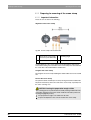
Performing calibration
Performing calibration
Fig. 6-1 Tools
A
Block changing tool
B
Torque wrench
9
The block changing tool, torque wrench and calibration phantom are
ready-to-hand.
9
The milling unit and PC are switched on.
9
The software has been started.
1.
Select the command "Settings" / "Calibration" / "Milling
unit" in the menu line.
2.
If several milling units are connected, a dialog box will appear. Select the
language you prefer and confirm your choice with "OK".
ª The milling unit then moves into position to insert the calibration tools.
A dialog box prompts you to insert the calibration pins and the calibration
phantom and to close the milling chamber door again.
3.
26
Press the catch of the milling chamber door and open the door.
59 07 568 D 3329
D 3329.201.02.17.02 05.2009
6 Operation
Sirona Dental Systems GmbH
Calibrating the unit
Operating Instructions inLab
Fig. 6-2 Calibrate the milling unit
A
Calibration phantom
B
Torque wrench
C
Catch
D
Calibration pin
E
Setscrew in the workpiece
spindle
4.
Loosen the milling instruments with the torque wrench and pull them out
manually.
5.
Insert the calibration phantom in the workpiece spindle so that its groove
fits into the locking pin of the workpiece spindle.
6.
Fasten the calibration phantom with the setscrew.
7.
Turn the calibration pins into the motor mount by hand. Tighten the
corresponding chuck with the torque wrench until a clicking sound can be
heard.
8.
Close the milling chamber door.
9.
Confirm by clicking the "Calibrate milling unit" button in the
"Start" dialog box.
ª
The automatic calibration begins and takes approx. 4 minutes.
10. Open the milling chamber door following calibration.
11. Loosen the calibration pins with the torque wrench and pull them out
manually.
NOTE: Store the calibration tools in a safe place
Store the calibration pins and calibration phantom in a safe place (storage
box).
12. Remove the calibration phantom.
59 07 568 D 3329
D 3329.201.02.17.02
05.2009
27
6 Operation
Sirona Dental Systems GmbH
Calibrating the unit
Operating Instructions inLab
Suitable milling instruments for inLab
CAUTION: Use only suitable milling instruments!
Do not use CEREC 2 milling instruments with chuck (1.2 mm) or 2.0 mm
milling instruments in this milling unit.
The Step Bur 14 and Cone Bur 14 milling instruments are used in connection
with the inLab gearing (serial number 11 200 and higher) to process the
following asymmetric blocks:
– VITA In-Ceram 2000 YZ CUBES: YZ-55 (Flip Block), YZ-20/19, YZ-40/19
– VITA In-Ceram 2000 AL CUBES: AL-20, AL-40
Any use of other materials may result in failures when creating the restoration
and cause damage to the unit.
Reinserting the milling instruments
1.
Insert the milling instruments in the motor mount by hand. Tighten the
corresponding chuck with the torque wrench until a clicking sound can be
heard.
NOTE:
A synoptical table of the milling instruments and the materials that can be
milled using them is provided in the Chapter "Overview of materials and
milling instruments" [ 44].
2.
Close the milling chamber door.
ª The dialog box for selecting the milling instruments then appears.
28
59 07 568 D 3329
D 3329.201.02.17.02 05.2009
6 Operation
Sirona Dental Systems GmbH
Calibrating the unit
Operating Instructions inLab
Fig. 6-3 Selecting the milling instruments following calibration
59 07 568 D 3329
D 3329.201.02.17.02
05.2009
3.
Select the milling instrument that you inserted in the left gearing from
the "Left" list and the milling instrument that you inserted in the
right gearing from the"Right" list.
4.
Confirm this procedure with "Start"
29
6 Operation
Sirona Dental Systems GmbH
Calibrating the unit
Operating Instructions inLab
6.2.2 Calibrating the scanner
Calibrating the inLab_CEREC3 scanner
9
The block changing tool and calibration phantom are ready-to-hand.
9
The milling unit and PC are switched on.
9
The software has been started.
1.
Select the command "Settings" / "Calibration" / "Scanner" in
the menu line.
2.
If several milling units are connected, a dialog box will appear. Select the
language you prefer and confirm your choice with "OK".
ª The milling unit moves into the calibration tool insertion position.
A dialog box then prompts you to insert the calibration phantom and close
the milling chamber door.
3.
Press the catch of the milling chamber door and open the door.
4.
Insert the calibration phantom with the calibration protection in the
workpiece spindle so that its groove fits into the locking pin of the
workpiece spindle.
5.
Fasten the calibration phantom with the setscrew.
6.
Pull off the calibration protection.
7.
Close the milling chamber door.
8.
Confirm by clicking the "Calibrate milling unit" button in the
"Start" dialog box.
ª The automatic calibration begins and takes approx. 1 minute.
9.
Open the milling chamber door following calibration.
NOTE: Store the calibration tools in a safe place
Store the calibration phantom with calibration protection in a safe place
(storage box).
10. Set the calibration protection upright and remove the calibration
phantom.
11. Close the milling chamber door.
30
59 07 568 D 3329
D 3329.201.02.17.02 05.2009
6 Operation
Sirona Dental Systems GmbH
Starting the scanning process
Operating Instructions inLab
6.3
Starting the scanning process
Starting the scanning process
9
The acquisition system must be set to "Scanner", see "Setting the
acquisition system to scanner". [ 25]
1.
Prepare the model holder as described in the chapter "Preparing optical
scanning“ [ 35].
2.
Create a new restoration (see user's manual, chapter on "Creating a new
restoration").
3.
If several milling units are connected, a dialog box will appear. Select the
language you prefer and confirm your choice with "OK".
4.
Click the acquisition icon.
ª
5.
The "Scanner" dialog box opens.
The milling unit then moves to the insertion position.
ª A new dialog box then appears prompting you to insert a model
holder and close the milling chamber door.
6.
Press the catch of the milling chamber door and open the door.
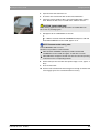
WARNING: Sharp edges on scanner!
The scanner on the left milling unit has sharp edges which could cause
personal injury.
Be careful not to brush against the scanner with your hand.
7.
Insert the model holder in the workpiece spindle so that the groove of the
model holder fits into the locking pin of the workpiece spindle.
8.
Fasten the model holder with the setscrew.
Fig. 6-4 Scanner window
59 07 568 D 3329
D 3329.201.02.17.02
05.2009
A
Circular segment areas
B
Scanner window
C
Reference point
31
6 Operation
Sirona Dental Systems GmbH
Starting the scanning process
Operating Instructions inLab
CAUTION: The calibration phantom must remain free of dirt
and grime
Make sure that the scanner window, the reference point, the circular segment
areas and the milling chamber door are kept free from drops of cooling water,
lime and milling dust deposits.
Otherwise there is a risk of scratching the scanner window when wiping it
clean with the cloth in case of milling dust deposits.
¾
Prior to wiping off the scanner window, you must spray it with clear water
to remove any milling dust residues.
¾
Clean the scanner window, the reference point, the circular segment
areas and the milling chamber door with a soft cloth.
9.
Close the milling chamber door and confirm the process by clicking
"Start"
ª A two-dimensional image of the scanned model appears in the
background on the monitor.
The expected duration of the scanning process is indicated by a bar
displayed in a message window. This window closes as soon as the
scanning process has been completed.
NOTE: Cancel the scanning process
You can cancel the scanning process at any time by pressing the "Stop"
button.
10. Press the catch of the milling chamber door and open the door.
11. Loosen the setscrew on the spindle and pull out the model holder.
32
59 07 568 D 3329
D 3329.201.02.17.02 05.2009
6 Operation
Sirona Dental Systems GmbH
Start the milling process
Operating Instructions inLab
6.4
Start the milling process
Start the milling process
Start the milling process
9
Load or design a restoration (see Operator's Manual, Chapter on
"Design").
1.
Start the milling process by clicking the "Mill" icon.
2.
If several milling units are connected, a dialog box will appear. Select the
language you prefer and confirm your choice with "OK".
3.
Select the milling instruments if necessary.
A synoptical table of the milling instruments and the materials that can be
milled using them is provided in the Chapter "Overview of materials and
milling instruments" [ 44].
Performing the milling process
Performing the milling process
NOTE: Selecting the milling instruments
Following installation, the inserted combination of milling instruments may
still be unknown to the software. In this case, a dialog box will automatically
open where you then must select the milling instruments currently inserted in
the milling unit:
9 The dialog box is open.
¾
Select the milling instrument which you have inserted in the left motor
mount from the "Left" list.
¾
Select the milling instrument which you have inserted in the right motor
mount from the "Right" list.
1.
Select the required material from the "Select block" dialog box which
then appears.
2.
Select the required block size.
NOTE: Error during touch process
Incorrect specification of the block manufacturer or block selection may lead
to failure of the touch process.
3.
Confirm your selection with the "OK" button.
ª
4.
The milling unit then moves to the insertion position.
Press the catch of the milling chamber door and open the door.
CAUTION: Error message during touch process!
Always be sure to insert the ceramic block that you selected in the "Select
block" dialog box. Otherwise an error message will be displayed during the
touch process.
5.
Insert the calibration phantom in the workpiece spindle so that its groove
fits into the locking pin of the workpiece spindle.
6.
Fasten the ceramic block with the setscrew.
7.
Close the milling chamber door and confirm the process by clicking
"Start"
ª The estimated time required for the milling process will then appear in
a message window.
59 07 568 D 3329
D 3329.201.02.17.02
05.2009
33
6 Operation
Sirona Dental Systems GmbH
Start the milling process
Operating Instructions inLab
NOTE: Canceling the milling process
You can cancel the milling process at any time by pressing the "Stop"
button.
After canceling the milling process (and after eliminating the reason for
cancellation, e.g. instrument change) you must click the "Mill" icon again
in order to continue the milling process. You should never click the "Undo"
icon, since this would result in renewed deduction of units from the activation
key (AK x).
Removing the restoration
Removing the restoration
1.
When the milling process has been completed, open the milling chamber
door.
2.
Remove the restoration.
WARNING: Risk of injury on the remainder of the ceramic
block
The remaining portion of the ceramic block may have sharp edges (e.g. A)
that could injury you if it is not removed carefully.
Always grasp the remainder of the ceramic block by its metal holder.
3.
Loosen the setscrew on the spindle and remove the rest of the ceramic
block.
NOTE:
After a certain operating time, the surfaces of the shafts will get a mirror
finish. This has no influence on the accuracy of the milling result.
4.
Close the milling chamber door.
Defective milling results
WARNING: Do not use defective milling results!
Milling results must be judged by the user (dentist or dental technician) and
must not be used if defects are detected!
34
59 07 568 D 3329
D 3329.201.02.17.02 05.2009
6 Operation
Sirona Dental Systems GmbH
Preparing optical scanning
Operating Instructions inLab
6.5
Preparing optical scanning
NOTE: Use suitable material
Use a material with sufficient scan contrast for models (for example CAMbase®, ).
If this is not possible, treat the model for the scanning process with a contrast
agent (e.g. Scan spray from Dentaco or scan powder from VITA).
6.5.1 Information on preparing models for implants
Information on implants
9
A master model with manipulation implants is available.
1.
Plug a scanbody onto each manipulation implant of the master model until
it comes to rest on the shoulder of the implant without any gaps.
2.
Prepare a scan model by duplicating each implant situation.
The scanbody of the scan model must be facing upward vertically. It
must be visible without undercuts.
3.
Glue this model onto the model holder in such a way that it points toward
the clamping shank in the mesial –> direction.
Fig. 6-5
A
59 07 568 D 3329
D 3329.201.02.17.02
05.2009
Clamping shank
35
6 Operation
Sirona Dental Systems GmbH
Preparing optical scanning
Operating Instructions inLab
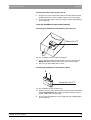
6.5.2 Preparing for scanning of the crown stump
6.5.2.1 Important information
Please be sure to observe the following:
Alignment of the crown stump
Fig. 6-6 Crown stump in the model holder
A
Center line of crown stump / C
center line (of model holder)
B
Model holder
Scanning angle
Careful alignment of the crown stump in the model holder is important for
successful scanning. The center line of the crown stump must coincide with
the center line of the model holder in all directions.
Length of the crown stump
The length of the crown stump including the model holder must not exceed 40
mm.
Form of the crown stump
The plastic material should taper off evenly moving toward the model holder.
No plastic material may stick to the sides of the crown stump, especially near
the active scanning area.
CAUTION: Leaving the preparation margin visible
The scanning process is performed on the axially rotating model holder. The
preparation margin therefore must remain visible from all sides (removal of
the marginal gingival junction).
9 The preparation margin is not visible from all sides.
¾
36
Prepare the duplicate or the saw-cut model of the crown stump.
59 07 568 D 3329
D 3329.201.02.17.02 05.2009
6 Operation
Sirona Dental Systems GmbH
Preparing optical scanning
Operating Instructions inLab
CAUTION: Faulty scanning result
An occlusal concave preparation cannot be properly scanned by the laser
using a "crown framework" model holder.
¾
Create a duplicate for an occlusal concave preparation. Use the "bridge
framework" model holder for the scanning process.
NOTE:
An incorrect alignment will result in a ceramic block suggestion that is larger
than the normal block size.
Bring the center line of the crown stump into alignment with the center line (of
the model holder).
6.5.2.2 Preparing for scanning
Preparing for scanning of the crown stump
59 07 568 D 3329
D 3329.201.02.17.02
05.2009
9
The preparation margin is not visible from all sides.
1.
Fasten the crown stump in the model holder using a plastic material.
2.
Treat the crown stump with a contrast agent if necessary.
3.
Lower the plastic material for improved visualization.
ª
The material is scanned at a 90° angle to the block axle.
ª
When the process has been completed, the view is rotated by the
software so that you obtain an occlusal view.
37
6 Operation
Sirona Dental Systems GmbH
Preparing optical scanning
Operating Instructions inLab
6.5.3 Preparing the Scanning of the Bridge
Abutments
CAUTION: Leaving the preparation margin visible
The preparation margin therefore must remain visible from all sides (removal
of the marginal gingival junction).
9 The preparation margin is not visible from all sides.
¾
Prepare the duplicate with the prepared bridge abutments.
A
B
Fig. 6-7 Position of the model
Fastening the model
A
Allen screw
B
Center line
9
The preparation margin is not visible from all sides.
¾
Fasten the model in the correct position with the Allen screw.
Valid scan range of the model:
z
The lowest area must not lie more than 2 mm below the center line of the
model holder.
z
The highest area must not lie more than 15 mm above the center line of
the model holder.
Fig. 6-8 Inexact setup (too low)
NOTE: Hollow spaces in the images
If the model is mounted too low, this may cause hollow spaces to appear in
the scanned images.
38
59 07 568 D 3329
D 3329.201.02.17.02 05.2009
6 Operation
Sirona Dental Systems GmbH
Preparing optical scanning
Operating Instructions inLab
Fig. 6-9 Maximum dimensions
C
Setup area
The cervical margins of both abutments must be aligned parallel to the center
line.
The front (anterior) abutment must be as close as possible to the clamping
shank. The maximum length of the model is 40 mm, and its maximum width
is 14 mm.
NOTE: "Orientation of bridges on model holder"
See Operator's Manual, chapter on "Design technique: Framework".
59 07 568 D 3329
D 3329.201.02.17.02
05.2009
39
6 Operation
Sirona Dental Systems GmbH
Preparing optical scanning
Operating Instructions inLab
6.5.4 Preparing for scanning of the WaxUp model
6.5.4.1 Preparations and creating the wax model
NOTE:
Observe the information and work steps in the document "Working
instructions for WaxUp“, Order No.: 60 01 361.
6.5.4.2 Valid scan range of the WaxUp model:
The following drawing illustrates the proportions which play an especially
important role when scanning the WaxUp model.
16mm
14mm
Fig. 6-10 Dimensions of the WaxUp holder
The diameter of the WaxUp holder is 16mm. The crown/bridge caps should
not be lower than 14mm.
NOTE:
The WaxUp model should be located as deep as possible on the WaxUp
holder. The cervical margin of the WaxUp model should be flush with the
bottom edge of the WaxUp holder.
6.5.5 Preparing for scanning of the veneer model
9
You have made a model of the clinical situation in the usual manner.
¾
Glue this model onto the model holder. The prepared labial surface must
point toward the slot on the model holder.
ª
The holder is automatically turned so that the scanning process can be
performed from the labial direction.
Fig. 6-11 Veneer model
A
40
Slot on model holder
59 07 568 D 3329
D 3329.201.02.17.02 05.2009
7 Maintenance
Sirona Dental Systems GmbH
Changing the water
Operating Instructions inLab
7
Maintenance, 1st note
Maintenance
NOTE: Observe national regulations!
Some countries have legal regulations which require regular safety
inspections of electrical devices or systems by the operator.
Maintenance, 2nd note
NOTE: Perform maintenance regularly!
Have maintenance performed on your unit annually by trained technical
personnel / a service engineer.
Maintenance, 3rd note
NOTE: Observe error messages
You must observe error messages shown on the display on in the software. If
the error message does not disappear even after you have performed the
prompted action, contact your service engineer.
DENTACLEAN
NOTE: Clean water paths regularly
Clean the water paths annually using the DENTACLEAN cleaning set.
7.1
Changing the water
7.1.1 General information
CAUTION: Damage to the pump and milling drives!
An excessively high ceramic content in the cooling water will damage the
pump and milling drives.
Change the water regularly!
When it is time for the water to be changed, a message window appears on
your monitor to remind you that it is time to change the water.
Preventing odors
NOTE: Odors!
All milling additives contain a biologically degradable preservative. Despite
this, however, odors may still develop under unfavorable conditions.
Observe the following:
59 07 568 D 3329
D 3329.201.02.17.02
05.2009
z
Change the water at least once a week.
z
With ambient temperatures above 25°C, change the water every 2 to 3
days to prevent foul odors.
z
Drain the tank if you do not intend to operate the unit for more than one
week.
z
Clean the tank if the odors recur.
z
Add DENTATEC milling additive and fill the tank up to the brim with water.
Let it stand for at least 24 hours and then rinse it out thoroughly with water
once again.
41
7 Maintenance
Sirona Dental Systems GmbH
Changing the water
Operating Instructions inLab
CAUTION: Damage to surfaces!
DENTATEC milling additive etches plastic surfaces in undiluted form and can
cause discoloration.
¾
Do not place DENTATEC on the unit.
¾
Do not spill DENTATEC.
CAUTION: Permissible milling additive
Use only DENTATEC as a milling additive.
7.1.2 Changing the water
Water tank, inLab/CEREC 3
Fig. 7-1 2 liter water tank
A
Tank catch
B
Water tank
When changing the water, proceed as follows:
42
9
The unit is switched on.
9
No milling/scanning process is running.
1.
Open the flap on the front panel of the unit.
To open the front flap, pull it on both sides.
2.
Press the tank catch upward and carefully pull out the water tank toward
the front of the unit.
3.
Drain the water out of the water tank through the drain opening.
59 07 568 D 3329
D 3329.201.02.17.02 05.2009
7 Maintenance
Sirona Dental Systems GmbH
Changing the water
Operating Instructions inLab
4.
Open the water tank and rinse it out.
5.
Check the water tank and the filter for dirt and contamination.
6.
If the water tank or the filter is dirty, clean it thoroughly under running
water. Detach the filter, rinse it out with water, and then reinsert it.
CAUTION: Inadmissible foam!
If any cleaning agents are used, this will result in an inadmissible foam.
Do not use any cleaning agents.
7.
Add approx. 50 ml* of DENTATEC to the tank.
or
¾ * With the materials IVOCLAR VIVADENT IPS Empress CAD and
IVOCLAR VIVADENT IPS e.max CAD, approx. 75 ml.
NOTE: Recommended mixing ratio:
25ml of DENTATEC with 1l of water.
Deviations are possible for certain materials:
¾
With IVOCLAR VIVADENT IPS Empress CAD and IVOCLAR
VIVADENT IPS e.max CAD, mix approx. 37.5ml with 1l of water.
¾
With CAD-Waxx, mix approx. 5ml with 1l of water. See also the operating
instructions for the corresponding material.
8.
Fill the tank up to the notch with water (bottom edge of cover; approx. 2
liters).
9.
Close the water tank.
10. Push the water tank back into the housing just far enough so that the tank
catch engages (press the catch downward if necessary).
59 07 568 D 3329
D 3329.201.02.17.02
05.2009
43
7 Maintenance
Sirona Dental Systems GmbH
Milling instruments
Operating Instructions inLab
7.2
Milling instruments
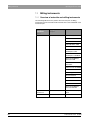
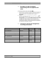
7.2.1 Overview of materials and milling instruments
The following table shows the position where the two pairs of milling
instruments must be inserted and the materials that can be milled with each
instrument pair:
Milling
instrument
Milling instrument
Material
"Right"
"Left"
Step Bur 12
Cylinder Pointed Bur
CEREC Blocs
CEREC Blocs PC
VITA MARK II
VITA ESTHETIC LINE
VITA TriLuxe
IVOCLAR VIVADENT
IPS Empress CAD
IVOCLAR VIVADENT
IPS Empress CAD Multi
IVOCLAR VIVADENT
IPS e.max CAD
VITA In-Ceram
ZIRCONIA
VITA In-Ceram ALUMINA
VITA In-Ceram SPINELL
Merz Artegral
Sirona inCoris ZI
Sirona inCoris AL
VITA In-Ceram YZ
VITA In-Ceram AL
IVOCLAR VIVADENT
IPS e.max ZirCAD
44
Step Bur 14 /
Cone Bur 14
Cylinder Pointed Bur
asymmetric blocks, Flip
Block
Cone Bur 12
Cylinder Pointed Bur
CAD-Waxx
59 07 568 D 3329
D 3329.201.02.17.02 05.2009
7 Maintenance
Sirona Dental Systems GmbH
Milling instruments
Operating Instructions inLab
7.2.2 Changing milling instruments (burs)
Unscrewing the milling instruments
Unscrewing the milling instruments
NOTE: Regular replacement of the Milling instruments
Change the milling instruments as soon as the system prompts you to do
this.
Change the milling instruments after using them to mill 20 restorations at the
latest.
After 30,000 minutes of milling operation, a maintenance prompt is displayed
during each milling instrument change until the service technician performs
maintenance and the milling time is reset.
9
The torque wrench is ready-to-hand.
1.
Select the command "Settings"/ "Instruments" in the menu line.
2.
If several milling units are connected, a dialog box will appear. Select the
language you prefer and confirm your choice with "OK".
ª The motors travel to the change position for the milling instruments.
The "Change instruments" dialog box opens.
3.
Press the catch of the milling chamber door and open the door.
WARNING: Risk of injury on milling instruments
If you put your hand in the milling chamber, you could injure it on the milling
instruments.
Be careful not to brush against the milling instruments with your hand.
4.
Loosen the worn out/defective milling instrument with the torque key and
unscrew it counterclockwise by hand.
Suitable milling instruments for inLab
CAUTION: Use only suitable milling instruments!
Do not use CEREC 2 milling instruments with chuck (1.2 mm) or 2.0 mm
milling instruments in this milling unit.
The Step Bur 14 and Cone Bur 14 milling instruments are used in connection
with the inLab gearing (serial number 11 200 and higher) to process the
following asymmetric blocks:
– VITA In-Ceram 2000 YZ CUBES: YZ-55 (Flip Block), YZ-20/19, YZ-40/19
– VITA In-Ceram 2000 AL CUBES: AL-20, AL-40
Any use of other materials may result in failures when creating the restoration
and cause damage to the unit.
Inserting the new milling instrument
1.
Screw the new milling instrument into the gearing by turning it clockwise
by hand; then tighten it securely with the torque key until you hear an
audible clicking noise.
NOTE: Faulty milling results
Interchanging milling instruments leads to faulty milling results.
2.
59 07 568 D 3329
D 3329.201.02.17.02
05.2009
Close the milling chamber door.
45
7 Maintenance
Sirona Dental Systems GmbH
Milling instruments
Operating Instructions inLab
Fig. 7-2 Changing milling instruments (burs)
3.
Select the milling instrument(s) you have inserted on the PC and click
"Start" (also refer to Operator's Manual).
CAUTION: Cleaning cooling water nozzles
The cooling water nozzles in the milling chamber always must be kept free of
lime and milling dust deposits. The corresponding cooling water jet always
must strike the milling instrument accurately!
9 The cooling water nozzles are dirty.
¾
Clean the nozzles with a cleaning wire and the SPRAYVIT syringe (if
available).
Changing defective milling instruments (burs)
Changing a defective milling
instrument
46
If a milling instrument breaks during a milling operation, the corresponding
motor travels to the change position. A dialog box which marks the side with
the broken milling instrument with a red cross then opens.
9
The milling instrument is broken.
1.
Change the defective milling instrument as described above.
2.
Select the milling instrument which you have inserted.
3.
Press the "Start" button.
59 07 568 D 3329
D 3329.201.02.17.02 05.2009
7 Maintenance
Sirona Dental Systems GmbH
Care and cleaning agents
Operating Instructions inLab
7.3
Care and cleaning agents
CAUTION: Approved care and cleaning agents
Use only care and cleaning agents which have been approved by Sirona!
A list of care and cleaning agents is provided in the Appendix.
A continuously updated list of approved agents can be downloaded from the
internet at:
"www.sirona.com" / "SERVICE" / "Downloads" / "Care and
cleaning agents"
If you do not have any access to the internet, you can order the list in one of
the following two ways:
z
Order from your local dental depot
z
Order from Sirona:
Tel: ++49 (0) 62 51 / 16-16 16
Fax: ++49 (0) 62 51 / 16-18 18
Order No.: 59 70 905
7.4
Cleaning surfaces
CAUTION: Care and cleaning agents
Use only cleaning and care agents which have been approved by Sirona, see
Cleaning and care agents [ 47].
CAUTION:
Do not allow liquids to run into the ventilation slots!
7.4.1 Disinfecting
Wiping off surfaces with surface disinfectants (wipe disinfection).
Observe the manufacturer’s instructions regarding restrictions for use.
7.4.2 Protection against medicaments
Due to their high concentrations and the substances they contain, many
medicaments can dissolve, etch, bleach or discolor surfaces.
CAUTION: Damage to the surface
Clean the surface immediately with a moist cloth and a cleaning agent.
7.4.3 Cleaning
Remove dirt, grime and disinfectant residue regularly using mild,
commercially available cleaning agents.
59 07 568 D 3329
D 3329.201.02.17.02
05.2009
47
7 Maintenance
Sirona Dental Systems GmbH
Replacing the main fuses
Operating Instructions inLab
7.5
Replacing the main fuses
Warning: main fuse
WARNING: Electric shock
Disconnect the power plug at the unit end before replacing the fuses.
CAUTION: Fuse type
Use only fuses of the same type in the fuse holder!
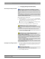
Fig. 7-3 Main fuses
A
Cover
C
Fuse holder
B
CC
D
Fuse
Replacing fuses
Fuses:
48
T5H250V
Order No. 20 33 111
9
The power plug must be disconnected.
1.
Use a screwdriver to carefully pry off the cover of the fuses on the back
side of the unit.
2.
Pull out the fuse holder.
3.
Replace the defective fuses.
4.
Reinsert the fuse holder.
5.
Close the cover.
59 07 568 D 3329
D 3329.201.02.17.02 05.2009
7 Maintenance
Sirona Dental Systems GmbH
Removing water from the unit
Operating Instructions inLab
7.6
Removing water from the unit
You must remove the water from the unit if you will not be using it for a longer
period of time or wish to transport it.
59 07 568 D 3329
D 3329.201.02.17.02
05.2009
9
No milling/scanning process is running.
1.
Open the flap on the front panel of the unit.
To open the front flap, pull it on both sides.
2.
Press the tank catch upward and carefully pull out the water tank toward
the front of the unit.
3.
Open the water tank, drain it and reinsert it.
4.
You can start the service program after installing the inLab 3D program
in the "inLab" program group. To do this, click "Start" / "Programs"
/ "inLab" / "Service".
5.
You can also change the water of the milling unit without a service
password by clicking the "Maintenance only"button.
6.
Let the water pump continue running until no more water comes out of the
nozzles (approx. 1min.).
7.
Pull out the water tank and empty it.
8.
Push the water tank back into the housing just far enough so that the tank
catch engages (press the catch downward if necessary).
49
8 Technical description
Sirona Dental Systems GmbH
System requirements
Operating Instructions inLab
8
Technical description
8.1
System requirements
Working without the acquisition unit
An inLab system PC is required to run this software. The hardware version
must be PC Hardware A or higher.
Working with the acquisition unit
If you work with the acquisition unit, it must have the hardware status PC
Hardware EA or higher.
8.2
Milling unit
Technical description of inLab_CEREC3
Digital feed control with force monitoring for extremely sensitive
processing of ceramic materials
Process-controlled milling motors
Positioning step size:
12,5 μm
Milling repeatability:
+/- 30 μm
Milling speed:
approx. 0.4-0.6 mm/min
Technical description of inLab burrs
Milling instruments (performance-monitored, backlash-free bearing)
Grain size:
64 μm
Speed:
40.000 rpm
Step Bur 12
included in the scope of
supply
Cylinder Pointed Bur
included in the scope of
supply
Step Bur 14
included in the scope of
supply
Cylinder Bur 1.2 mm
optionally available
Cylinder Bur 1.6 mm
optionally available
Cone Bur 10
optionally available
Cone Bur 12
optionally available
Cone Bur 14
optionally available
Step Bur 10
optionally available
NOTE:
You will find an overview of the old and new designations for the milling
instruments in the table in the appendix.
50
59 07 568 D 3329
D 3329.201.02.17.02 05.2009
8 Technical description
Sirona Dental Systems GmbH
Milling unit
Operating Instructions inLab
8.2.1 Technical data
Type designation
Milling unit inLab
Rated line voltage
100V - 230V AC
Rated power frequency
50/60 Hz
Rated current
1.5 - 3.5 A
Nominal power output:
320 VA
Permissible line voltage fluctuations
±10% of nominal voltage
Type of protection against electric shock
Unit classified as a Class 1
device
Degree of protection against ingress of
water
Ordinary device (without
protection against ingress of
water)
Overvoltage category
II
Ambient conditions
For indoor use
Pollution degree 2
Air pressure: 700 hPa –
1060 hPa
59 07 568 D 3329
D 3329.201.02.17.02
05.2009
Temperature range
5°C to 40°C
Humidity range
80% rel. up to 31°C
decreasing to
50% rel. up to 40°C
Mode of operation
Continuous operation
Dimensions (WxHxD) in mm
480 x 250 x 440
Approx. weight
30 kg
51
8 Technical description
Sirona Dental Systems GmbH
Milling unit
Operating Instructions inLab
8.2.2 Scanner for optical measurement of the
preparation
Technical data of scanner
z
Noncontact optical measurement
z
Digital control of the axes for fast measurement
z
Measuring speed: approx. 2 mm/min
z
Measuring technique: active triangulation
z
Active suppression of reflections
z
Low noise photodiode array
z
Laser light source:
z
Wavelength
670 nm
Focus diameter
≤25 μm
Scan range:
Scanning technique:
45° model
40x20x16
(LxWxH in mm)
15° model
40x20x12
(LxWxH in mm)
Crown
framework
16x25
(dia. x L in mm)
8.2.3 Controller board:
52
z
Real Time Micro Controller Board C167
z
6-axis stepping motor controller
z
2 DC motor controllers with integrated speed and current control
z
RS-232 interface 115kBaud
59 07 568 D 3329
D 3329.201.02.17.02 05.2009
8 Technical description
Sirona Dental Systems GmbH
Radio module (optional)
Operating Instructions inLab
8.3
Radio module (optional)
European/US radio interface (Höft & Wessel)
Transmission speed:
115.2 kBaud
Range:
up to 60m indoors,
up to 300m outdoors
Data interface;
RS-232
Operating temperature
0°C to +55°C
Radio interface, DECT/T-Sinus 45 Data 1 (Telekom)
59 07 568 D 3329
D 3329.201.02.17.02
05.2009
Transmission speed:
115.2 kBaud
Range:
up to 50m indoors,
up to 300m outdoors
Data interface;
RS-232
Operating temperature
+5°C to +45°C
53
9 Appendix
Sirona Dental Systems GmbH
Procedure in case of problems downloading via the DECT radio interface
Operating Instructions inLab
9
Appendix
9.1
Procedure in case of problems
downloading via the DECT radio
interface
See “Download via the DECT radio interface [ 22]“
Problems with DECT and H&W
1.
Make sure that the radio interface(s) is (are) correctly connected.
2.
Shut down the PC and switch it off. Unplug the plug-in power supply of
the PC radio interface from the power outlet for 5 seconds. Switch the
milling unit off. Restore all cable connections and test these. Start over
again at Preparations, Item 2.
3.
Open the "Settings" / "Configuration" / "Devices..." menu.
Select the required milling unit in the "Configure Devices" dialog
box and click the "Configure" button. Make sure that the correct COM
interface and baud rate have been selected. The baud rate must be set
to 115200. If an optical impression unit is used, set the COM 1 port. When
using a PC set the port to which the radio interface is connected.
4.
Should the installation of the software on the milling unit fail again,
attempt the installation using the serial cable supplied.
9.2
Procedure in case of problems
downloading via the Höft&Wessel radio
interface
See “Download via the Höft&Wessel radio interface [ 23]“
Problems with DECT and H&W
54
1.
Make sure that the radio interface(s) is (are) correctly connected.
2.
Shut down the PC and switch it off. Unplug the plug-in power supply of
the PC radio interface from the power outlet for 5 seconds. Switch the
milling unit off. Restore all cable connections and test these. Start over
again at Preparations, Item 2.
3.
Open the "Settings" / "Configuration" / "Devices..." menu.
Select the required milling unit in the "Configure Devices" dialog
box and click the "Configure" button. Make sure that the correct COM
interface and baud rate have been selected. The baud rate must be set
to 115200. If an optical impression unit is used, set the COM 1 port. When
using a PC set the port to which the radio interface is connected.
4.
Should the installation of the software on the milling unit fail again,
attempt the installation using the serial cable supplied.
59 07 568 D 3329
D 3329.201.02.17.02 05.2009
9 Appendix
Sirona Dental Systems GmbH
Procedure in case of problems downloading with the supplied serial cable
Operating Instructions inLab
9.3
Procedure in case of problems
downloading with the supplied serial
cable
See “Download using the serial cable supplied [ 20]“
1.
Shut down the PC and switch it off. Switch the milling unit off. Restore all
cable connections and test these. Make sure that you have used the 2
meter long serial interface cable supplied. Start over again at
Preparations.
2.
Open the "Settings" / "Configuration" / "Devices..." menu.
Select the required milling unit in the "Configure Devices" dialog
box and click the "Configure" button. Make sure that the correct COM
interface and baud rate have been selected. The baud rate must be set
to 115200. When using an acquisition unit with external interface
extension set the COM 2 port. When using an acquisition unit without
external interface extension, you must proceed as for a PC and select the
port to which the serial cable is connected.
9.4
Overview of old and new designations
for milling instruments
Old designation on packaging
New designation on
packaging
Order No.
Quantity per
package
Step - burr Diamond XL
Step Bur 12
60 52 265
6
Cone - shaped Cylinder Diamond dia. 1.6 mm
Cylinder Pointed Bur
58 55 734
6
Cylinder Diamond dia. 1.2mm – long
Cylinder Bur dia. 1.2
54 66 151
10
Cylinder Diamond dia. 1,6mm – long
Cylinder Bur dia. 1.6
54 66 193
6
Cone - shaped Diamond
Cone Bur 10
58 85 103
6
Cone - shaped Diamond XL
Cone Bur 12
59 35 668
6
Cone - Diamond "Flip - Block" 14 mm
Cone Bur 14
59 99 771
6
-
Step Bur 10
60 89 010
6
-
Step Bur 14
60 89 028
6
59 07 568 D 3329
D 3329.201.02.17.02
05.2009
55
Sirona Dental Systems GmbH
Index
Operating Instructions inLab
Index
B
Block changing tool
26
Building installation 10
C
Calibration phantom
27
Calibration pin
27
Calibration tools
Calibration phantom 25
Calibration pins 25
Storage 27, 30
Care and cleaning agents 47
CC 15
CE mark 9
change
Milling instruments 45
Cooling water nozzles 46
D
Dimensions 51
Disinfection 47
F
Footprint 13
Fuse
Fuse type 48
Order Number 48
replacement 48
H
Humidity range 51
I
Installation site 13
Intended use 9
56
59 07 568 D 3329
D 3329.201.02.17.02 05.2009
Sirona Dental Systems GmbH
Index
Operating Instructions inLab
L
Laser class
Class 1 11
Class 2 11
M
Maintenance 10
Regulations 41
Measuring technique 52
Milling instruments 28, 45, 50
Changing a defective instrument 46
Milling speed 50
Milling unit
Overview 14
Mode of operation 51
P
Packaging 13
Packing 24
Ports 15
Power connection 15
Product safety 10
Protection class 51
R
Rated current 51
Rated line voltage 51
Repair 10
S
Scan range 52
Scanning technique 52
15° model 52
45° model 52
Crown framework 52
Scope of supply 24
Setscrew
27
T
Tank catch 16, 42
Temperature range 51
59 07 568 D 3329
D 3329.201.02.17.02
05.2009
57
Sirona Dental Systems GmbH
Index
Operating Instructions inLab
Torque wrench
26, 27
Transport 13
Type designation 51
U
Unpacking 13
W
Warranty 8
water 51
Water tank
Changing the water 42
Filling 16
Odors 41
Removing water from the unit 49
Water change 41
Weight 51
58
59 07 568 D 3329
D 3329.201.02.17.02 05.2009
Sirona Dental Systems GmbH
Operating Instructions inLab
59 07 568 D 3329
D 3329.201.02.17.02
05.2009
Index
59
tÉ=êÉëÉêîÉ=íÜÉ=êáÖÜí=íç=ã~âÉ=~åó=~äíÉê~íáçåë=ïÜáÅÜ=ã~ó=ÄÉ=êÉèìáêÉÇ=ÇìÉ=íç=íÉÅÜåáÅ~ä=áãéêçîÉãÉåíëK
«=páêçå~=aÉåí~ä=póëíÉãë=dãÄe=OMMV
a=PPOVKOMNKMOKNTKMO MRKOMMV
péê~ÅÜÉW=ÉåÖäáëÅÜ=
ûKJkêKW= NNN=PVN
mêáåíÉÇ=áå=dÉêã~åó
fãéêáã¨=Éå=^ääÉã~ÖåÉ
páêçå~=aÉåí~ä=póëíÉãë=dãÄe
áå=íÜÉ=rp^W
c~Äêáâëíê~≈É=PN
SQSOR=_ÉåëÜÉáã
dÉêã~åó
ïïïKëáêçå~KÅçã
páêçå~=aÉåí~ä=póëíÉãë=ii`
QUPR=páêçå~=aêáîÉI=pìáíÉ=NMM
`Ü~êäçííÉI=k`=OUOTP
rp^
lêÇÉê=kç
RV=MT=RSU=a=PPOV